Centrosolar Solara Cell-Protector User manual

CENTROSOLAR AG Stresemannstraße 163 22769 Hamburg GERMANY Tel.: +49 (0)40 3910650 hamburg@centrosolar.com
Mit dieser Anschlussart werden die Zellen durch zwei
Bypass-Dioden vor dem Hotspot Effekt geschützt. Eine
Sperrdiode schützt zusätzlich vor Rückstrom ins Modul.
Werden mehrere Module parallel betrieben, kann so bei
Beschädigung von einem Modul oder Kabel ein Einfluss
auf weitere Module verhindert werden.
Installation Zellprotektor
Betrifft nur SOLARA Solarmodule mit dreiadrigem Anschlusskabel!
Wichtige Hinweise!
Bevor Sie Ihr Solarmodul in Betrieb nehmen dürfen, muss zunächst der mitgelieferte Zellprotektor ange-
schlossen werden!
■Jedes einzelne Modul mit einem 3-adrigen Kabel muss
am Kabelende mit dem Zellprotektor verbunden werden!
Polaritäten:
rot = Solarmodul „+“
blau = Solarmodul „-“
grün = Mittelkontakt
■Erst nach dem Anschluss des Zellprotektors dürfen die
Module in Reihe oder Serie verschaltet werden.
■Der Zellprotektor muss in einem trockenen Bereich
installiert werden und darf nie nass oder feucht werden!
Anschluss Zellprotektor
1. Schrauben Sie die drei Adern vom Modulkabel in die Klemmenleiste „Solar“. Farbkodierung beachten!
Auf sicheren Sitz der Adernhülsen in den Schraubklemmen achten.
2. An Klemmleiste „Output“ mit einem Standardkabel (2 x 1,5 mm ) die Verbindung zum Laderegler herstellen.
Zwei Anschlussarten sind möglich, siehe unten. Unbedingt die Polarität +/- beachten.
3. Mit den beiliegenden zwei Kabelklemmen fixieren Sie die Kabel am Gehäuse.
4. Deckel auf die Grundplatte schrauben – fertig.
Zellprotektor mit Platine
Zellprotektor fertig montiert
Anschlussarten A und B
A Bypass-Dioden (Standardmethode)
links: zwei Kabel zum Laderegler, Klemmen „+“, „-“
Mit dieser Anschlussart werden die Zellen durch zwei
Bypass-Dioden vor dem Hotspot Effekt geschützt.
B Bypass-Dioden + Rückstromschutz
links: zwei Kabel zum Laderegler, Klemmen „+_D“, „-“
Polarität bzw. Farbkodierung
für die Anschlussleitungen
zum Laderegler Modulkabel
Schraubklemmen
„Output“
3-fach Schraubklemmen
„Solar“

CENTROSOLAR AG Stresemannstraße 163 22769 Hamburg GERMANY Tel.: +49 (0)40 3910650 hamburg@centrosolar.com
+
-
+
-+
-+
-
Solar
+
+_D
-
red
green
blue
Output
= 6A, 60V
- -
+
-+++
-
+
- - +
-+
Funktion Zellprotektor
Der Zellprotektor hat die Aufgabe die Zellen im Modul bei teilweiser Abschattung des Solarmoduls vor Überhitzung (Hotspot)
zu schützen. Hierzu sind auf der Platine zwei Bypass-Dioden aufgelötet. Bei handelsüblichen Glasmodulen mit Alurahmen
befinden sich diese Bypass-Dioden in der Anschlussdose.
Bypass-Dioden können durch Überspannungen und Gewitter beschädigt werden. In der Anschlusskappe wäre ein Austausch
unmöglich. Deshalb sind bei Solara Marine Modulen die Bypass-Dioden im externen Zellprotektor eingebaut.
Zusätzlich ist auf der Platine eine Diode als Rückstromschutz eingebaut. Je nach Anschlussart kann diese Schutzfunktion ge-
nutzt werden. Allerdings entsteht durch die Schottky-Diode ein Spannungsverlust von ca. 0,6 V.
Anschlussgrafiken
Zellprotektor nur bei Modulen mit 3-adrigem Anschlusskabel erforderlich!
12 V: Paralleler Anschluss von 12 V Solarmodulen
Stromlaufplan Zellprotektor V2.2
24 V: Serieller Anschluss von 12 V Solarmodulen
12 V
12 V
12 V
12 V
12 V
12 V
12 V
12 V 12 V
Zell-
protektor
Zell-
protektor
Zell-
protektor
Zell-
protektor
Zell-
protektor
Zell-
protektor
Zell-
protektor
12 V Batterie-System 24 V Batterie-System

CENTROSOLAR AG Stresemannstraße 163 22769 Hamburg GERMANY Tel.: +49 (0)40 3910650 hamburg@centrosolar.com
With this hookup, the cells are protected with 2 bypass
diodes against the hot spot effect and the additional block-
ing diode protects against reverse current back into the
module. By damage to a module or cable by several mod-
ules in parallel operation, an influence can be prevented
on the other modules with the use of the blocking diode.
Installation Cell-Protector
Applies only to M-Series solar panels with three wire cable!
Attention!
Before using your solar panel, you have to connect the enclosed cell-protector!
■The cable of with each single M-Series solar panel with
a three wire cable has to be connected to a separate
cell-protector.
Polarities:
red = solar module “+”
blue = solar module “-”
green = middle contact
■The serial or parallel connection of M-Series solar panels
has to be done after installing the cell-protector(s).
■The cell-protector has to be mounted and operated in a
dry place, it must not become wet or moist with dew.
Connection of the cell-protector
1. Screw the 3 wires of the panel cable in the terminal block “Solar”. Please note the colour marking!
Each wire end have to be screwed down in the correct screw terminal.
2. Use for connection the charge controller a standard 2x1.5mm2 cable at terminal block “Output”.
Two kinds of connection are possible, please see below. Please pay attention to the polarity +/- .
3. Fix the cable to the base plate of the box by the 2 attached strain relief clamps.
4. Screw the cap of the box onto the base plate. The connection of the cell-protector is ready.
Cell-protector with PCB board
Cell-protector correctly installed
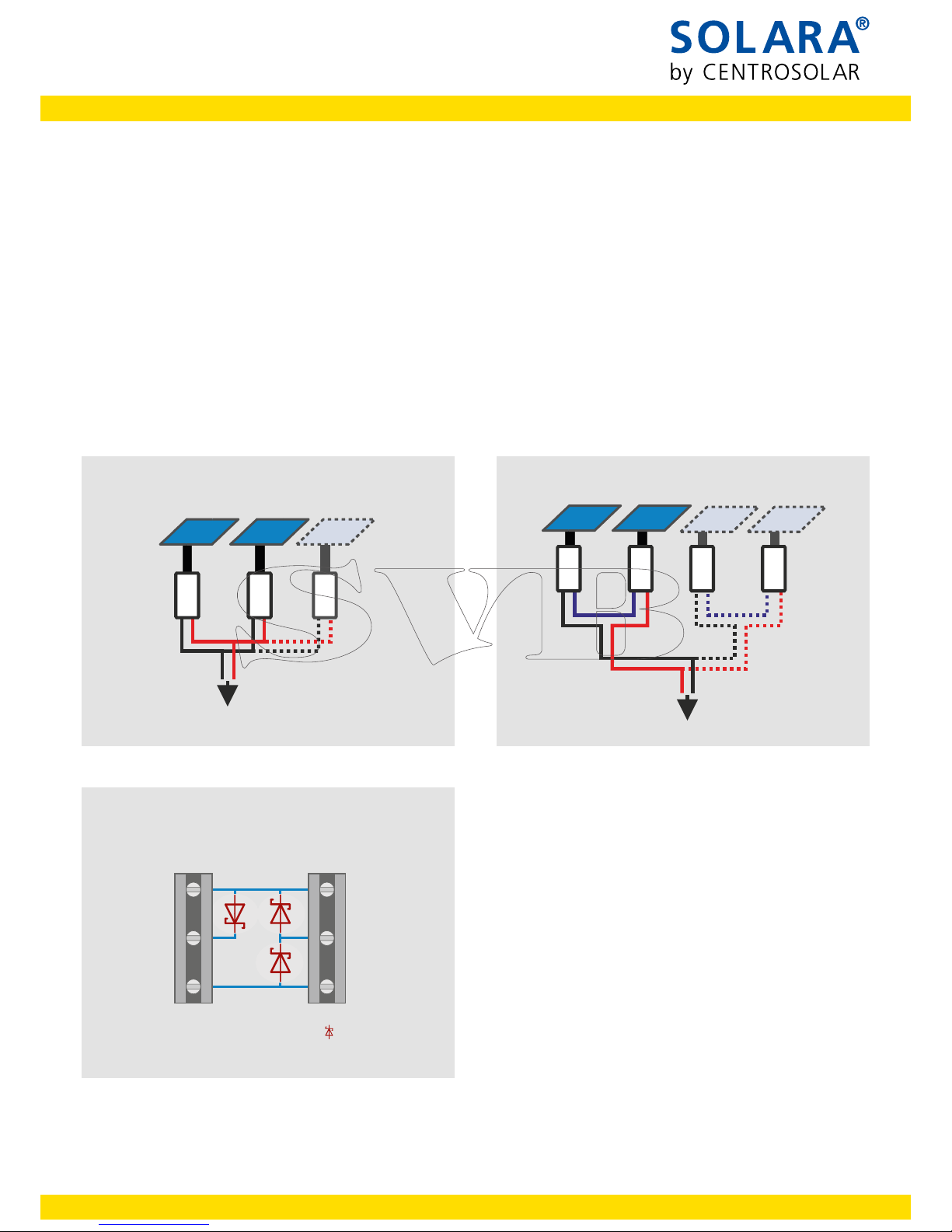
Type of connection A and B
A) Bypass diodes (standard method)
Left: two cables to charge controller, terminals “+”, “-”
With this hookup, the cells are protected with
2 bypass diodes against the hot spot effect.
B) Bypass diodes + Reverse current protection
Left: two cables to charge controller, terminals “+_D”, “-”
Polarity or color coding
for the connection cables
To charge controller Solar module cable
Screw terminals
“Output“
3-fold screw terminals
“Solar“

CENTROSOLAR AG Stresemannstraße 163 22769 Hamburg GERMANY Tel.: +49 (0)40 3910650 hamburg@centrosolar.com
+
-
+
-+
-+
-
Solar
+
+_D
-
red
green
blue
Output
= 6A, 60V
- -
+
-+++
-
+
- - +
-+
Function of the cell-protector:
The purpose of the cell protector is to prevent overheating of the solar cells (risk of hotspot) when the solar module is partial
shaded. This is achieved by the diodes on the circuit board. By standard aluminium framed glass modules these diodes are
located in the junction box on the backside of the modules.
The bypass diodes can be damaged by power surges and lightning. By fitting into the cap any replacement would be impos-
sible. Therefore the bypass diodes at the M-Series modules are installed in the external cell-protector. Additionally a diode is
incorporated on the PC-board to prevent reverse current. Depending on the kind of connection, this protection can be used.
However, the Schottky diode produces a voltage drop of about 0.6V.
Connection graphics
Cell protector required only for modules with 3-wire connection cable!
12V: Parallel connection of 12V solar modules
Circuit diagram cell-protector V2.2
24V: Serial connection of 12V solar modules
12 V
12 V
12 V
12 V
12 V
12 V
12 V
12 V 12 V
Cell-
protector
Cell-
protector
Cell-
protector
Cell-
protector
Cell-
protector
Cell-
protector
Cell-
protector
12 V battery system 24 V battery system
Table of contents
Languages:
Popular Protection Device manuals by other brands

Bticino
Bticino PLT1 instruction sheet

TAZ
TAZ SOVAR TECHNICAL NOTICE

Max-Air Systems
Max-Air Systems ME E 008-013 Series Installation, operation and maintenance instructions

ABB
ABB Relion 630 Series Applications manual

dehn
dehn DEHNcare APS Series User information

OUTSTEEL
OUTSTEEL BROUSSE S installation instructions