CenturyLink MP412 User manual

4-Line Music on Hold
and Paging Adapter
Model MP412
OWNER’S MANUAL
MP412 Manual_rev.qxd 6/15/05 12:23 PM Page 1

This equipment complies with Part 68 and Part 15 of FCC rules. On the base of this equipment is a label that contains, along with other information,
the FCC Registration Number and the Ringer Equivalence Number (REN) for this equipment. If requested, this information must be given to the
Telephone Company.
The REN is useful to determine the quantity of devices that you may connect to your telephone line and still have those entire devices ring when your
telephone number is called. In most but not all areas, the sum of the REN's of all devices connected to one line should not exceed five (5.0). To be
certain of the number of devices you may connect to your line, as determined by the REN, you should contact your local telephone company to
determine the maximum REN for your calling area.
If your equipment causes harm to the telephone network, the telephone company may discontinue your service temporarily. If possible, they will notify
you in advance. But if advance notice isn't practical, you will be notified as soon as possible. You will be informed of your right to file a complaint with
the FCC. Your telephone company may make changes in its facilities, equipment, operations or procedures that could affect the proper functioning of
your equipment. If they do, you will be informed in advance to give you an opportunity to maintain uninterrupted telephone service.
This equipment may not be used on a coin service line provided by the Telephone Company. Connection to party lines is subject to state tariffs.
1
FCC INFORMATION
1
MP412 Manual_rev.qxd 6/15/05 12:23 PM Page 2

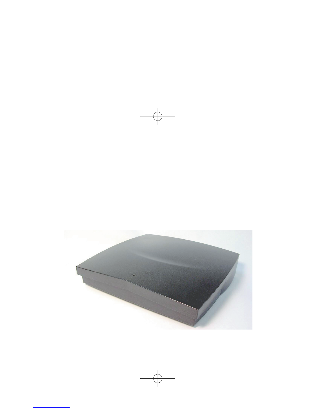
The MP412 System Features
CONGRATULATIONS! You have acquired a 4-line, fully featured music-on-hold and external paging unit designed to work with the
NSQ412 telephone system. Features include:
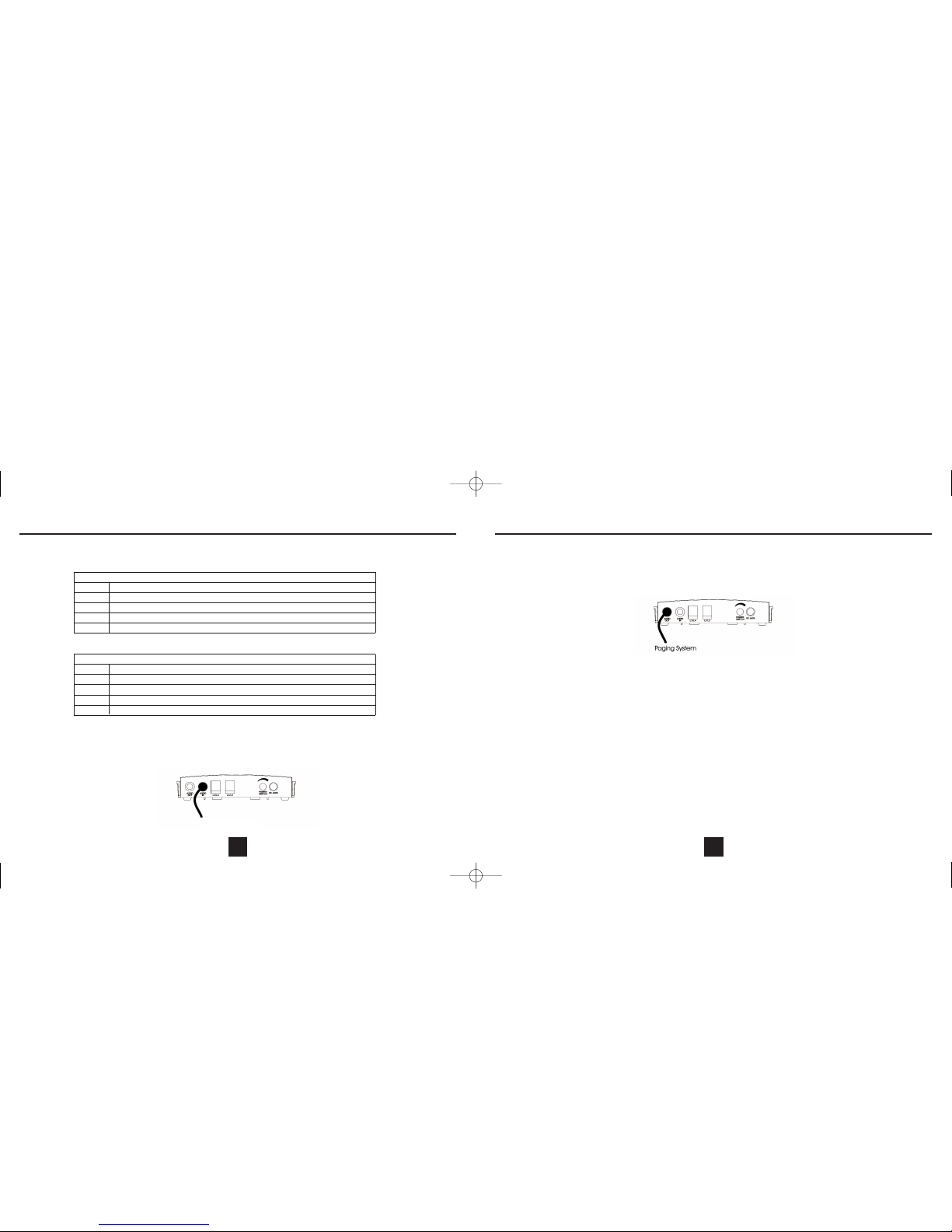
• Power and Paging LED
• Universal Music on Hold Input Jack
• AutoPlay Music on Hold (using built-in music IC)
• Universal Paging Output Jack
• Single Page Output
• All Page Output
• Paging Volume Adjustment
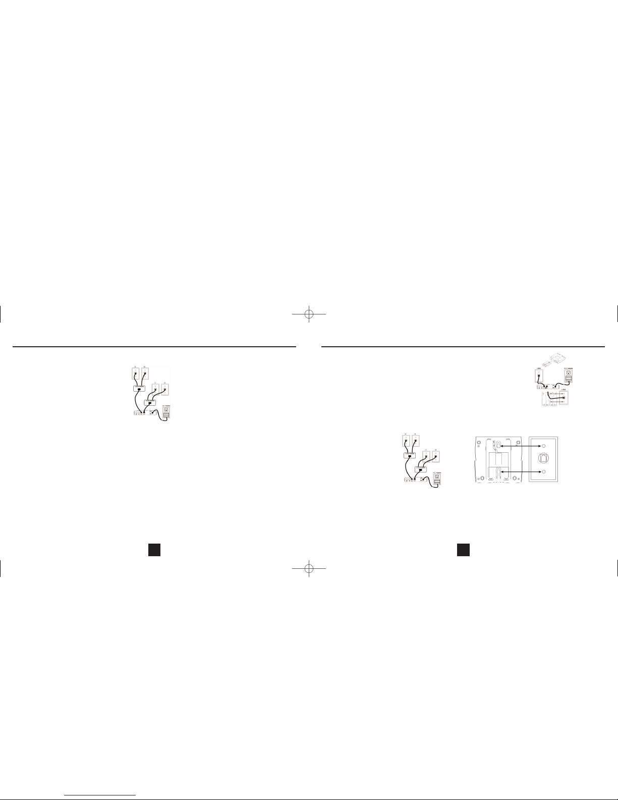
The Box Contents
Carefully remove the unit from its shipping carton. If there are any visible indications of damage to the unit or accessories, do not attempt to operate it.
Call International Resources at (888) 772-5200 for help.
Check the carton carefully for the following items. You should have:
Keep the box and all packing materials for storing or shipping the MP412. Keep all printed literature for reference. On the base unit bottom, there is a
serial number. Please write it below for future reference:
MOH 412 SERIAL NUMBER: ______________________________________
Some of the following information may not apply to your particular product; however, when using telephone equipment, basic safety
precautions should always be followed to reduce the risk of fire, electric shock and injury to persons, including the following:
1. Read and understand all instructions.
2. Follow all warnings and instructions marked on the product.
3. Unplug this product from the wall outlet before cleaning. Do not use liquid cleaners or aerosol cleaners. Use a damp cloth for cleaning.
4. Do not use this product near water, for example, near a bathtub, wash bowl, kitchen sink or laundry tub, in a wet basement or near a swimming
pool.
5. Slots and openings in the cabinet back or bottom are provided for ventilation, to protect it from overheating. These openings must not be blocked
or covered. The openings should never be blocked by placing the product on the bed, sofa, rug, or other similar surface. This product should not be
placed in a built-in installation unless proper ventilation is provided.
6. Use only the power cord and batteries indicated in this manual. Do not dispose of batteries in a fire. They may explode. Check with local codes for
possible special disposal instructions.
7. Do not allow anything to rest on the power cord. Do not locate this product where the cord will be abused by persons walking on it.
8. Do not overload wall outlets and extension cords as this can result in the risk of fire or electrical shock.
9. Never push objects of any kind into the product through cabinet slots as they may touch dangerous voltage points or short out parts that could
result in a risk of fire or electric shock. Never spill liquid of any kind on the product.
10. To reduce the risk of electrical shock, do not disassemble this product, but take it to a qualified serviceman when service or repair work is
required. Opening or removing covers may expose you to dangerous voltages or other risks. Incorrect reassembly can cause electric shock when
the appliance is subsequently used.
11. Do not expose the telephone to extreme temperatures such as found near a hot radiator or stove, or in a car parked in the summer sun.
12. Do not place lighted candles, cigarettes, cigars, etc., on the telephone.
13. Never touch uninsulated telephone wires or terminals unless the telephone line has been disconnected at the network interface.
14. Never install or modify telephone wiring during a lightning storm. Avoid using a telephone (other than a cordless type) during an electrical storm.
There may be a remote risk of electrical shock from lightning.
15. Never install telephone jacks in wet locations unless the jack is specifically designed for wet locations.
16. Use caution when installing or modifying telephone lines.
17. Do not use the phone to report a gas leak in the vicinity of the leak.
18. Unplug this product from the wall outlet and refer servicing to qualified service personnel under the following conditions.
A. When the power supply cord or plug is damaged or frayed.
B. If the product has been exposed to rain or water.
C. If the product does not operate normally by following the operating instructions.
D. If the product has been dropped or the cabinet has been damaged.
E. If the product exhibits a distinct change in performance.
SAVE THESE INSTRUCTIONS
31
INTRODUCTIONIMPORTANT SAFETY INSTRUCTIONS
2
MP412 Manual_rev.qxd 6/15/05 12:23 PM Page 4

Installation Preparation
Installing the MP412 is easy as long as you do a little planning before starting. Locate the unit within ten feet of an a. c. power outlet and seven feet of
the telephone jacks. The maximum amount of telephone wire that can be between the unit any station is 600 feet. The MP412 has been assigned the
station number 22. Any NSQ412 that uses this station number will have to be changed to another number.
IMPORTANT:Taking full advantage of the system features requires that the telephone number connected to Line 1 be the same on all stations. If this
is not done, the Page will not work properly. In addition, it is strongly recommended that no other devices operate on Line 1 or Line 2 besides the
NSQ412 stations and the MP412. Any interference on it can degrade the system performance. The system can be used on a DLS line if either: 1)
Line 1 is not the DSL line; or 2) Line 1 wiring connected to all stations is behind the DSL filter port.
CAUTION!
1. Never install telephone jacks during a lightning storm.
2. Never install telephone jacks in wet locations unless the jack is specifically designed for wet locations.
3. Never touch uninsulated telephone wires or terminals unless the telephone line has been disconnected at the network interface.
4. Use caution when installing or modifying telephone lines.
5. Always disconnect all telephone lines from the wall outlet before servicing or disassembling this equipment.
6. Danger of explosion if battery is incorrectly replaced.
Installing the Unit on a Desk or Table
NOTE: Do not connect the a. c. power adapter until instructed to do so.
The following instructions show how to connect four telephone lines to the MP412. As few as one line can be connected.
1. Carefully remove all of the unit components from their packing.
2. If telephone lines 1 and 2 are on one jack and telephone lines 3 and 4 are on another jack, see the following connection drawing. Otherwise, go to
step 3.
Connect telephone jack 1 to the MP412 L1/L2 jack using one of the 4-conductor telephone line cords supplied with the unit. Connect telephone
jack 2 to the MP412 L3/L4 jack using the other 4-conductor telephone line cord supplied with the unit.
5
GETTING STARTED
Key and Indicator Descriptions
The following drawings provide identification and brief descriptions of the control and indicator.
Power & Paging LED: Illuminates continuously for power, flashes to indicate paging or another NSQ412 has the same extension number.
Audio Out Jack: Used to provide the MP412 page signal to an external paging amplifier and speaker.
Audio In Jack: Used to connect an external music source for music on hold.
Line Jacks: Jack L1/L2 is used for telephone lines 1 and 2. Jack L3/L4 is used for telephone lines 3 and 4
Paging Volume Knob: Adjusts the paging level.
Power Jack: The jack for connecting the a. c. power adapter to the unit.
4
INTRODUCTION
MP412 Manual_rev.qxd 6/15/05 12:23 PM Page 6

6. Hold the station close to the telephone wall jack and plug the line cord into it. Align the wall
jack studs with the wall mounting holes on the MP412's back.
7. Push the MP412 onto the studs and firmly pull downward (toward the floor), locking the
station onto the wall jack.
8. Connect the other telephone jack with lines 3 and 4 to the MP412 jack L3/L4 using one long
4-conductor telephone line cord supplied with the unit.
9. Connect the a. c. adapter to an electrical outlet. The unit will initialize for about 7 seconds,
then be ready for use.
10. Follow these steps if the unit will be installed on screws securely fastened to the wall. If
telephone lines 1 and 2 are on one jack and telephone lines 3 and 4 on another jack see
the following connection drawing. Otherwise, go to step 11. Connect telephone jack 1 to the
MP412 L1/L2 jack using one of the 4-conductor telephone line cords supplied with the unit.
Connect telephone jack 2 to the MP412 L3/L4 jack using the other 4-conductor telephone line cord supplied with the unit.
11. If telephone lines 1, 2, 3 and 4 are all on separate jacks, two adapters and extra telephone line cords are necessary (not included with the
telephone). See the following connection drawing.
The adapters will convert two separate telephone jacks into a single one. Connect telephone line 1 into the adapter. Connect telephone line 2 into
the adapter. Connect the adapter output jack into the MP412 L1/L2 jack using one of the 4-conductor telephone line cords supplied with the unit.
Repeat this process using the second adapter for telephone lines 3 and 4. Connect the output of the second adapter jack to the MP412 L3/L4 jack
using the other telephone line cord supplied with the unit.
12. Using the supplied screw template, install the screws into the wall. Be sure to use anchors to ensure a secure mounting. Leave the screws
protruding from the wall 3/16”.
13. Hold the unit close to the screws and align them with the wall mounting holes on the mounting bracket's back. Push the unit onto the screws and
firmly pull downward (towards the floor), locking it to the wall.
14. Connect the a. c. adapter to an electrical outlet. The unit will initialize for about 7 seconds, then be ready for use.
7
GETTING STARTED
3. If telephone lines 1, 2, 3 and 4 are all on separate jacks, two adapters and extra telephone line cords are necessary (not included with the unit).
See the following connection drawing.
The adapters will convert two separate telephone jacks into a single one. Connect telephone line 1 into the adapter. Connect telephone line 2 into the
adapter. Connect the adapter output jack into the MP412 L1/L2 jack using one of the 4-conductor telephone line cords supplied with the unit. Repeat
this process using the second adapter for telephone lines 3 and 4. Connect the output of the second adapter jack to the MP412 L3/L4 jack using the
other telephone line cord supplied with the unit.
If your telephone wiring does not match either of the examples above or one of their variations, you may need to call your telephone service provider
for assistance. They can install the necessary jacks wired in the correct configuration.
4. Once the telephone line(s) are connected to the unit, plug the a. c. adapter into the MP412 power jack. The station will initialize for about 7
seconds, then be ready for use.
Installing the Unit on a Wall
The unit may be installed onto the studs of a telephone wall jack or onto 2 screws that are securely fastened to the wall. Once the telephone wall
jack-wiring configuration is determined, proceed with the installation. NOTE: Do not connect the a. c. adapter until instructed to do so.
The following instructions show how to connect four telephone lines to the MP412. As few as one line can be connected.
1. Carefully remove all of the components from their packing.
2. Insert the hooks of the wall mounting bracket into the matching slots located on the top half of the unit.
3. Connect the a. c. power adapter to the power jack on the MP412. Do not connect the adapter to the electrical outlet at this time.
If you are installing the MP412 to screws, skip down to step 10.
4. If you install the MP412 to the mounting studs of a telephone wall jack, lines 1 and 2 must be terminated to it. Lines 3 and 4 (if used) must be
terminated to a different jack.
5. Connect a 4-conductor telephone line cord supplied with the unit to the L1/L2 jack. Route the cord through the telephone line cord channel on the
mounting bracket's back.
6
GETTING STARTED
MP412 Manual_rev.qxd 6/15/05 12:23 PM Page 8

Voice Paging
The MP412 allows the NSQ412 system telephones to make a page over an external public address system.
Before using this feature, the MP412 must be connected to an external paging system (an audio amplifier connected to a speaker). Connect the
MP412 Audio Out jack to the low impedance input of the audio amplifier. Adjust the MP412 Paging Volume Knob to obtain the desired loudness from
the external paging speaker.
Note: The MP412 has been assigned the station number 22 automatically. It cannot be changed. If an NSQ412 telephone has this number, it must be
changed. The MP412 will let you know when a telephone has this number by the LED blinking slowly.
To page the external paging system from any NSQ412 telephone, press the [PAGE] and the [22] keys. After hearing the beep, begin speaking. When
done, press the NSQ412 [RELEASE] key or hang up.
To page all telephones and the external paging system from any NSQ412 telephone, press the [PAGE] and [*] keys. After hearing the beep, begin
speaking. When done, press the NSQ412 [RELEASE] key or hang up.
CARE AND MAINTENANCE
Place your unit in a location where its cords will be out of the way and where it is not likely to be knocked to the floor.
To clean, use a soft cloth, dampened in mild detergent. Never use abrasives or solvents and never spray cleaners directly onto the telephone.
RADIO FREQUENCY INTERFERENCE
WARNING! This equipment generates, uses and can radiate radio frequency energy and if not connected and operated in accordance with the
Owner's Manual, may cause interference to radio communications. It has been tested and found to comply with the limits for a Class A computing
device pursuant to Subpart J of Part 15 of the FCC Rules which are designed to provide reasonable protection against such interference when
operated in a commercial environment. Operation of this equipment in a residential area is likely to cause interference in which case the user at
his own expense will be required to take whatever measures may be required to correct the interference.
9
Basic Features
LED Illumination
The MP412 LEDs will indicate the station's status. The following chart identifies the different patterns that can occur during use.
The LED will indicate status according to the following chart:
Music on Hold
The system will play built-in music automatically for the caller when a line is placed on hold by an NSQ412. No set-up is required for this once the
MP412 is connected to the system. Note: The built-in music will periodically change to a different tune.
Other music or a message can be played instead of the built-in music. Connecting a radio, MP3 player or other device into the Audio In jack does this.
8
Basic Features
LED Illumination
LED State Specification
Dark Solid dark
Lit Solid lit
Slow flash 0.5S off, 0.5S on, repeatedly
Wink 1 0.250S off, 1.750S on, repeatedly
Unit LED Operation
Status Power/Page LED
Dark No Power
Lit Power
Wink 1 All Paged or Single Page
Slow One NSQ412 phone has the same ID (Ext. 22)
Audio Source
MP412 Manual_rev.qxd 6/15/05 12:23 PM Page 10

WALL MOUNT TEMPLATE
PROBLEMS YOU CAN SOLVE
NO OPERATION
Make sure the AC Power Adapter is plugged in to a live AC wall outlet and the MP412.
MP412 LED FLASHING SLOWLY
Check to see if an NSQ412 has a station ID of 22. If so, it must be changed.
EXTERNAL PAGING IS NOT HEARD
Turn up the MP412 Paging Volume.
10
Basic Features
PLACE THIS TEMPLATE ON THE WALL
THE LOCATION OF THE SCREWS IS INDICATED
BY THE CENTERS OF THE CROSSED LINES.
FASTEN THE SCREWS LEAVING 3/16” OF THE SCREW
EXTENDING FROM THE WALL.
REMOVE THIS PAGE
MP412 Manual_rev.qxd 6/15/05 12:23 PM Page 12

This unit is warranted to the original purchaser to be free from defects in materials and workmanship under normal installation, use and service for a
period of one (1) year from the date of purchase as shown on the purchaser's receipt.
The obligation of International Resources, Inc. under this warranty shall be limited to repair or replacement (at our option), during the warranty period,
of any part which proves defective in material or workmanship under normal installation, use and service, provided the product is returned to
International Resources, Inc. (address below) or to one of our authorized Service Centers, TRANSPORTATION CHARGES PREPAID. Products
returned to us or to an authorized Service Center must be accompanied by a copy of the purchase receipt. In the absence of such purchase receipt,
the warranty period shall be one (1) year from the date of manufacture.
This warranty shall be invalid if the product is damaged as a result of defacement, misuse, abuse, neglect, accident, destruction or alteration of the
serial number. Improper electrical voltages or currents, repair, alteration or maintenance by any person or party other than our own service facility or
an authorized Service Center, or any use violative of instructions furnished by us.
This warranty is also rendered invalid if this product is removed from the country in which it was purchased. If is used in a country in which it is not
registered for use, and/or if it is used in a country for which it was not designed. Due to variations in telephone systems and communications laws, this
product may be illegal for use in some countries. International Resources, Inc. assumes no responsibility for damages or penalties incurred resulting
from the use of this product in a manner or location other than that for which it is intended.
This one-year warranty is in lieu of all other expressed warranties, obligations, or liabilities, ANY IMPLIED WARRANTIES, OBLIGATIONS, OR
LIABILITIES, INCLUDING BUT NOT LIMITED TO THE IMPLIED WARRANTIES OF MERCHANTABILITY AND FITNESS FOR A PARTICULAR
PURPOSE, SHALL BE LIMITED IN DURATION TO THE ONE-YEAR DURATION OF THIS WRITTEN LIMITED WARRANTY. Some states do not
allow limitations on how long an implied warranty lasts, so the above limitations may not apply to you.
IN NO EVENT SHALL WE BE LIABLE FOR ANY SPECIAL, INCIDENTAL OR CONSEQUENTIAL DAMAGES FOR BREACH OF THIS OR ANY
OTHER WARRANTY, EXPRESSED OR IMPLIED, WHATSOEVER.
Some states do not allow the exclusion or limitation of special, incidental or consequential damages, so the above limitation or exclusion may not
apply to you.
This warranty gives you specific legal rights, and you may also have other rights which vary from state to state.
INTERNATIONAL RESOURCES, INC.
9325 Uptown Drive, Suite 900
Indianapolis, Indiana 46256
13
LIMITED WARRANTY
THIS PAGE LEFT INTENTIONALLY BLANK
12
MP412 Manual_rev.qxd 6/15/05 12:23 PM Page 14
Table of contents