Ceragon FibeAir IP-10C User manual

Copyright © 2012 by Ceragon Networks Ltd. All rights reserved.
d
FibeAir® IP-10C
Installation Guide
Document ID: DOC-00032280 Rev. H
October 2012

FibeAir® IP-10C Installation Guide
Ceragon Proprietary and Confidential Page 2 of 63
Notice
This document contains information that is proprietary to Ceragon Networks
Ltd. No part of this publication may be reproduced, modified, or distributed
without prior written authorization of Ceragon Networks Ltd. This document
is provided as is, without warranty of any kind.
Registered Trademarks
Ceragon Networks® is a registered trademark of Ceragon Networks Ltd.
FibeAir® is a registered trademark of Ceragon Networks Ltd. CeraView® is a
registered trademark of Ceragon Networks Ltd. Other names mentioned in
this publication are owned by their respective holders.
Trademarks
CeraMap™, PolyView™, EncryptAir™, ConfigAir™, CeraMon™, EtherAir™, and
MicroWave Fiber™, are trademarks of Ceragon Networks Ltd. Other names
mentioned in this publication are owned by their respective holders.
Statement of Conditions
The information contained in this document is subject to change without
notice. Ceragon Networks Ltd. shall not be liable for errors contained herein
or for incidental or consequential damage in connection with the furnishing,
performance, or use of this document or equipment supplied with it.
Open Source Statement
The Product may use open source software, among them O/S software
released under the GPL or GPL alike license ("GPL License"). Inasmuch as such
software is being used, it is released under the GPL License, accordingly. Some
software might have changed. The complete list of the software being used in
this product including their respective license and the aforementioned public
available changes is accessible on http://www.gnu.org/licenses/.
Information to User
Any changes or modifications of equipment not expressly approved by the
manufacturer could void the user’s authority to operate the equipment and
the warranty for such equipment.

FibeAir® IP-10C Installation Guide
Ceragon Proprietary and Confidential Page 3 of 63
Revision History
Rev
Date
Author
Description
Approved by
Date
A
November
22, 2011
Baruch Gitlin
Initial release.
Rami Lerner/Maxim
Feldman
November 22,
2011
B
January 1,
2012
Baruch Gitlin
Added 2+0 and OMT installation
instructions.
Rami Lerner/Maxim
Feldman
January 1,
2012
C
March 14,
2012
Baruch Gitlin
Update grounding procedures,
add section on surge protection,
revise marketing model and P/N
data, and rearrange sections.
Rami Lerner
March 14,
2012
D
May 3, 2012
Baruch Gitlin
Added 2+0 configurations.
Rami Lerner/Maxim
Feldman
May 3, 2012
E
June 3, 2012
Baruch Gitlin
Add 50m single mode cable
option.
Rami Lerner
June 3, 2012
F
June 19,
2012
Baruch Gitlin
Revise marketing model for DC
cable drum for installation beyond
75m.
Rami Lerner
June 19, 2012
G
June 26,
2012
Baruch Gitlin
Add list of test kits and updated
SFP options table.
Rami Lerner
June 26, 2012
H
October 28,
2012
Baruch Gitlin
Added Appendix C: Connector
Pin-Outs and revised Appendix A:
Mediation Device Losses,
Rami Lerner
October 28,
2012

FibeAir® IP-10C Installation Guide
Ceragon Proprietary and Confidential Page 4 of 63
Table of Contents
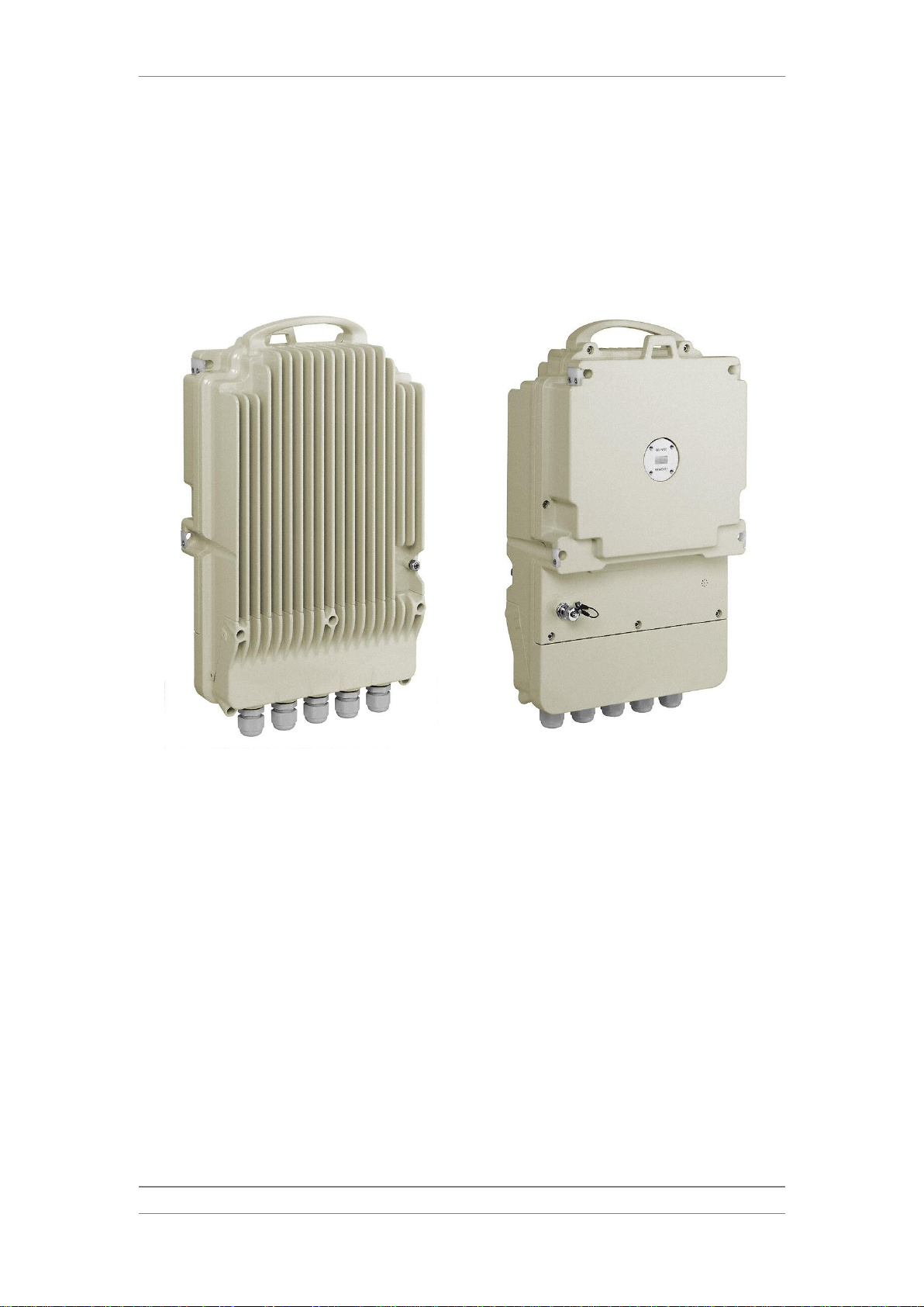
1. FibeAir IP-10C Overview .................................................................................. 9
2. General Installation Procedures.................................................................... 10
2.1 Required Tools for Installation ..................................................................................... 10
2.2 Transportation.............................................................................................................. 10
2.3 Packing Inspection....................................................................................................... 11
2.4 Location of the IP-10C ................................................................................................. 11
2.5 Installation Components............................................................................................... 12
2.6 Available Adapters and Installation Kits....................................................................... 13
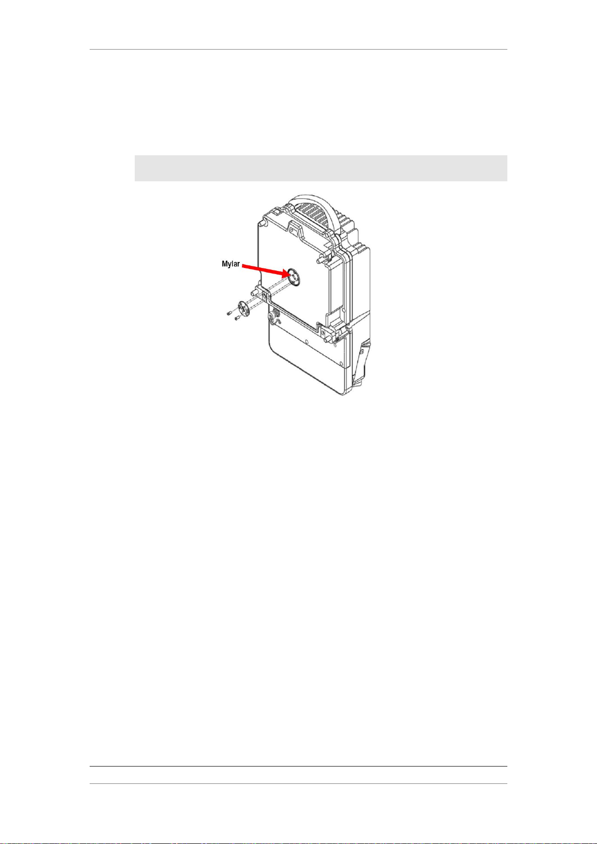
2.7 Antenna Connection..................................................................................................... 15
2.8 Adjusting for Horizontal and Vertical Polarization........................................................ 16
2.9 Connecting Flexible Waveguides to the IP-10C .......................................................... 17
2.9.1 Connecting the Waveguide in 6-13 GHz Bands .......................................................... 18
2.9.2 Connecting the Waveguide in 15-42 GHz Bands ........................................................ 18
2.10 Cable Connections and Grounding Procedure............................................................ 20
2.10.1Available Cable Options............................................................................................... 20
2.10.2SFP Options................................................................................................................. 20
2.10.3Accessory Kits.............................................................................................................. 20
2.10.4Cap and Gland Installation........................................................................................... 21
2.10.5Cable Installation –General......................................................................................... 22
2.10.6Preparing and Connecting a Cat5E Cable................................................................... 24
2.10.7Connecting SFP Cables............................................................................................... 27
2.10.8Connecting Bundled Cat5 Cable and Power Cable..................................................... 29
2.10.9Connecting the Power Cable ....................................................................................... 30
2.11 Securing the Cables..................................................................................................... 32
2.12 Grounding the Cables to the Antenna Tower Every 50m ............................................ 32
2.13 Grounding the IP-10C.................................................................................................. 33
2.14 Surge Protection .......................................................................................................... 34
3. IP-10C Configurations.................................................................................... 35
3.1 1+0 Direct Mount Installation ....................................................................................... 35
3.2 1+0 Remote Mount Installation .................................................................................... 36
3.3 1+1 HSB Direct Mount Installation............................................................................... 39
3.4 1+1 HSB Remote Mount Installation............................................................................ 42
3.5 2+0 Single Polarization (SP) Direct Mount Installation –Symmetrical Coupler .......... 44
3.6 2+0 Single Polarization (SP) Remote Mount Installation –Symmetrical Coupler ....... 48
3.7 2+0 Dual Polarization (DP) –Direct Mount Installation................................................ 50
3.8 2+0 Dual Polarization (DP) –Remote Installation ....................................................... 53

FibeAir® IP-10C Installation Guide
Ceragon Proprietary and Confidential Page 5 of 63
4. Remote Mount Installation with an Imperial Waveguide.............................. 56
4.1 Remote Mount Installation with an Imperial Waveguide –6-11 GHz .......................... 57
4.2 Remote Mount Installation with an Imperial Waveguide –13-15 GHz ........................ 58
4.3 Remote Mount Installation with an Imperial Waveguide –18-42 GHz ........................ 59
5. Appendix A: Mediation Device Losses ......................................................... 60
6. Appendix B: Test Kit Part Numbers.............................................................. 61
7. Appendix C: Connector Pin-Outs.................................................................. 62
7.1 Management Connector Pin-Out ................................................................................. 62
7.2 Power Connector Pin-Out............................................................................................ 62
7.3 Ethernet 10/100/1000 Connector Pin-Out.................................................................... 63
7.4 Craft Terminal Connector Pin-Out ............................................................................... 63

FibeAir® IP-10C Installation Guide
Ceragon Proprietary and Confidential Page 6 of 63
Safety Precautions & Declared Material
General Equipment Precautions
Use of controls, adjustments, or performing procedures other than those
specified herein, may result in hazardous radiation exposure.
Machine noise information order - 3. GPSGV, the highest sound pressure
level amounts to 70 dB (A) or less, in accordance with ISO EN 7779.
Static electricity may cause body harm, as well as harm to electronic
components inside the device.
Anyone responsible for the installation or maintenance of the IP-10C must use
an ESD Wrist Strap.
ESD protection measures must be observed when touching the RFU.
To prevent damage, before touching components inside the device, all
electrostatic must be discharged from both personnel and tools.
In Norway and Sweden:
Equipment connected to the protective earthing of the building installation
through the mains connection or through other equipment with a connection
to protective earthing –and to a cable distribution system using coaxial cable,
may in some circumstances create a fire hazard. Connection to a cable
distribution system has therefore to be provided through a device providing
electrical isolation below a certain frequency range (galvanic isolator, see EN
60728-11).
Utstyr som er koplet til beskyttelsesjord via nettplugg og/eller via annet
jordtilkoplet utstyr –og er tilkoplet et kabel-TV nett, kan forårsake brannfare.
For å unngå dette skal det ved tilkopling av utstyret til kabel-TV nettet
installeres en galvanisk isolator mellom utstyret og kabel- TV nettet.”
Translation to Swedish: ”Utrustning som är kopplad till skyddsjord via jordat
vägguttag och/eller via annan utrustning och samtidigt är kopplad till kabel-
TV nät kan i vissa fall medfőra risk főr brand. Főr att undvika detta skall vid
anslutning av utrustningen till kabel-TV nät galvanisk isolator finnas mellan
utrustningen och kabel-TV nätet.
!!
!!
!!

FibeAir® IP-10C Installation Guide
Ceragon Proprietary and Confidential Page 7 of 63
Précautions générales relatives à l'équipement
L’utilisation de commandes ou de réglages ou l'exécution de procédures
autres que celles spécifiées dans les présentes peut engendrer une
exposition dangereuse aux rayonnements.
Bruit de machine d’ordre - 3. GPSGV, le plus haut niveau de pression
sonore s'élève à 70 dB (A) au maximum, dans le respect de la norme ISO
EN 7779.
Allgemeine Vorsichtsmaßnahmen für die Anlage
Wenn andere Steuerelemente verwendet, Einstellungen vorgenommen
oder Verfahren durchgeführt werden als die hier angegebenen, kann
dies gefährliche Strahlung verursachen.
Maschinenlärminformations-Verordnung - 3. GPSGV, der höchste
Schalldruckpegel beträgt 70 dB(A) oder weniger gemäß EN ISO 7779.
!!
!!
!!
!!

FibeAir® IP-10C Installation Guide
Ceragon Proprietary and Confidential Page 8 of 63
About This Guide
This guide describes the IP-10C installation procedures and provides additional
information concerning system parts and installation procedures.
What You Should Know
The IP-10C is an all outdoor module, which is based on the FibeAir IP-10Q and
RFU-C systems. The IP-10C is part of Ceragon’s outdoor system, using the same
waveguide and accessories.
Target Audience
This guide contains technical information about IP-10C installation, and is
intended for use by qualified Ceragon technical personnel at all levels.
Related Documents
FibeAir IP-10C Product Description - DOC-00029987
FibeAir IP-10C User Guide –DOC-00035560
FibeAir IP-10C MIB Reference –DOC-00033230
FibeAir IP-10 License Management System - DOC-00019183
FibeAir CeraBuild Commission Reports Guide, DOC-00028133

FibeAir® IP-10C Installation Guide
Ceragon Proprietary and Confidential Page 9 of 63
1. FibeAir IP-10C Overview
FibeAir IP-10C is a state-of-the-art all-outdoor unit which is fully software
configurable and supports a broad range of capacities and interfaces.
IP-10C –Front View
IP-10C –Rear View
IP-10C provides a powerful, reliable, and comprehensive solution for a variety
of wireless network scenarios and requirements.

FibeAir® IP-10C Installation Guide
Ceragon Proprietary and Confidential Page 10 of 63
2. General Installation Procedures
This section provides instructions applicable for every IP-10C configuration.
Note: For all installation types, do not remove the transparent
pressure window (mylar) from the antenna interface.
2.1 Required Tools for Installation
The following tools are required for an IP-10C installation:
Ball head socket key wrench, metric set
Phillips screwdriver #1,#2
Slot screwdriver 0.5x3x100
Slot screwdriver 1.6x10x200
Locking Pliers with plastic teeth
Wrench 24mm
2.2 Transportation
The equipment should be prepared for public transportation. The cargo must
be kept dry during transportation, in accordance with ETS 300 019-1-2, Class
2.3.
It is recommended that the equipment be transported to the installation site
in its original packing case.
If intermediate storing is required, the packed equipment must be stored in a
dry and cool environment, and out of direct sunlight, in accordance with ETS
300 019-1-1, Class 1.2.

FibeAir® IP-10C Installation Guide
Ceragon Proprietary and Confidential Page 11 of 63
2.3 Packing Inspection
Check that the package is not damaged.
Check the packing lists and verify that the correct equipment part numbers
and quantities are found in the package that arrived.
Each IP-10C radio kit includes the following items:
IP-10C unit
2 Glands
5 Caps
Adapting bar kit
2 DC power connectors
2.4 Location of the IP-10C
Restricted Access Area: The IP-10C is intended for installation in a
Restricted Access Area.
Distance: The IP-10C shall be installed within 140 feet (42.67 meters) from
the building. Otherwise, Ethernet and other SELV connections will turn to
TNV.
The IP-10C shall be installed in accordance with the national code and
requirements of the country in which the IP-10C is being installed.
!!

FibeAir® IP-10C Installation Guide
Ceragon Proprietary and Confidential Page 12 of 63
2.5 Installation Components
The following figures show the main components used in the IP-10C
installation procedures.
IP-10C
Adapting Bar
V/H Twist
Coupler Holder with Coupler/OMT
Remote Pole Mount Kit

FibeAir® IP-10C Installation Guide
Ceragon Proprietary and Confidential Page 13 of 63
2.6 Available Adapters and Installation Kits
Description
6GHz
7-8GHz
10-11GHz
13GHz
15GHz
18GHz
23GHz
26GHz
28-31GHz
32GHz
38GHz
42GHz
RFU-C COUPLER KIT
RFU-C6-
CPLR-Kit
RFU-C7_8-
CPLR-Kit
RFU-
C10_11-
CPLR-Kit
RFU-C13-
CPLR-Kit
RFU-C15-
CPLR-Kit*0
RFU-C18-
CPLR-Kit*0
RFU-C23-
CPLR-Kit
RFU-C26-
CPLR-Kit
RFU-C28-
CPLR-Kit
RFU-C32-
CPLR-Kit
RFU-C38-
CPLR-Kit
RFU-C42-
CPLR_Kit
RFU-C SYMMETRICAL
COUPLERS KIT
NA
RFU-C7_8-
Sym-cplr-kit
NA
RFU-C13-
Sym-cplr-kit
RFU-C15-
Sym-cplr-kit
RFU-C18-
Sym-cplr-kit
RFU-C23-
Sym-cplr-kit
NA
RFU-C TWIST KIT
RFU-C6-
TWST-Kit
RFU-C7_8-
TWST-Kit
RFU-
C10_11-
TWST-Kit
RFU-C13-
TWST-Kit
RFU-C15-
TWST-Kit
RFU-C18-
TWST-Kit
RFU-C23_26-TWST-Kit
RFU-C28_32-TWST-Kit
RFU-C38-
TWST-Kit
RFU-C42-
TWST-Kit
RFU-C OMT KIT
RFU-C6-OMT-
DM-Kit
RFU-C7_8-
OMT-DM-Kit
RFU-
C10_11-
OMT-DM-Kit
RFU-C13-
OMT-DM-Kit
RFU-C15-
OMT-DM-Kit
RFU-C18-
OMT-DM-Kit
RFU-C23-
OMT-DM-Kit
RFU-C26-
OMT-DM-Kit
RFU-C28-
OMT-DM-Kit
RFU-C32-
OMT-DM-Kit
RFU-C38-
OMT-DM-Kit
RFU-C42-
OMT-DM-Kit
RFU-C ADAPTORS
OMT KIT
RFU-C6-OMT-
ADAPT
RFU-C7_8-
OMT-ADAPT
RFU-
C10_11-
OMT-ADAPT
NA
RFU-C SHORT OMT
KIT
RFU-C-OMT-SHORT-PLATE
Remote Mount
6GHz
7-8GHz
10-11GHz
13GHz
15GHz
18GHz
23GHz
26GHz
28-31GHz
32GHz
38GHz
42GHz
RFU-C REMOTE
MOUNT KIT
RFU-C-PoleMount
RFU-C ADAPTOR
REMOTE MOUNT KIT
RFU-C6-
RM_ADAPT
RFU-C7_8-
RM_ADAPT
RFU-
C10_11-
RM_ADAPT
RFU-C13-
RM_ADAPT
RFU-C WG Kit
Flx-WG-4FT-6
Flx-WG-4FT-
7_8
Flx-WG-4FT-
10_11
Flx-WG-3FT-
13
Flx-WG-3FT-
15
Flx-WG-3FT-18-26
Flx-WG-3FT-28-38
Flx-WG-3FT-
42

FibeAir® IP-10C Installation Guide
Ceragon Proprietary and Confidential Page 14 of 63
Antenna Circ.
Adapters for
OMT
6GHz
7-8GHz
10-11GHz
13GHz
15GHz
18GHz
23GHz
26GHz
28GHz
32GHz
38GHz
42GHz
Andrew
RFU-C6-OMT-
INT-A
RFU-C7_8-
OMT-INT-A
RFU-C10_11-
OMT-INT-A
RFU-C13-
OMT-INT-A
RFU-C15-
OMT-INT-A
RFU-C18-
OMT-INT-A
RFU-C23-
OMT-INT-A
RFU-C26-OMT-
INT-A
RFU-C28-
OMT-INT-A
RFU-C32-
OMT-INT-A
RFU-C38-OMT-
INT-A
RFU-C42-
OMT-INT-A
RFS 1FT
NA
NA
NA
RFU-C13-
OMT-INT-
1FT-R
RFU-C15-
OMT-INT-
1FT-R
RFU-C18-
OMT-INT-
1FT-R
RFU-C23-
OMT-INT-
1FT-R
RFU-C26-OMT-
INT-1FT-R
RFU-C28-
OMT-INT-
1FT-R
RFU-C32-
OMT-INT-
1FT-R
RFU-C38-OMT-
INT-1FT-R
NA
RFS 2-6FT
RFU-C6-OMT-
INT-2_6FT-R
RFU-C7_8-
OMT-INT-
2_6FT-R
RFU-C10_11-
OMT-INT-
2_6FT-R
RFU-C13-
OMT-INT-
2_6FT-R
RFU-C15-
OMT-INT-
2_6FT-R
RFU-C18-
OMT-INT-
2_6FT-R
RFU-C23-
OMT-INT-
2_6FT-R
RFU-C26-OMT-
INT-2_6FT-R
RFU-C28-
OMT-INT-
2_6FT-R
RFU-C32-
OMT-INT-
2_6FT-R
RFU-C38-OMT-
INT-2_6FT-R
NA
GD
RFU-C6-OMT-
INT-GD
RFU-C7_8-
OMT-INT-
GD
RFU-C10_11-
OMT-INT-GD
RFU-C13-
OMT-INT-
GD
RFU-C15-
OMT-INT-
GD
RFU-C18-
OMT-INT-GD
RFU-C23-
OMT-INT-GD
RFU-C26-OMT-
INT-GD
RFU-C28-
OMT-INT-GD
RFU-C32-
OMT-INT-GD
RFU-C38-OMT-
INT-GD
NA
Radio Waves
RFU-C6L-
OMT-INT-RW
/ RFU-C6H-
OMT-INT-RW
RFU-C7_8-
OMT-INT-
RW
RFU-C10_11-
OMT-INT-RW
RFU-C13-
OMT-INT-
RW
RFU-C15-
OMT-INT-
RW
RFU-C18-
OMT-INT-RW
RFU-C23-
OMT-INT-RW
RFU-C26-OMT-
INT-RW
RFU-C28-
OMT-INT-RW
NA
RFU-C38-OMT-
INT-RW
NA
Shenglu
RFU-C7_8-
OMT-INT-SH
RFU-C10_11-
OMT-INT-SH
RFU-C13-
OMT-INT-SH
RFU-C15-
OMT-INT-SH
RFU-C18-
OMT-INT-SH
RFU-C23-
OMT-INT-SH
RFU-C26-OMT-
INT-SH
Xian Putian
RFU-C6-
OMT-INT-X
RFU-C7_8-
OMT-INT-X
RFU-
C10_11-
OMT-INT-X
RFU-C13-
OMT-INT-X
RFU-C15-
OMT-INT-X
RFU-C18-
OMT-INT-X
RFU-C23-
OMT-INT-X
RFU-C26-
OMT-INT-X
RFU-C28-
OMT-INT-X
RFU-C32-
OMT-INT-X
RFU-C38-
OMT-INT-X
NA
Imperial to mm Transitions
6GHz
7-8GHz
10-11GHz
13GHz
15GHz
18GHz
23GHz
26GHz
28-31GHz
32GHz
38GHz
42GHz
RFU-C ADAPTOR KIT TO IMPERIAL
ANT.
ADPT_RFU-
C6-RM_Imp
ADPT_RFU-
C7_8-RM_Imp
ADPT_RFU-
C10_11-RM_Imp
ADPT_RFU-
C13-RM_Imp
ADPT_RFU-
C15-RM_Imp
ADPT_RFU-C18_26-RM_Imp
ADPT_RFU-C28_38-RM_Imp
NA
RFU-C ADAPTOR KIT TO IMP WG
ADPT_RFU-
C6-RM_mill
ADPT_RFU-
C7_8-RM_mill
ADPT_RFU-
C10_11-RM_mill
ADPT_RFU-
C13-RM_mill
ADPT_RFU-
C15-RM_mill
ADPT_RFU-C18_26-RM_mill
ADPT_RFU-C28_38-RM_mill
NA

FibeAir® IP-10C Installation Guide
Ceragon Proprietary and Confidential Page 15 of 63
2.7 Antenna Connection
IP-10C uses Andrew, General Dynamics, RFS, Shenglu and Xian Putian
antennas.
IP-10C can be mounted directly for all frequencies (6-42 GHz) using the
following antenna types (for integrated antennas, specific antennas PNs are
required):
Andrew: VHLP series
RFS: SB/SU series
Shenglu: SLC series
Xian Putian: WTC/WTG series
General Dynamics: HPS series
For remote mount installations, the following flexible waveguide flanges
should be used (millimetric). The same antenna type (integrated) as indicated
above can be used (recommended).
Other antenna types using the flanges listed in the table below may be used.
If a different antenna type (CPR flange) is used, a flange adaptor is required.
Please contact your Ceragon representative for details.
Note: Conductive grease must be applied to the screws that
connect the IP-10C to the antenna interface.
Frequency
Circ. WG
Diameter
Rect. WG Flange Des.
Radio Side (Remote)
Flange Des.
Flex WG Side A
Flange Des.
Flex WG Side B
Flange Des.
Antenna (Remote)
Flange Des.
Band
Range (GHz)
6(L/U) GHz
5.8-7.1
31.8mm
WR137
UDR70
PDR70
PDR70
UDR70
7/8 GHz
7.1-8.5
26mm
WR112
UBR84
PBR84
PBR84
UBR84
10/11 GHz
10.0-11.7
18mm
WR90
UBR100
PBR100
PBR100
UBR100
13 GHz
12.7-13.3
15mm
WR75
UBR120
PBR120
PBR120
UBR120
15 GHz
14.5-15.4
13.5mm
WR62
UBR140
PBR140
PBR140
UBR140
18 GHz
17.7-19.7
10.5mm
WR42
UBR220
PBR220
PBR220
UBR220
23 GHz
21.2-23.6
9mm
26 GHz
24.5-26.6
8mm
28-31GHz
27.3-29.5
7mm
WR28
UBR320
PBR320
PBR320
UBR320
32GHz
31.8-33.4
6.5mm
38GHz
37.0-40.0
5.5mm
42GHz
40.5-43.5
4.775mm
WR22
UG383/U
UG383/U
UG383/U
UG383/U

FibeAir® IP-10C Installation Guide
Ceragon Proprietary and Confidential Page 16 of 63
2.8 Adjusting for Horizontal and Vertical Polarization
Polarization changes in the IP-10C are made by adjusting the iris on the
antenna port.
Attach the iris using two M3 screws, according to the antenna polarization:
For horizontal polarization, locate the holes above and below the letter
“H” on the pins and fasten the two screws.

FibeAir® IP-10C Installation Guide
Ceragon Proprietary and Confidential Page 17 of 63
For vertical polarization, locate the holes above and below the letter
“V” on the pins and fasten the two screws.
Note: For 6 GHz, separate irises are used for vertical and
horizontal polarization. The vertical iris comes assembled
with the IP-10C. The horizontal iris (MA-1840-X,
IP-10C Twist 6Ghz Horizontal) is included in the IP-10C
package.
2.9 Connecting Flexible Waveguides to the IP-10C
For an IP-10C operating in bands of 6-13 GHz, a remote mount adaptor must
be used to connect a flexible waveguide.
For an IP-10C operating in bands of 15-42 GHz, you must remove the iris
before connecting a flexible waveguide to the antenna port.
The following table provides the marketing models for the remote mount
waveguide adaptor kits required, per frequency.
Freq (WG standard)
6HGz (UBR70)
7-8GHz (UBR84)
10-11GHz (UBR100)
13GHz (UBR120)
Remote Mount WG
adaptor kit
RFU-C6-RM_ADAPT
RFU-C7_8-RM_ADAPT
RFU-C10_11-RM_ADAPT
RFU-C13-RM_ADAPT
Remote Mount Kit
RFU-C-PoleMount

FibeAir® IP-10C Installation Guide
Ceragon Proprietary and Confidential Page 18 of 63
2.9.1 Connecting the Waveguide in 6-13 GHz Bands
1 Mount the remote adaptor and O-Ring to the pole mount using the four M5
flat screws supplied in the Remote Mount Adaptor kit, and tighten the
screws.
2 Connect the flexible waveguide to the remote mount adaptor. Use screws
(supplied with the waveguide kit) to fasten the waveguide.
2.9.2 Connecting the Waveguide in 15-42 GHz Bands
1 Remove the iris from the IP-10C (no adaptor is required for the 15-42 GHz
bands).
2 Connect the waveguide to the antenna adaptor interface (the interface
exposed by removing the iris). Use four screws (supplied with the
waveguide kit) to fasten the waveguide end to the antenna adapter
interface.

FibeAir® IP-10C Installation Guide
Ceragon Proprietary and Confidential Page 19 of 63
Note: It is normal for the flexible waveguide to reach the IP-10C at
an angle of approximately 45°, as shown in the figure below.

FibeAir® IP-10C Installation Guide
Ceragon Proprietary and Confidential Page 20 of 63
2.10 Cable Connections and Grounding Procedure
2.10.1 Available Cable Options
MARKETING P/N
DESCRIPTION
IP-10C_Eth_cbl_50m
IP10-C CAT5E CABLE
IP-10C_Eth_cbl_75m
IP10-C CAT5E CABLE
IP-10C_Eth_cbl_1m
IP-10C external Eth cable 1m
CAT5-4P-CABLE
CAT-5E 4X2X24AWG,DOUBLE JACKET UV RESISTANCE,100m cable
IP-10C_Bundled_cbl_50m
IP10-C BUNDLED CABLE
IP-10C_Bundled_cbl_75m
IP10-C BUNDLED CABLE
DC_CAT5E_Bundled_drum
Bundled cable drum, DC 2x18AWG, CAT5E 305M
Outdoor_DC_cbl_2x18AWG_drum
DC cable drum for installation up to 75m
Outdoor_DC_cbl_2x12AWG_drum
DC cable drum for installation beyond 75m
OP-MM-CBL-LC-LC-DPLX 100M OUT
Optical cable Multi Mode LC-LC 100m OUTDOOR
OP-MM-CBL-LC-LC-DPLX 75M OUT
Optical cable Multi Mode LC-LC 75m OUTDOOR
OP-MM-CBL-LC-LC-DPLX 50M OUT
Optical cable Multi Mode LC-LC 50m OUTDOOR
OP-SM-CBL-LC-LC-DPLX 100M OUT
Optical cable Single Mode LC-LC 100m OUTDOOR
OP-SM-CBL-LC-LC-DPLX 75M OUT
Optical cable Single Mode LC-LC 75m OUTDOOR
OP-SM-CBL-LC-LC-DPLX 50M OUT
Optical cable Single Mode LC-LC 50m OUTDOOR
2.10.2 SFP Options
SFP-GE-SX-EXT-TEMP
SFP optical interface 1000Base-SX,EXT-TE
SFP-GE-LX-EXT-TEMP
SFP OPTICAL 1000Base-LX,EXT TEMP
2.10.3 Accessory Kits
GBE_connector_kit
10 GBE connectors and protective rubber boots
IP-10C_Glands_x5_kit
2. 5 IP-10C glands kit
Table of contents
Popular Receiver manuals by other brands

Sirius Satellite Radio
Sirius Satellite Radio SV1 SIRIUS One User and installation guide

Exogal
Exogal Pulsar IR) user manual

Satrix
Satrix LNC Series quick start guide

Dual
Dual XVM279BT Installation & owner's manual

Sony
Sony STR-DA3300ES - Multi Channel Av Receiver operating instructions

Beninca
Beninca RR.1WBV operating instructions