8 of 52 cover.eclipse.mech - 1
2.1.1 Overview of encapsulated track installation
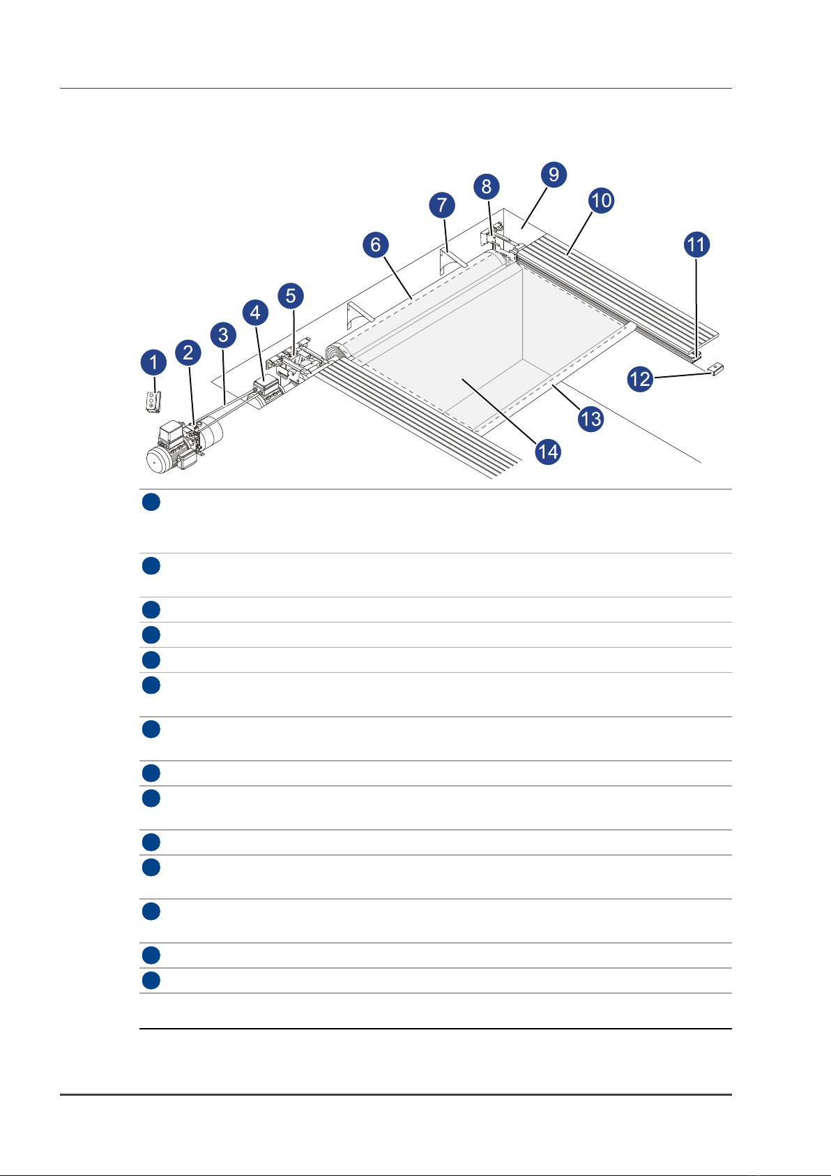
1Key switch Used to control opening and closing the cover. This switch can be locked.
The key switch must be located where the operator has full view of the pool
area while operating the cover.
2Hydraulic
power pack
The power pack must be positioned in a location where it is protected from
extreme temperatures, dust, water, condensation, and moisture.
3Hydraulic hoses Carries hydraulic fluid from power pack to the hydraulic motor.
4Hydraulic motor Part of the mechanism drive-end assembly.
5Mechanism Pulley system, gears, and rope wind and unwind reels. Drive-end assembly.
6Roller Roller for the cover. Note the direction of cover winding indicated on the
roller.
7Lid support
brackets
Brackets used to support the lid covering the roller pit. The amount and
installation pitch of the brackets depends on the lid type to be fitted.
8Mechanism Pulley system for rope wind and unwind. Non drive-end assembly.
9Roller pit Pit that houses the roller and mechanism assemblies. Refer to the pre-
installation manual for details
10 Coping Pool edging. This can be stone or decking type.
11 Encapsulated
track
Encapsulated track, inner guide, and spacer are installed as part of the pool
construction. Refer to the pre-installation guide for details.
12 Track pulley Used to return the rope inside the inner guide. Fitted to the end of each inner
track.
13 Lead edge bar Attached to the front of the cover fabric.
14 Cover Vinyl composite that covers the pool area.
Figure 1 - Overview of pit installation
Coverstar automatic safety pool cover - Installation Guide 2 Hardware description