Warrior MU-9X15
U104.4.0
List of Figures
Figure 1. Warrior System Receiver...............................................................................................2
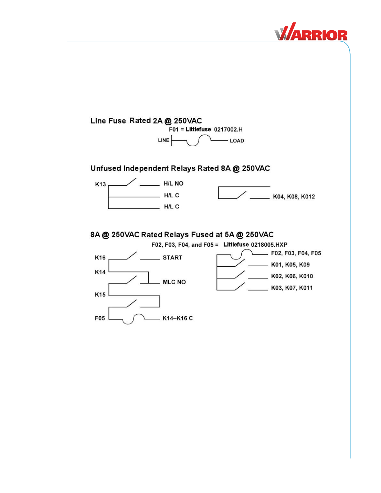
Figure 2. Bank Configuration ........................................................................................................3
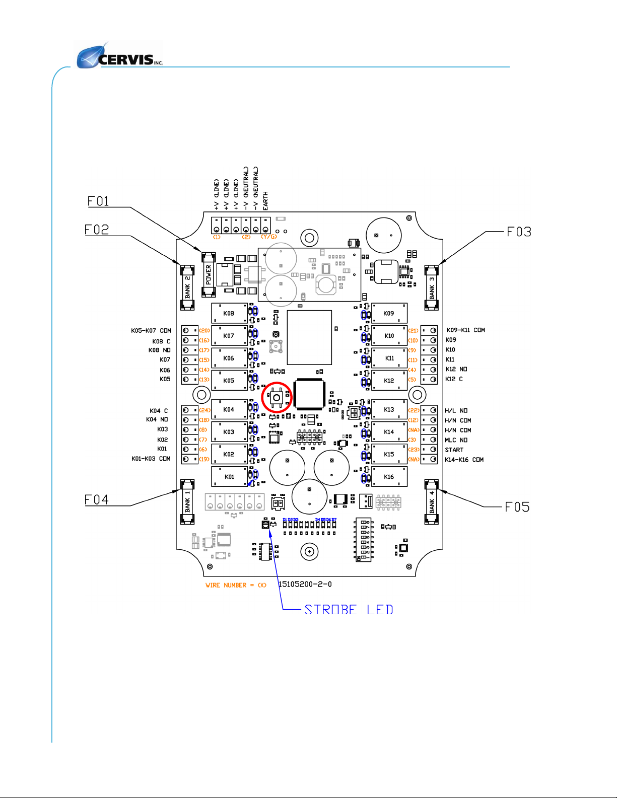
Figure 3. MU-9X15 LED Indicators & Relay Locations................................................................4
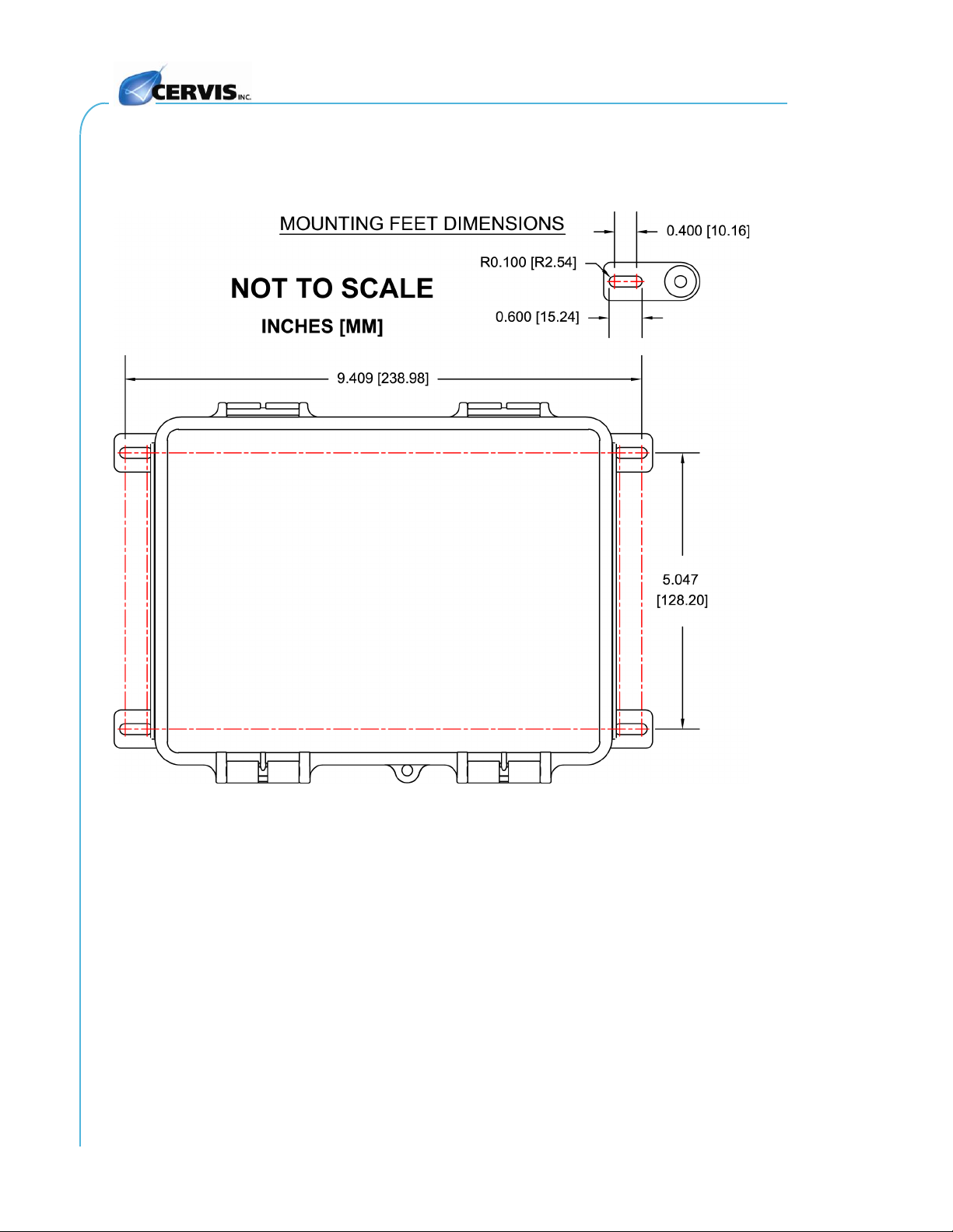
Figure 4. MU-9X15 Mounting Dimensions....................................................................................6
Figure 5. MU-9X15 900MHz External Antenna and Optional Extension Cables.......................7
Figure 6. MU-9X15 Wiring Diagram...............................................................................................8
Figure 7. MU-9X15 SW01 DIP Switch Assignments ....................................................................9
Figure 8. MU-9X15 MLC Safety Circuit Logic Diagram ............................................................ 15
List of Tables
Table 1. MU-9X15 Diagnostic LEDs ..............................................................................................5
Table 2. MU-9X15 Power Configurations......................................................................................7
Table 3. MU-9X15 Fuse Identification ...........................................................................................9
Table 4. Switches 1 and 2 Mode Configurations.........................................................................9
Table 5. DIP Switch 3: Applies to All Modes and All Transmitters............................................9
Table 6. DIP Switch 4: Applies to HH, Only Applies to Mode 00 or 01................................... 10
Table 7. DIP Switch 5: Only Applies to HH AND Only Applies to HH in Mode 00 or 01 AND
Only Applies if AB CYC/IND = 1................................................................................... 10
Table 8. DIP Switch 6: Only Applies in Mode 00 (HH: AB CYC/IND Needs Set to 0)............. 10
Table 9. DIP Switch 8: Applies to HH, Only Applies in Mode 00 or 01 ................................... 10
Table 10. MU-9X15 Relay Output Assignments........................................................................ 11
Table 11. Table 10 Abbreviation Key ......................................................................................... 11
Table 12. MU-9X15 Receiver Specifications.............................................................................. 13
Table 13.Warrior System Options.............................................................................................. 16
Definitions/Notes
Associate: When you program a transmitter with a receiver’s ID during the association process.
Pairing: When a transmitter takes control of a receiver for operation.
DSSS: Direct sequence spread spectrum; an advanced wireless communications technology.
Warrior Receiver: Receiver mounted to the crane or machine.
Line of Sight (aka Direct Line of Sight): Term used to describe RF communication where the
pathway between units is clear of physical obstacles such as walls, earth, or other obstructions.
RF: Wireless transmission and reception of data..
CAN TX/RX: Transmit and receive data over Control Area Network (CAN).
Transmitter: Handheld or portable unit.