Cervis Warrior MU-9X15 User manual

2019 Cervis, Inc.
™
MU-9X15 Manual
U104.6.0

Warrior MU-9X15
This document is the property of Cervis, Inc. and cannot be copied, modified, e-mailed, or reproduced without the express
prior written consent of Cervis, Inc.
Cervis, Inc. reserves the right to change this manual or edit, delete, or modify any information without prior notification.
FCC Statements
15.19 –Two Part Warning
This device complies with Part 15 of the FCC rules. Operation is subject to the following two conditions:
(1) This device may not cause harmful interference and
(2) This device must accept any interference received, including interference that may cause undesired operation.
15.21 –Unauthorized Modification
NOTICE: The manufacturer is not responsible for any unauthorized modifications to this equipment made by the user. Such modifications could
void the user’s authority to operate the equipment.
15.105(b) –Note:
This equipment has been tested and found to comply with the limits for a Class B digital device, pursuant to Part 15 of the FCC Rules. These
limits are designed to provide reasonable protection against harmful interference in a residential installation. This equipment generates, uses and
can radiate radio frequency energy and, if not installed and used in accordance with the instructions, may cause harmful interference to radio
communications. However, there is no guarantee that interference will not occur in a particular installation. If this equipment does cause harmful
interference to radio or television reception, which can be determined by turning the equipment off and on, the user is encouraged to try to
correct the interference by one or more of the following measures:
Reorient or relocate the receiving antenna.
Increase the separation between the equipment and receiver.
Connect the equipment into an outlet on a circuit different from that to which the receiver is connected.
Industry Canada Statement
This device complies with Canadian RSS-210.
The installer of this radio equipment must ensure that the antenna is located or pointed such that it does not emit RF field in excess of Health Canada limits
for the general population; consult Safety Code 6, obtainable from Health Canada’s website https://www.canada.ca/en/health-
canada/services/environmental-workplace-health/reports-publications/radiation/safety-code-6-health-canada-radiofrequency-exposure-guidelines-
environmental-workplace-health-health-canada.html.
Le présent appareil est conforme à la norme CNR-210 d'Industrie Canada.
L'installateur de cet équipement radio doit s'assurer que l'antenne est située ou orientée de façon à ne pas émettre un champ RF dépassant les limites de
Santé Canada pour la population générale; consulter le Code de sécurité 6, disponible sur le site Web de Santé Canada https://www.canada.ca/en/health-
canada/services/environmental-workplace-health/reports-publications/radiation/safety-code-6-health-canada-radiofrequency-exposure-guidelines-
environmental-workplace-health-health-canada.html.
Industry Canada Statement
This device complies with Industry Canada licence-exempt RSS standard(s). Operation is subject to the following two conditions: (1) this device may not
cause interference, and (2) this device must accept any interference, including interference that may cause undesired operation of the device.
Le présent appareil est conforme aux CNR d'Industrie Canada applicables aux appareils radio exempts de licence. L'exploitation est autorisée aux deux
conditions suivantes : (1) l'appareil ne doit pas produire de brouillage, et (2) l'utilisateur de l'appareil doit accepter tout brouillage radioélectrique subi, même
si le brouillage est susceptible d'en compromettre le fonctionnement.
IC Unlicensed Devices EIRP Statements for Removable Antennas
Part 1: Under Industry Canada regulations, this radio transmitter may only operate using an antenna of a type and maximum (or lesser) gain
approved for the transmitter by Industry Canada. To reduce potential radio interference to other users, the antenna type and its gain should be so
chosen that the equivalent isotropically radiated power (e.i.r.p.) is not more than that necessary for successful communication.
Partie 1 : Conformément à la réglementation d'Industrie Canada, le présent émetteur radio peut fonctionner avec une antenne d'un type et d'un gain maximal
(ou inférieur) approuvé pour l'émetteur par Industrie Canada. Dans le but de réduire les risques de brouillage radioélectrique à l'intention des autres
utilisateurs, il faut choisir le type d'antenne et son gain de sorte que la puissance isotrope rayonnée équivalente (p.i.r.e.) ne dépasse pas l'intensité
nécessaire à l'établissement d'une communication satisfaisante.
Part 2: This radio transmitter (LOBSRF-305) has been approved by Industry Canada to operate with the antenna type listed below with the
maximum permissible gain and required antenna impedance for each antenna type indicated. Antenna types not included in this list, having a
gain greater than the maximum gain indicated for that type, are strictly prohibited for use with this device.
Partie 2 : Cet émetteur radio (LOBSRF-305) a été approuvé par Industrie Canada pour fonctionner avec le type d'antenne indiqué ci-dessous avec le gain
maximal admissible et l'impédance d'antenne requise pour chaque type d'antenne indiqué. Il est strictement interdit d'utiliser avec cet appareil un type
d'antenne ne figurant pas dans cette liste ou ayant un gain supérieur au gain maximum indiqué pour ce type.

Manual
2019 Cervis, Inc.
i
Table of Content
Table of Content............................................................................................................................ i
List of Figures .............................................................................................................................. ii
List of Tables................................................................................................................................ ii
Definitions/Notes.......................................................................................................................... ii
Cervis, Inc. Safety Precautions .................................................................................................. 1
1.0 Warrior MU-9X15.................................................................................................................. 2
1.1 Warrior MU-9X15 Receiver............................................................................................... 2
2.0 Warrior MU-9X15.................................................................................................................. 3
2.1 Input Voltages................................................................................................................... 3
2.2 MU-9X15 Diagnostic LEDs............................................................................................... 4
2.3 MU-9X15 Mounting ........................................................................................................... 5
2.4 MU-9X15 Power................................................................................................................. 7
2.5 MU-9X15 External Antenna.............................................................................................. 7
2.6 MU-9X15 Cable and Field Wiring..................................................................................... 8
2.7 MU-9X15 Fuse Information .............................................................................................. 9
2.8 MU-9X15 DIP Switch Configurations .............................................................................. 9
2.9 MU-9X15 Mode Definitions............................................................................................... 9
2.10 MU-9X15 Relay-to-Mode Output Assignments ............................................................ 11
3.0 Warrior MU-9X15 Operation.............................................................................................. 12
3.1 System Startup................................................................................................................ 12
3.2 Associate the Warrior MU-9X15 with a Warrior Transmitter ...................................... 12
3.3 Additional Warrior Programming Features.................................................................. 12
3.3.1 Horn/Light (Associate) Relay ..................................................................................... 12
4.0 Warrior MU-9X15 Specifications....................................................................................... 13
Appendix A: Exposure to Radio Frequency Energy .............................................................. 14
Appendix B: RF Exposure Considerations ............................................................................. 14
Appendix C: MU-9X15 Safety Circuit ....................................................................................... 15
Appendix D: Warrior System Options...................................................................................... 16

Warrior MU-9X15
U104.6.0
ii
List of Figures
Figure 1. Warrior MU-9X15 System Receiver...............................................................................2
Figure 2. Bank Configuration ........................................................................................................3
Figure 3. MU-9X15 LED Indicators & Relay Locations................................................................4
Figure 4. MU-9X15 Mounting Dimensions....................................................................................6
Figure 5. MU-9X15 900MHz External Antenna and Optional Extension Cables.......................7
Figure 6. MU-9X15 Wiring Diagram...............................................................................................8
Figure 7. MU-9X15 SW01 DIP Switch Assignments ....................................................................9
Figure 8. MU-9X15 MLC Safety Circuit Logic Diagram ............................................................ 15
List of Tables
Table 1. MU-9X15 Diagnostic LEDs ..............................................................................................5
Table 2. MU-9X15 Power Configurations......................................................................................7
Table 3. MU-9X15 Fuse Identification ...........................................................................................9
Table 4. Switches 1 and 2 Mode Configurations.........................................................................9
Table 5. DIP Switch 3: Applies to All Modes and All Transmitters............................................9
Table 6. DIP Switch 4: Applies to Handheld, Only Applies to Mode 00 or 01........................ 10
Table 7. DIP Switch 5: Only Applies to Handheld AND Only Applies to Handheld in Mode 00
or 01 AND Only Applies if AB CYC/IND = 1............................................................. 10
Table 8. DIP Switch 6: Only Applies in Mode 00 (HH: AB CYC/IND Needs Set to 0)............. 10
Table 9. DIP Switch 8: Applies to HH, Only Applies in Mode 00 or 01 ................................... 10
Table 10. MU-9X15 Relay Output Assignments........................................................................ 11
Table 11. Table 10 Abbreviation Key ......................................................................................... 11
Table 12. MU-9X15 Receiver Specifications.............................................................................. 13
Table 13. Warrior System Options............................................................................................. 16
Definitions/Notes
Associate: When you program a transmitter with a receiver’s identity code (ID) during the
association process.
Pairing: When a transmitter takes control of a receiver for operation.
DSSS: Direct Sequence Spread Spectrum; an advanced wireless communications technology.
Warrior Receiver: Receiver mounted to the crane or machine.
Line of Sight (aka Direct Line of Sight): Term used to describe RF communication, where the
pathway between units is clear of physical obstacles such as walls, earth, or other obstructions.
RF: Radio Frequency; wireless transmission and reception of data.
CAN TX/RX: Transmit and receive data over Control Area Network (CAN).
Transmitter: Handheld or portable remote control unit.

Manual
Cervis, Inc. Safety Precautions
Read and follow all instructions.
Failure to abide by Safety Precautions may cause equipment failure, loss of authority
to operate the equipment, and personal injury.
Use and maintain proper wiring. Follow equipment manufacturer instructions.
Improper, loose, and frayed wiring can cause system failure, equipment damage, and
intermittent operation.
Changes or modifications made to equipment not expressly approved by the
manufacturer will void the warranty.
Equipment owner/operators must abide by all applicable Federal, State, and Local
laws concerning equipment installation and operation. Failure to comply could result
in penalties and could void user authority to operate the equipment.
Make sure that the machinery and surrounding area is clear before operating. Do not
activate the remote control system until certain that it is safe to do so.
Turn off the transmitter and disconnect power from the receiver before attempting
any maintenance. This will prevent accidental operation of the controlled machinery.
Use a damp cloth to keep units clean. Remove mud, concrete, dirt, etc. after use to
prevent obstructing or clogging the buttons, levers, wiring, and switches.
Do not allow liquid to enter the transmitter or receiver enclosures. Do not use high-
pressure equipment to clean a transmitter or receiver.
Disconnect the receiver before welding on the machine. Failure to disconnect the
receiver may cause destruction of or damage to the receiver.
Operate and store units only within the specified operation and storage temperatures
defined in this document’s specifications.
Keep high-energy radio frequency (RF) devices away from transmitters. Activating
high-power communication radios, for instance, in close proximity to transmitters can
cause interference and “false” circuit activation.
The Warrior MU-9X15 external antenna must be connected only as recommended by
Cervis, Inc. with parts recommended by Cervis, Inc. Under no circumstances can a
signal amplifier be used.
Do not key two-way radios while using the transmitter.

Warrior MU-9X15
U104.6.0
2
1.0 Warrior MU-9X15
The Warrior MU-9X15 is a low-cost, machine-mounted receiver intended for crane control. The
receiver is self-contained and prefigured, providing a no-touch solution. The unit is available in
900MHz for maximum flexibility and accepts control commands from a variety of Warrior
transmitters.
1.1 Warrior MU-9X15 Receiver
The MU-9X15 can accept connections from any Warrior transmitter that has the receiver identity
(ID) code stored in its memory. The MU-9X15 is limited to communicating with one transmitter at
a time on a first-come/first-serve basis. The rugged construction and relay output configurability
allows Warrior systems to be used in a wide variety of typical crane control applications.
Standard (DIP Switch Set) Configurations include:
Three-motion, Two-speed control with A/B Select configurations
Three-motion, Two-speed control with momentary or latching AUX functions
Three-motion, Two-speed control with “Four-wire” hoist set up
Four-motion, Two-speed control
Figure 1. Warrior MU-9X15 System Receiver with 900MHz External Antenna
Warrior MU-9X15 Features
16 Form A relays
900 MHz license-free operation
Designed to ICS 8 NEMA Crane Specification
Eight DIP switches allow for configurability
High VAC, Low VAC, and DC input ranges available
Operating temperature range: -13°F to 158°F (-25°C to 70°C)
Storage temperature range: -40°F to +176°F (-40°C to +80°C)
Manual
2019 Cervis, Inc.
3
2.0 Warrior MU-9X15
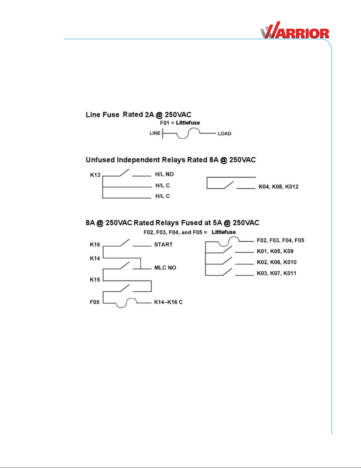
The MU-9X15 receiver features 16 Form A relays arranged in four banks of four. Bank 1 through
Bank 3 each have three relays, sharing a common fused at 5A; the fourth relay is independent
rated at 8A @ 250VAC. Bank 4 features one independent Horn/Light relay, two series relays
that form the Main Line Contactor (MLC) output, and one Start relay. The Start and MLC circuits
share a common fused at 5A. (See Appendix C for details regarding MLC safety logic.)
The independent relays (K13, K04, K08, and K12) are rated at 8A @ 250VAC.
Figure 2. Bank Configuration
2.1 Input Voltages
Depending on the model, the MU-9X15 accepts the following input voltages:
110 to 220VAC at 50–60 Hz (High VAC)
10 to 28VAC at 50–60Hz (Low VAC)
9 to 36VDC
0477002.MXP
0477005.MXP
Warrior MU-9X15
U104.6.0
4
2.2 MU-9X15 Diagnostic LEDs
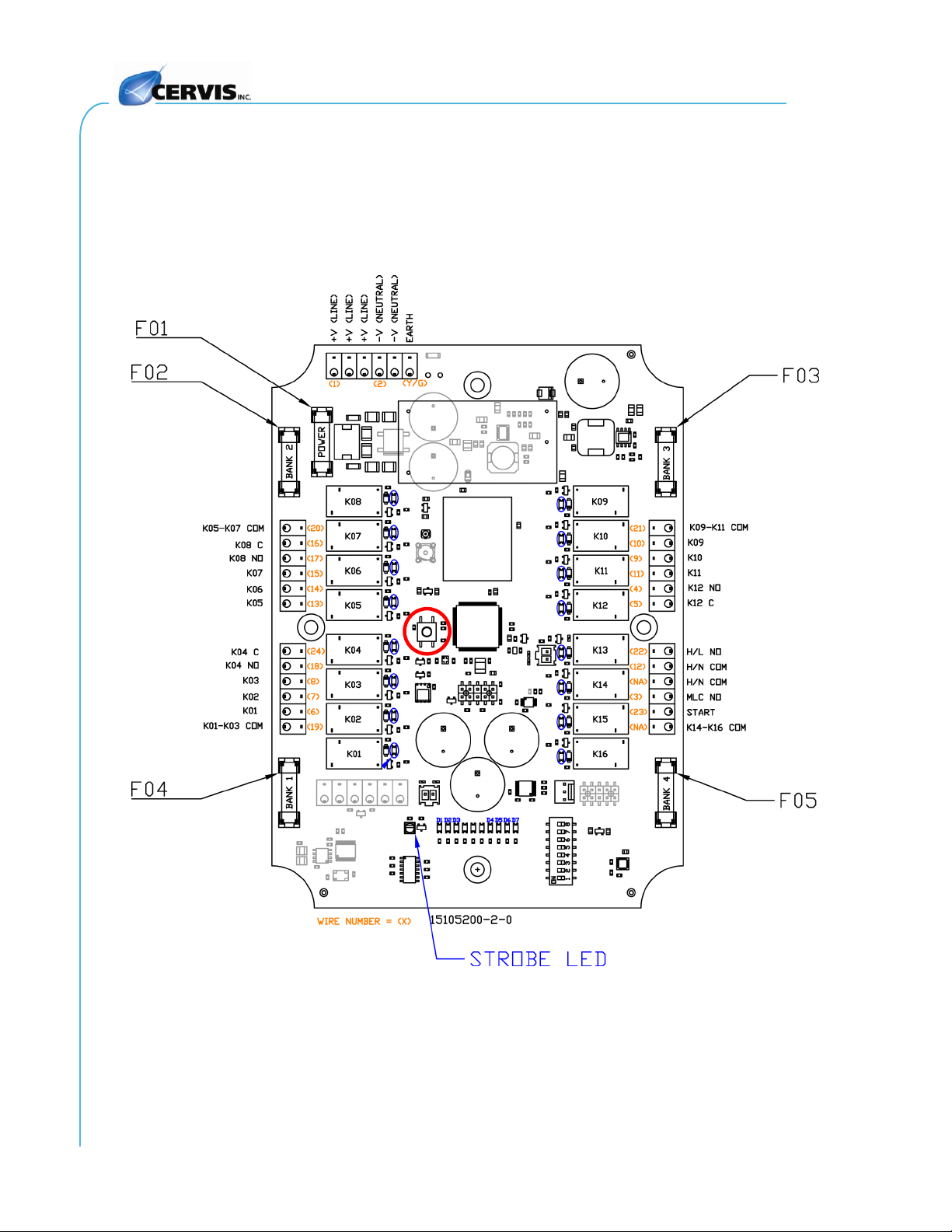
The MU-9X15 has three system status light-emitting diodes (LEDs), 16-relay status LEDs, and
four power LEDs that can be used as diagnostics tools (see Table 1). The MU-9X15 has one
internal LED indicator visible from outside the enclosure that is used for association and health
status. The strobe LED can be shut off for one hour by pressing the shut-off switch (see the RED
circle in Figure 3) and will reactivate either after one hour has passed or Association (Section
3.2) is performed.
Figure 3. MU-9X15 LED Indicators & Relay Locations
Manual
2019 Cervis, Inc.
5
Table 1. MU-9X15 Diagnostic LEDs
LED
Name
LED State
Description
1
Health
Blinking
Unit OK; normal processor operation
2
TX (Transmit)
Fast Blinking
Indicates RF Messages sent to transmitter
3
RX (Receive)
Fast Blinking
Indicates RF Messages received from
transmitter
4
Logic 3.3V
Lit Steady
Indicates Logic 3.3V bus OK
5
System 3.3V
Lit Steady
Indicates System bus 3.3V OK
6
RF 3.3V
Lit Steady
Indicates RF 3.3V bus OK
7
System 12V
Lit Steady
Indicates System 12V bus OK
LED per
Relay (16)
Relay State
Lit Steady
Relay Active
Each of the 16 relays has its own LED. When commanded, the relay LED illuminates.
2.3 MU-9X15 Mounting
Caution!
Before installing, disable the machine that the receiver will be
attached to to avoid injury.
Use the configuration diagrams that Cervis, Inc. supplied to guide you in mounting the receiver
and connecting your wire harness. Receiver mounting is left much to your discretion with the
following guidelines:
Make sure that the configuration diagrams supplied with the system are available. Keep
them where they can be easily accessed when needed.
Mount the receiver away from any intense radio or electric disturbance sources.
Mount the receiver where there is enough room to make wiring harness terminations.
Make sure the mount is secure.
The external antenna must be connected only as recommended by Cervis, Inc. with parts
recommended by Cervis, Inc. Under no circumstances can a signal amplifier be used.
Mount the receiver so that the operator can see the unit antenna. Apply an antenna
extension cable, if needed. Cervis, Inc. optional extension cables are 3ft. (J5-07), 10ft. (J5-
02), or 25ft. (J5-13). See Figure 5.
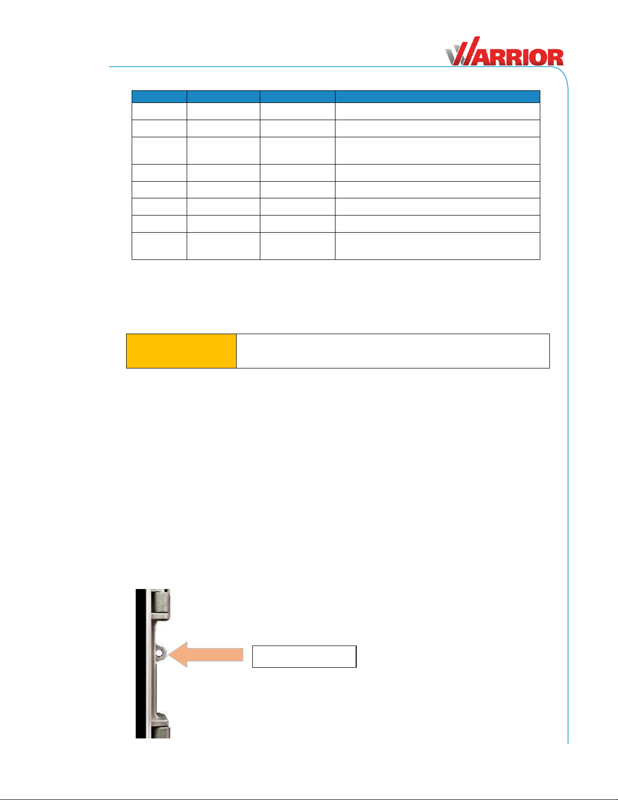
Note: As the MU-9X15 receiver owner, you are solely responsible for
ensuring secure access to it in its work environment. You may accomplish this by
attaching a simple lock-and-key or combination lock to the illustrated area.
Secure lock here.
Warrior MU-9X15
U104.6.0
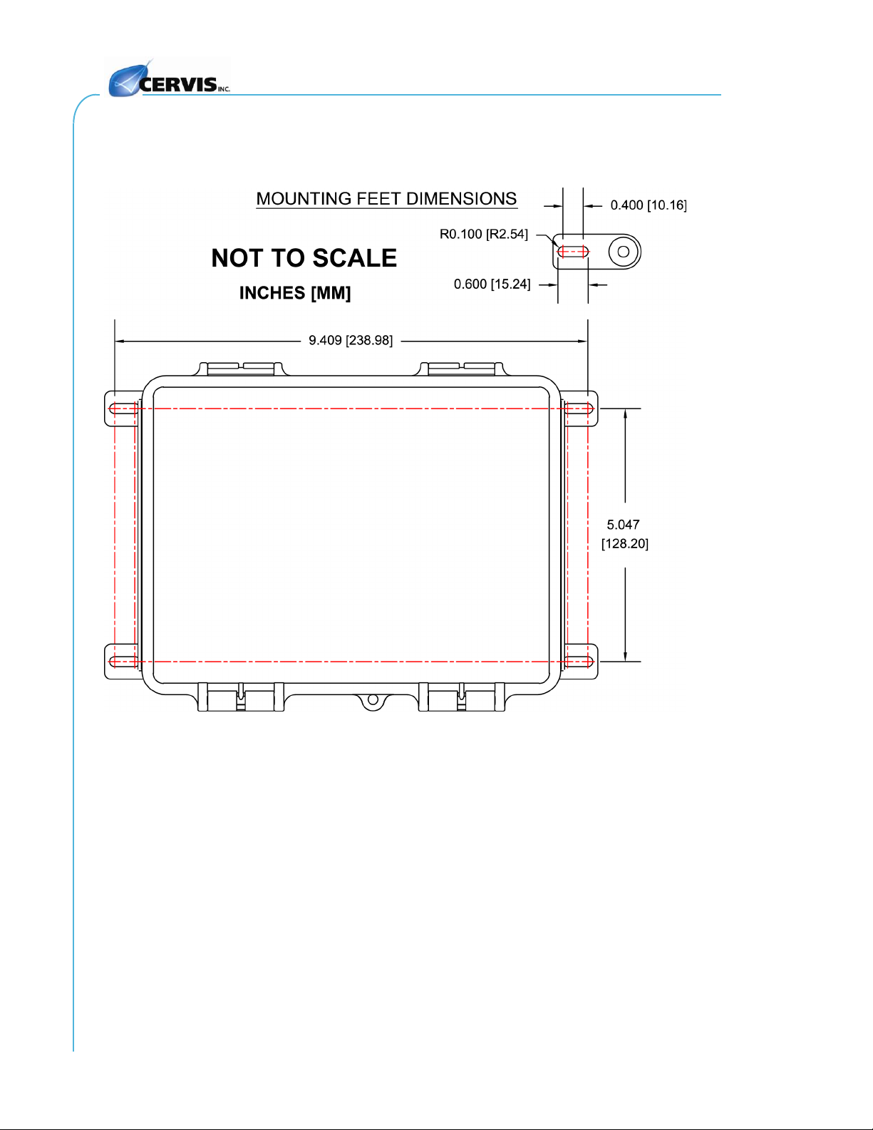
6
Figure 4. MU-9X15 Mounting Dimensions

Manual
2019 Cervis, Inc.
7
2.4 MU-9X15 Power
The unit receives power through the control cable. The cable is part of the final assembly and
comes attached to the receiver. The MU-9X15 is available in the input power configurations
listed in Table 2.
Table 2. MU-9X15 Power Configurations
Model
Input Voltage
Range
Frequency
MU-9X15-HVA
High Voltage AC
115−230 Vrms
50−60 Hz
MU-9X15-LVU
9−36VDC or 10−28Vrms
9−36VDC or 10-28 Vrms
50−60 Hz
2.5 MU-9X15 External Antenna
The Warrior MU-9X15 comes with a 900MHz external antenna that attaches to the receiver
using the external unit connector. Antenna extensions are available in 3-, 10-, and 25-foot
lengths.
Figure 5. MU-9X15 900MHz External Antenna and Optional Extension Cables
212mm (8.35")
Available
Extension Cables:
25' J5-13
10' J5-02
3' J5-07
External Antenna BB3-06
Warrior MU-9X15
U104.6.0
8
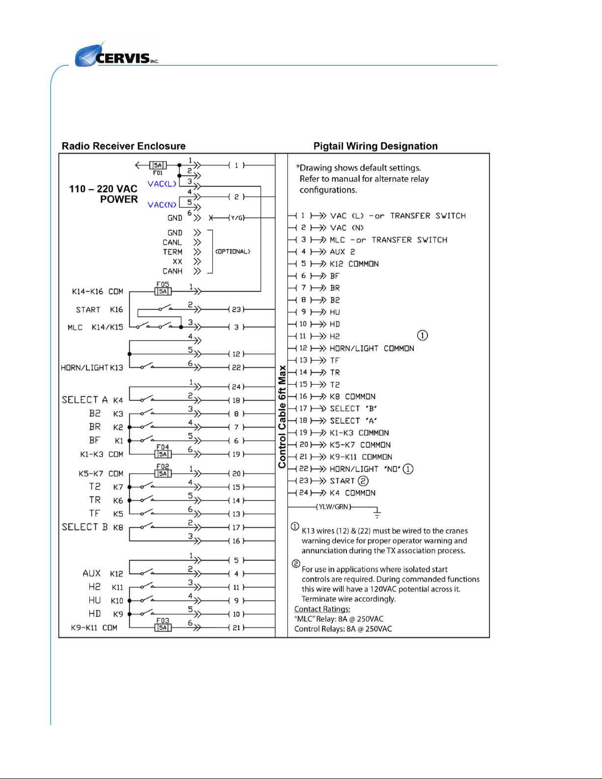
2.6 MU-9X15 Cable and Field Wiring
Note:The control cable is individually marked on each wire’s insulation. Note that negative
VDC (-VDC) should be connected directly to the power supply negative terminal.
Figure 6. MU-9X15 Wiring Diagram

Manual
2019 Cervis, Inc.
9
2.7 MU-9X15 Fuse Information
Use Table 3 to find replacement fuse part numbers based on your system’s rated input voltage
rating.
Table 3. MU-9X15 Fuse Identification
Model
Fuse Package
Bank 1-4 Fuse P/N
F01 Fuse P/N
MU-9X15-HVA
5x20 MM Glass
0477005.MXP
0477002.MXP
MU-9X15-LVU
5x20 MM Glass
0477005.MXP
0477002.MXP
2.8 MU-9X15 DIP Switch Configurations
The MU-9X15 uses eight DIP switches to allow for relay configuration of A/B cycling sequences,
configuring relays for three- or four-wire hoist control systems, configuration of Aux Relay A, and
configuration of Aux Relay B for momentary or latching control.
Figure 7. MU-9X15 SW01 DIP Switch Assignments
2.9 MU-9X15 Mode Definitions
Table 4. Switches 1 and 2 Mode Configurations
Mode
Definition
00
Three-Motion. Bridge, Trolley, and Hoist 3 relays. A, B, and AUX functions available.
01
Three-Motion. Bridge, Trolley 3 relays, Hoist 4 relays. A and B functions available, AUX
unavailable.
10
Three-Motion. Bridge, Trolley, Hoist 4 relays. A, B, and AUX functions unavailable.
11
Four-Motion. Bridge, Trolley, Hoist, 4th axis 3 relays. A, B, and AUX functions unavailable.
Table 5. DIP Switch 3: Applies to All Modes and All Transmitters
Name
Set
Definition
AB BOTH/OFF
0
Handheld (HH): Cycle pattern is A, B, Both.
Mini Console Box (MCB): Middle position of A/B switch is BOTH.
1
HH: Cycle pattern is A, B, Off.
MCB: Middle position of A/B switch is OFF.
ASOC
LOCK
AUX MOM
/ LAT
AB MOM
/ LAT**
A/B CYC
/ IND*
MODE
1
0
AB BOTH
/ OFF
UNUSED
*Applies only to handheld transmitter, only in MODE 00 and 01
**Applies only to handheld transmitter, only in MODE 00 and 01, only if SW4 = 1
Warrior MU-9X15
U104.6.0
10
Table 6. DIP Switch 4: Applies to Handheld, Only Applies to Mode 00 or 01
Name
Set
Definition
AB CYC/IND
0
HH: Button 9 cycles A/B (See AB BOTH/OFF).
MCB: No effect.
1
HH: Button 9 activates A, button 10 activates B, NO AUX (see AB MOM/LAT)
MCB: No effect.
Table 7. DIP Switch 5: Only Applies to Handheld AND Only Applies to Handheld in Mode 00 or
01 AND Only Applies if AB CYC/IND = 1
Name
Set
Definition
AB MOM/LAT
0
HH: A and B are momentary outputs.
MCB: No effect.
1
HH: A and B are latching outputs.
MCB: No effect.
Table 8. DIP Switch 6: Only Applies in Mode 00 (HH: AB CYC/IND Needs Set to 0)
Name
Set
Definition
AUX MOM/LAT
0
HH: AUX is momentary.
MCB: AUX is momentary.
1
HH: AUX is latching.
MCB: AUX is latching.
Table 9. DIP Switch 8: Applies to HH, Only Applies in Mode 00 or 01
Name
Set
Definition
ASOC LOCK
0
Association NOT permitted.
1
Association permitted.
Note: DIP switches may be changed at any time. However, changes will only be applied
when there is no active radio frequency (RF) connection.

Manual
2019 Cervis, Inc.
11
2.10MU-9X15 Relay-to-Mode Output Assignments
Table 10. MU-9X15 Relay Output Assignments
Relay
K1
K2
K3
K4
K5
K6
K7
K8
K9
K10
K11
K12
K13
K16
Mode
00
BF
BR
B2
A
TF
TR
T2
B
HD
HU
H2
AUX
A/H/L
ST
Mode
01
BF
BR
B2
A
TF
TR
T2
B
HD
HU
HD2
HU2
A/H/L
ST
Mode
10
BF
BR
BF2
BR2
TF
TR
TF2
TR2
HD
HU
HD2
HU2
A/H/L
ST
Mode
11
BF
BR
B2
4thR
TF
TR
T2
4thF
HD
HU
H2
4th2
A/H/L
ST
Table 11. Table 10 Abbreviation Key
Abbreviation Key
BF –Bridge Forward
BR –Bridge Reverse
B2 –Bridge Second Speed
A –Crane A Control
TF –Trolley Forward
TR –Trolley Reverse
T2 –Trolley Second Speed
B –Crane B Control
HD –Hoist Down
HU –Hoist Up
H2 –Hoist Second Speed
AUX –Auxiliary
A/H/L –Associate / Horn / Light
ST –Start/Horn
BF2 –Bridge Forward Second Speed*
BR2 –Bridge Reverse Second Speed*
HU2 –Hoist Up Second Speed
HD2 –Hoist Down second Speed*
TF2 –Trolley Forward Second Speed*
TR2 –Trolley Reverse Second Speed*
4thR –4th Axis Reverse
4thF –4th Axis Forward
4th2 –4th Axis Second Speed
*Used in four wire applications.

Warrior MU-9X15
U104.6.0
12
3.0 Warrior MU-9X15 Operation
3.1 System Startup
Startup depends on the type of Warrior handheld transmitter that the MU-9X15 receiver is
associated to. Refer to the Warrior transmitter manual for Startup details.
3.2 Associate the Warrior MU-9X15 with a Warrior Transmitter
Warrior system receivers and transmitters are associated (paired) before the system is shipped.
The Associate process is locked in the receiver by the MU-9X15 DIP switch 8 being set to 0
(OFF). The receiver will only communicate with transmitters it is associated to. When necessary,
other Warrior transmitters can be associated to the receiver as additional spares or to replace
damaged transmitters; but the receiver association ability must be first unlocked. Refer to the
specific Warrior transmitter for associate details.
3.3 Additional Warrior Programming Features
3.3.1 Horn/Light (Associate) Relay
Each Warrior receiver has a Horn/Light relay. Cervis, Inc. recommends properly wiring this relay
to some type of indicating device—such as a horn or light—that is easily recognized when
activated. When wired correctly, the operator will be alerted during the association process, and
the receiver communicating can easily be identified. The Horn/Light relay also identifies other
conditions.
Tilt Mode
If your Warrior transmitter has a Tilt Mode (see manual)—and it is tilted—the relay will begin
pulsing once per second after three seconds. The operator then has three seconds to correct the
tilt situation.
If the condition is not corrected in the three seconds that the relay is pulsing, the motion
outputs will be disabled; the crane should stop moving.
If the condition is corrected within the three-second period following the first indication of a
problem, normal crane operation resumes.
Low Battery Mode
When transmitter battery voltage drops to or below 2.2V (Low Battery Warning Mode), the
Battery LED (L2) begins flashing, and the Horn/Light relay energizes four times per minute
to alert you that the transmitter batteries need to be replaced with a fresh set.
Caution!
Replace transmitter batteries as soon as possible after the Low
Battery Warning begins. If the transmitter battery voltage drops to
2.0V, the transmitter shuts down and cannot be used until fresh
batteries are installed.
Associate Mode is Unlocked
If receiver DIP Switch 8 is in the unlocked position (1) when the receiver is powered on, the
Horn/Light relay will energize once to alert you to the unlocked Switch 8 position. Additional
transmitters can be associated with the receiver, if needed.
DIP Switch 8
The Horn/Light relay energizes once any time DIP Switch 8 is positioned from Off to On while
the receiver is under power.

Manual
2019 Cervis, Inc.
13
4.0 Warrior MU-9X15 Specifications
Table 12. MU-9X15 Receiver Specifications
Item
Description
Power (Vin)
MU-9X15-HVA 115 to 230 Vrms @ 50-60 Hz
MU-9X15-LVU 9−36VDC or 10−28 VAC @ 50–60 Hz
Environment
Operating Temp -13°F to 158°F (-25°C to 70°C)
Storage Temp -40°F to 176°F (-40°C to 80°C)
Humidity 0–95% non-condensing
Radio
Frequency 906–924 MHz @ 100mW
License No license required
Modulation Direct Sequence Spread Spectrum
(DSSS)
Antenna External (RP-TNC)
Enclosure
Dimensions mm: 200 x 150 x 100
Inches: 7.87 x 5.9 x 3.93
Weight 1.5 lbs.
Durability NEMA 1, 2, 4, 4X
IP65/67
LED Indicator
White Used during association
Control Relays
Function Nine Form A Relays, 8A @ 250VAC each
Three banks of three relays
each bank fused at 5A @ 250VAC
Main Line Contactor
(MLC)
Safety Circuit Two (series) Type Form A 8A @ 250VAC
Fused @ 5A @ 250VAC
Isolated Relays
Independent Four Form A, 8A @ 250VAC
Input Fuse
Line One 2A @ 250VAC

Warrior MU-9X15
U104.6.0
14
Appendix A: Exposure to Radio Frequency Energy
Warrior transmitter units and receivers contain radio transceivers. When active, a transmitter
sends out radio frequency (RF) energy through its internal antenna. Warrior transmitters and
receivers comply with limits set by the United States Federal Communications Commission
(FCC) for operating distance from human tissue.
Appendix B: RF Exposure Considerations
The transmitter module may be used in a variety of host applications that fall into two general
categories:
1. Mobile: Any operating locations that are not on a human body. In mobile
applications, the host application is typically fixed to mobile equipment, with
either an internal or external antenna.
2. Portable: Operating locations where the transmitting equipment is located on the
hand, arm, or other part of the human body. In portable applications, the
equipment is typically held in an operator’s hand or affixed to either a belt or
harness on the torso.
Equipment containing the radio module was evaluated for RF exposure hazards by two
approaches:
1. Maximum Permissible Exposure (MPE) for mobile applications.
2. Specific Absorption Rate (SAR) for portable applications.
The required separation distances are measured from the actual location of the radiating part of
the antenna. An antenna may be inside the host application, affixed to the host application
enclosure, or at the end of an optional extension coaxial cable.
Mobile Applications
Equipment must be located at least 20cm away from areas likely to be occupied by an unaware
person.
Handheld Applications
All operators of handheld equipment with any type of antenna require proper equipment
operation training, and such training must include RF exposure safety instructions. Once training
is completed, they are considered to be “aware”persons.
If the portable operating position is on the hand or arm, a 5mm separation between the radiating
part of the antenna and nearby human tissue is required.
Required Training
All installers and operators of host applications that include an SRF310 FT module must be
trained to use proper RF safety precautions as presented in this section.

Manual
2019 Cervis, Inc.
15
Appendix C: MU-9X15 Safety Circuit
Figure 8. MU-9X15 MLC Safety Circuit Logic Diagram
Figure 8 illustrates a high-level view of the system’s safety architecture. This architecture is
based around redundant enable signals that separate hardware circuits generate. The
microprocessor generates an enable signal to K14 when all conditions are met, and the user
activates the start sequence. The watchdog circuit generates an independent enable signal to
K15 as long as the microprocessor generates the proper signaling to the watchdog. Additionally,
these two independent enable signals are AND-ed together to enable an internal 12V bus that
supplies coil power to all relays
1
. The system cannot close any relay until both watchdog and
microprocessor enables are asserted. The loss of either signal immediately causes the MLC
path to open and all output relays to de-energize.
If there is a software fault in the microprocessor, the watchdog will not assert its enable output,
which will cause K15 to open. Additionally, this will disable the internal 12V bus, resulting in all
relay outputs returning to their non-active state, regardless of what the microprocessor is
commanding.
If there is a fault in the watchdog circuit that causes its output to never assert, the unit will be
safe as the MLC path cannot close because K15 will be open and the internal 12V bus will be
disabled. If the fault causes the watchdog circuit to never de-assert (perhaps the contacts on
K15 weld closed), the system is still safe because the microprocessor has independent control
of K14 that can break the MLC path and internal 12V bus.
This architecture was devised so that any one fault will not cause loss of control of the MLC
path.
1
Except the K13 H/L relay because it is necessary to operate the H/L when the MLC is open.
Warrior MU-9X15
U104.6.0
16
Appendix D: Warrior System Options
The following table lists available system options.
Table 13. Warrior System Options
Item #
Description
EXT-ANT10-1
10' antenna cable extension kit
Includes J5-02 (cable) and J5-12 (bracket/hardware)
EXT-ANT25-1
25' antenna cable extension kit
Includes J5-13 (cable) and J5-12 (bracket/hardware)
15114310
Green panel mount LED
15114311
HORN Mini 12VDC Onboard 90db Horn / Buzzer installed
15104112
Two-point mounting plate for receiver
HH2S-9XL10
Spare transmitter
HH2S-9XL10M
Spare transmitter with vibratory feedback motor
L152
Warrior alternative button label sheet
L154
Warrior 15100403 replacement handheld overlay
L159
Handheld Transmitter Warning Tag
15100110
Handheld transmitter “Work Safe” orange wrist breakaway
lanyard
07127150
Warrior handheld transmitter boot
07100376
Handheld transmitter battery door
AA8-015A
Handheld transmitter battery compartment sealing gasket
AA5-05
Handheld transmitter lanyard mounting pin
BB3-06
Receiver antenna
RCGHB
Charger and Four AAA Rechargeable Batteries
Table of contents
Other Cervis Receiver manuals


Popular Receiver manuals by other brands

DEVA Broadcast
DEVA Broadcast DB7000 Maintenance and operating instructions

TrekStor
TrekStor SatCorder Neptune operating instructions

BWI Eagle
BWI Eagle AIR-EAGLE XLT Product information bulletin

Nitek
Nitek EtherStretch Lyte ER8200C Installation and operation manual

Williams Sound
Williams Sound SoundPlus Infrared Receiver WIR RX3 Specification sheet

Onkyo
Onkyo HT-S5600 Manuel d'instructions


