Ceyear 87230 Series User manual

87230 Series
USB CW Power Sensor
Quick Start Guide


This manual is applicable to the following types of USB CW power sensors:
87230: 9 kHz ~ 6 GHz.
87231: 10 MHz ~ 18 GHz.
87232: 50MHz ~ 26.5GHz.
87233: 50MHz ~ 40GHz.
Options:
English options: English menu and English interface, for Export models
Version: A.1 March 2018, China Electronics Technology Instruments Co., Ltd
Address: No.98, Xiangjiang Road, Qingdao City, China
Tel: +86-0532-86896691
Website: www.ceyear.com
E-mail: sales@ceyear.com
Postal code: 266555

Foreword
Thank you for choosing and
using the 87230 series CW
power sensor researched and
produced by China Electronics
Technology Instruments Co.,
Ltd! Our product is high-end,
precise and sophisticated, and
embraces a high cost
performance among the
competitors of the same class.
We are devoted to providing for
you high-quality products and
first-class after-sales service
with your most concerns and
demands in mind. Our
consistent aim is providing
excellent quality and good
service, and this is our sincere
commitment for all users.
Manual No.
AV2.984.1215SK
Version
A.1 2018.03
China Electronics Technology
Instruments Co., Ltd.
Manual Authorization
This manual may be subject to
change without notice. CETI
reserves all the rights to the
final explanation for all the
information and terminologies
referred to in this manual.
This manual is the property of
CETI. Without CETI's
permission, any organizations
or individuals shall neither alter
nor duplicate/transmit this
manual for profits; otherwise,
CETI reserves the right to
pursue any liabilities therefrom.
Product Warranty
The warranty period of this
product is 18 months from the
date of delivery. Instrument
manufacturer will repair or
replace the damaged parts
according to the actual
situation in the warranty period.
The specific maintenance
matters should be subject to
the contract.
Product Quality Certification
This product is certified to fulfill
the standards indicated in this
manual from the day of delivery.
Calibration measurements
have been carried out based on
national standards. Related
information is available to the
user for reference.
Quality/environment
management
The quality and environmental
management systems have
always been implemented
during development,
manufacturing and test of this
product. China Electronics
Technology Instruments Co.,
Ltd. is properly qualified and
certified by ISO 9001 and ISO
14001 management system
standards.
Safety Precautions
"Caution" indicates a danger. It
reminds the user to be cautious
of a certain operation process,
operation method or the similar.
Failure to follow the rules or
operate correctly may result in
the minor or moderate personal
injury and equipment damage.
The conditions indicated by
CAUTION should be fully
understood and met before the
next operation.
CAUTION indicates an
important information rather
than danger. It reminds the
user to be cautious of a certain
operation process, operation
method or the similar. Failure to
follow the rules or operate
correctly may cause the
damage to the instrument or
loss of important data. The
conditions indicated by
CAUTION should be fully
understood and met before the
next operation.
ATTENTION
CAUTION
!


87230 Series USB CW Power Sensor
Table of Contents
1
Table of Contents
1 About This Manual.............................................................................................................................. 1
1.1 About This Manual................................................................................................................ 1
1.2 Related Documents.............................................................................................................. 1
2 Preparation before use....................................................................................................................... 3
2.1 Preparation before Operation............................................................................................... 3
2.2 Routine Maintenance.......................................................................................................... 10
3 Typical Applications.......................................................................................................................... 12
3.1 Selection of Power Sensor................................................................................................. 12
3.2 Virtual Power Measurement Panel..................................................................................... 12
3.3 Zeroing and Calibration Before Measurement................................................................... 14
3.4 CW Power Measurement................................................................................................... 15
4 Getting Help...................................................................................................................................... 18
4.1 Fault Diagnosis and Troubleshooting................................................................................. 18
4.2 Error Information................................................................................................................. 19
4.3 Repair Methods.................................................................................................................. 19


1 About This Manual
1.1 About This Manual
1
1 About This Manual
This chapter introduces the functions, compositions, and main content in the User’s Manual of the 87230
Series USB CW Power Sensor as well as other related documents provided to the user.
About This Manual…………………………………………………………………………… .................... 1
Related Documents……………………………………………………………………………................... 1
1.1 About This Manual
This manual introduces the basic functions and operation methods of the 87230 series USB CW power
sensor. This manual introduces the features, basic usage, measurement configuration guides, remote
control, maintenance and specifications of the instrument to help you familiarize yourself with and
master the operation methods and essentials as soon as possible. To facilitate your familiarity with the
instrument, please read this manual carefully before operating the instrument, and then follow the
instructions of manual.
The chapters included in this User's Manual are as follows:
Preparation before Use
This chapter introduces the pre-operation inspection of 87230 series CW power sensor to enable the
user to get ready for the correct and safe operation of the instrument.
Typical Applications
This chapter introduces operation methods of all functions of the instrument, including sensor selection,
virtual panel introduction, zero and calibration before measurement and continuous wave power
measurement, which is intended to make users understand and master some basic operation methods
of the 87230 series USB CW power sensor.
Getting Help
This chapter includes basic fault diagnosis, solution, error information description, and repair methods.
1.2 Related Documents
The product document related to 87230 series USB CW power sensor includes:
Quick Start Guide
User Manual
Programming Manual
Quick Start Guide
This manual introduces the settings of the instrument as well as the basic operating methods of
measurement with the aim of enabling users to quickly understand the features and basic local and
remote control operation of the instrument. Main chapters included in this manual are as follows::
About This Manual
Preparation before Use
Typical Applications
Getting Help
User Manual
This manual gives a detailed introduction of features and operation methods of the instrument, including
information about configuration, measurement, remote control, maintenance, etc. so as to provide users
with an all-round understanding of the features of the instrument and aid users in learning the most
common test procedures. Main chapters included in this manual are as follows::
About This Manual

1 About This Manual
1.2 Related Documents
2
Overview
Start Guide
Operation Guide
Remote Control
Fault Diagnosis and Repair
Technical specifications
Programming Manual
This manual describes the basics of remote control programming, basics of SCPI, SCPIs, examples of
programming, and I/O driver library, for the purpose of guiding the user to master the SCPIs and
methods of the instrument quickly and comprehensively. Main chapters included in this manual are as
follows::
About This Manual
Remote Control
SCPI
Programming Examples
Error Description
Appendixes

2 Preparation before use
2.1 Preparation before Operation
3
2 Preparation before use
This chapter introduces the precautions and routine maintenance before use of the 87230 series USB
CW power sensor to facilitate the user to have a preliminary understanding of the instrument. The
content contained in this chapter is consistent with that in relevant chapters of Quick Start Guide.
Preparations before operation…………………………………………………………………… ............. 3
Routine Maintenance………………………………………………………………………………........... 10
2.1 Preparation before Operation
This chapter introduces the precautions before the first use of the 87230 series USB CW power sensor.
Damage prevention
To avoid the electric shock, fire and personal injury:
Do not open the chassis without authorization;
Do not attempt to dismantle or modify any part not described in this manual. Improper removal may
cause the deterioration of electromagnetic shielding effectiveness, damage of internal parts, etc.
and affect the reliability of product. If the product is under warranty, we will no longer provide the
unpaid repairs.
Please carefully read relevant content of “2.2 Safe Use Guideline” of the User’s Manual and the
following precautions for safe operation. In addition, attention shall be paid to relevant specific
operating environment requirements specified in the reference data page.
During instrument operation, please pay attention to the following aspects:
Improper application site or measurement setting will damage the instrument or the connecting device.
Before powering on the instrument, please pay attention to the followings:
Keep the instrument dry;
Place the instrument horizontally and reasonably;
Ensure that the surrounding temperature is in accordance with the requirements on the reference
data page.
Ensure that the power level of the port input signal conforms to the mark range;
Ensure that the signal output port is properly connected and isn't overloaded.
ESD protection
Pay attention to the ESD protection measures in the workplace to avoid the damage to instrument. For
details, please refer to relevant content of “2.2 Safe Use Guideline” of the User’s Manual.
Attention
WARNING
!
ATTENTION
2 Preparation before use
2.1 Preparation before Operation
4
Effect of electromagnetic interference (EMI):
The electromagnetic interference can affect the measurement results, therefore, it is necessary to:
Select appropriate shielded cables, for example, use RF shielded twisted pair/network connection
cable;
close the opened and temporarily unused cable connection port or connect the matched load to the
connection port in time;
Refer to the electromagnetic compatibility (EMC) grade in the User’s Manual.
2.1.1 Unpacking
1) Visual inspection
Step 1. Check if there is any damage in the outer packaging and the anti-vibration packaging of the
instrument. If no damage is found, keep the packaging in case of future need and continue the
inspection
as per the following steps;
Step 2 Unpack the instrument and check for any damage to the main unit and attached items.
Step 3. Verify the items in the packaging box carefully by cross-checking with Table 2.1;
Step 4. If the outer package is broken, the instrument or accessories are damaged or there is any error
of the delivery, it is strictly forbidden to switch on the instrument! Please contact our service center via
the service hotline indicated on the cover,
Please contact our service consultation center through the service consultation hotline, and we will make
repairs and replacements rapidly based on individual circumstances.
2) Model confirmation
Table 2.1 Packing List of 87230 Series
Name
Quantity
Function
Main unit:
87230 series
1
Main unit
Standards:
USB cable
1
Special lockable USB cable, 2 m
CD
1
Including virtual panel, programming manual, driver, and
programming example
User Manual
1
—
Certificate of Conformity
1
Attached on the body
NOTE
2 Preparation before use
2.1 Preparation before Operation
5
2.1.2 Environment requirements
The operating place of the 87230 series USB CW power sensor shall meet the following environment
requirements.
1) Operating environment
The operating environment should satisfy the following requirements:
Table 2.2 Operating Environment Requirements of the 87230 Series
Temperature
10°C ~ 40°C
Temperature range during
error adjustment
23°C ±5°C (allowed temperature deviation during error adjustment<1°C)
Humidity
Hygrometer measurement range: 20% ~ 80% (uncondensed) when the
temperature<+29°C
Altitude
0 ~ 4,600 m
Vibration
Maximum: 0.21 G, 5 Hz ~ 500 Hz
The above environmental requirements are only defined for the operating environment of the instrument
and are not within the scope of specifications.
2) ESD protection
The static electricity is destructive to electronic components and equipment. Generally, we will use two
anti-static measures, including combination of conductive table mat and wrist combination as well as
combination of conductive floor mat and ankle strap. If these two combinations are used together, a
good anti-static protection can be provided. If the combination is used separately, only the former can
provide protection. For the safety of users , anti-static components must provide an isolation resistance
of at least 1 MΩ to the ground.
Please correctly use the following anti-static measures to reduce electrostatic damage:
Ensure that all instruments are properly grounded to avoid generating static electricity;
Before connecting the coaxial cable to the instrument, contact its inner and outer conductors with
the ground temporarily;
The staff shall wear anti-static wrist straps or adopt other anti-static measures before contacting
joints and core wires or carrying out any assembly operation.
Operating voltage range
The above anti-static measures can’t be taken in a place where the voltage exceeds 500 V.
ATTENTION
WARNING
!
2 Preparation before use
2.1 Preparation before Operation
6
2.1.3 Power on/off
1) Host system requirements
The 87230 series USB CW power sensor shall be applied with the standard USB mini-AB socket, and
shall be subject to power display or direct remote control on the computer or other test instrument with
USB host interface.
Before using the USB CW power sensor, please ensure that the host satisfies the following
requirements:
The computer or any hardware device with a USB host interface;
Support Windows98SE/ME/XP/2000/2003/Win7/WIN10 or higher version;
The host is installed with the version above VISA3.0 and the virtual power test panel provided along
with the machine;
It is also available for programming through the remote programming software including Microsoft®
Visual Basics, C++ and LabVIEW.
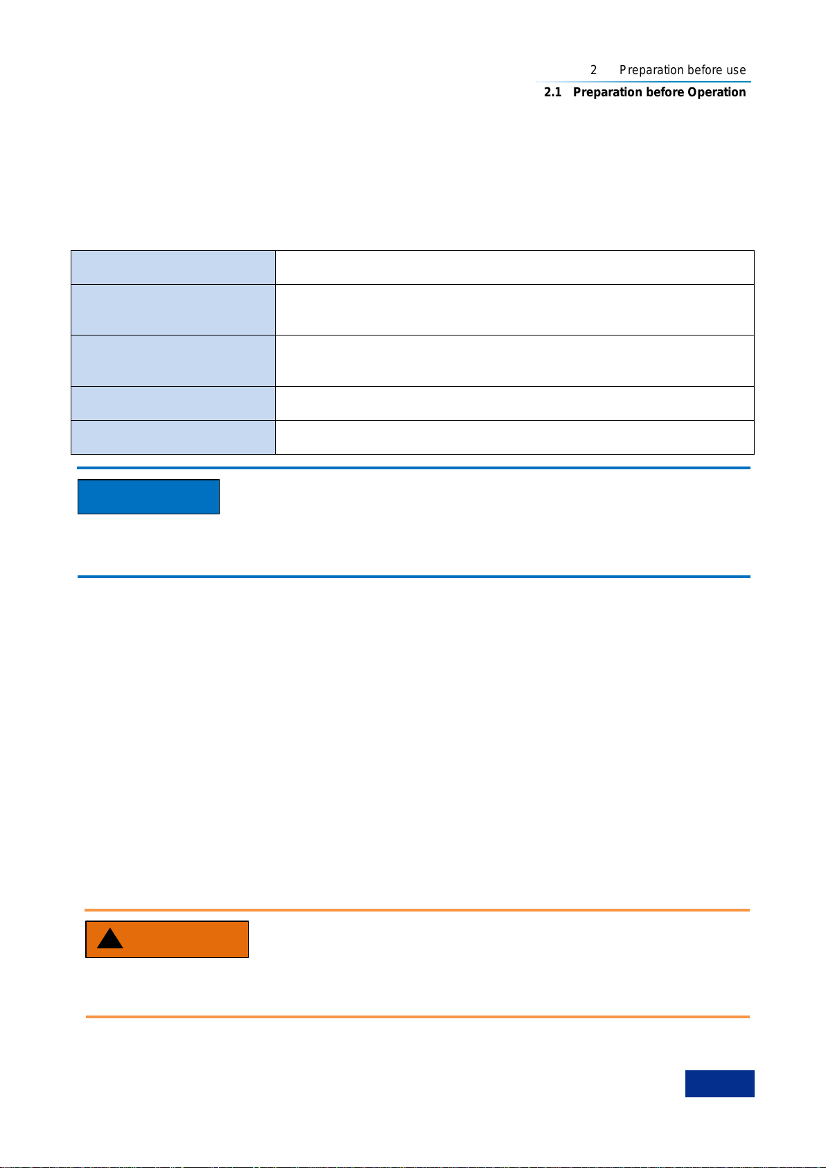
2) USB cable selection
The 87230 series USB CW power sensor is equipped with special USB cable, which can be screwed
and fixed on the body, as shown in Fig. 2.1. The user can also use his own USB cables, but shall ensure
that cables satisfy the international safety standards.
Prevent personal injury and damage to the instrument.
Poor contact or wrong wiring may lead to instrument damage or even personal injury. Therefore, the
users are recommended to use the USB cable provided by us. If other non-standard cables shall be
used, please contact our technical personnel.
Fig. 2.1 Fixable USB Cable
3) Charge of the instrument
The 87230 series USB CW power sensor is applied with the computer standard USB interface. Table 2.3
lists the power supply requirements of the 87230 series USB CW power sensor during normal operation.
WARNING
!
Fixed nut
Sealing ring
Mini USB connector

2 Preparation before use
2.1 Preparation before Operation
7
Table 2.3 Variation Range of Working Power Supply of the 87230 Series
Power Supply
Parameter
Applicable Scope
Output voltage
+5 V ±5% DC
Rated current
0.5A
The normal power consumption of the 87230 series USB CW power sensor is 1.8 W. When the
computer USB interface is inserted with multiple USB devices and it can’t guarantee that each interface
can provide 0.5A output current, the computer will prompt that some sensors can’t be found. In this case,
please use the USB HUB with external power supply.
Connect the sensor with the USB port of the host with the USB cable conforming to the requirements,
and observe whether the green indicator lamp of the sensor is lit up.
Step 1. Connect the small port of the USB cable with the 87230 series USB CW power sensor and
tighten it, and then connect its large port with the computer or measurement instrument USB host
interface, and the power sensor green indicator lamp will light up later;
Step 2. The “Equipment Manager” of the host can find the new “USB Test and Measurement Devices”.
Fig. 2.2 Connecting the USB CW power sensor to the Computer
4) Power off
Remove the USB cable to turn off the USB CW power sensor. In this case, the green LED indicator lamp
will go out.
2.1.4 Correct Use of Connectors
During test of the USB CW power sensor, it shall be connected to the USB cable and then connected to
the source to be tested. The 1.85 mm, 2.4 mm and 3.5 mm male connectors shall be used, and even
different types of switching adapters shall be used. Even though connectors are designed and
manufactured according to the highest standards, their service life is limited. Wear is unavoidable in
normal use and can make the connector performance degrade or even unable to meet the measurement
requirement, therefore, correct maintenance and measurement connections not only provide accurate
and repeatable measurement results but also prolong the useful life, reduce the measurement cost.

2 Preparation before use
2.1 Preparation before Operation
8
Note the following aspects during actual use:
1) Check of connectors
It is necessary to wear an anti-static wrist strap when checking the connectors. It is recommended to use
a magnifier to check:
1) the electroplated surface for wear and deep scratches;
2) the thread for deformation;
3) the thread and joint surface for metallic particles;
4) the inner conductor for bending and breakage;
5) the screw for improper rotation.
Check the connectors so as not to damage the instrument ports
Any damaged connector may damage the good connector connected to it even for the first time of
measurement. To protect the ports of the USB CW power sensor, the connector to be used shall be
checked before connection.
2) Connection
The connectors should be checked and cleaned before measurement and connection to ensure that
they are clean and undamaged. It is necessary to wear an anti-static wrist strap during connection. The
correct connection methods and procedures are as follows:
Step 1. As shown in Figure 2.3, align the axes of the two interconnected connectors to ensure that the
pin of the male connector slides concentrically into the hole of the female connector.
Fig. 2.3 CoaxialAlignment of Interconnected Connectors
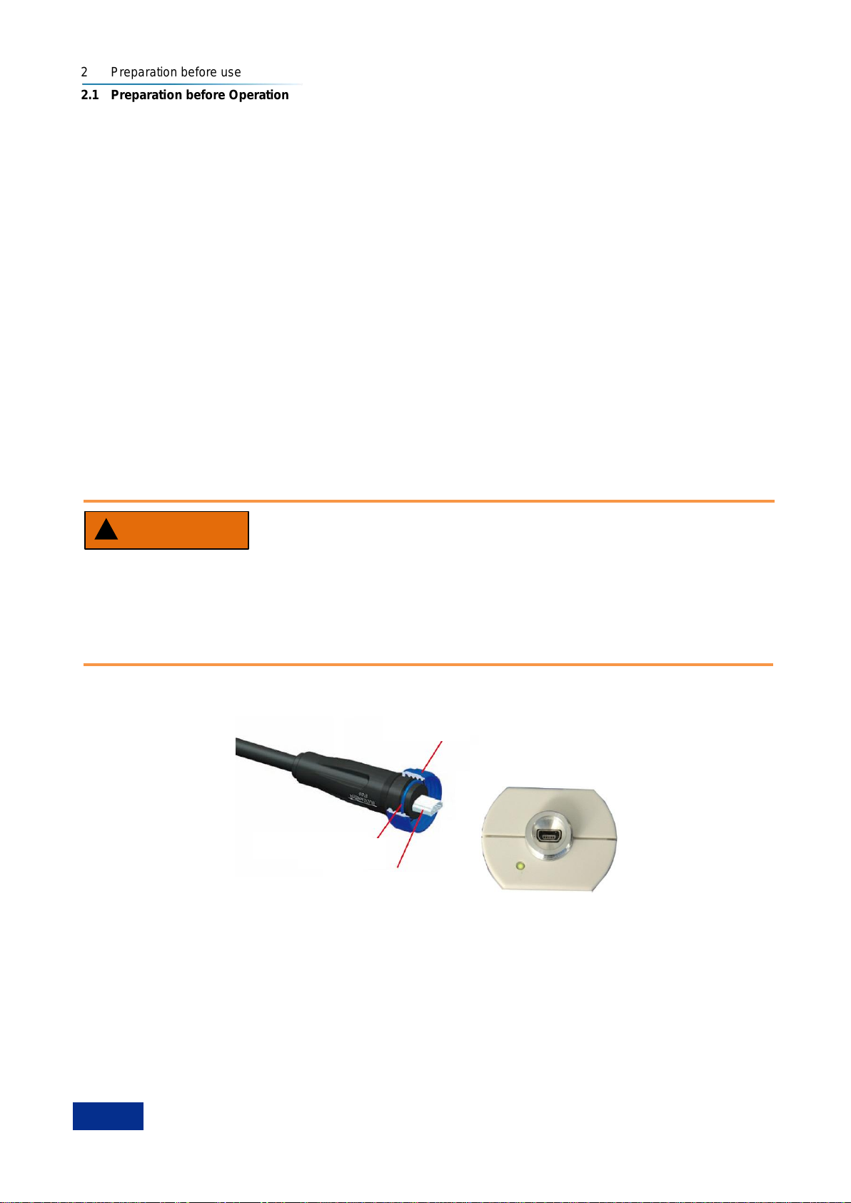
Step 2. As shown in Fig. 2.4, move both connectors straight together, so that they can be connected
smoothly; rotate the threaded sleeve of connector (rather than the connector itself) until it is tightened;
during connection, there can be no relative rotary motion both connectors;
Fig. 2.4 Connection
Step 3. As shown in Fig. 2.5, use a torque wrench to tighten the connectors and finish the connection;
the torque wrench shall not exceed the starting break point and an auxiliary wrench can be used to
prevent the connector rotating.
CAUTION
!
Keep it
unmoved
Rotate the
screw
2 Preparation before use
2.1 Preparation before Operation
9
Fig. 2.5 Completion of Final Connection with a Torque Wrench
3) Disconnection
Step 1. Support the connector to prevent any part from being shaken, distorted, or bent;
Step 2. Use an open-end wrench to prevent the main connector from rotating;
Step 3. Use another wrench to loosen the screw on the connector.
Step 4. Loosen the screw by hand until the connection is completely broken.
Step 5. Separate two connectors by pulling them apart in parallel.
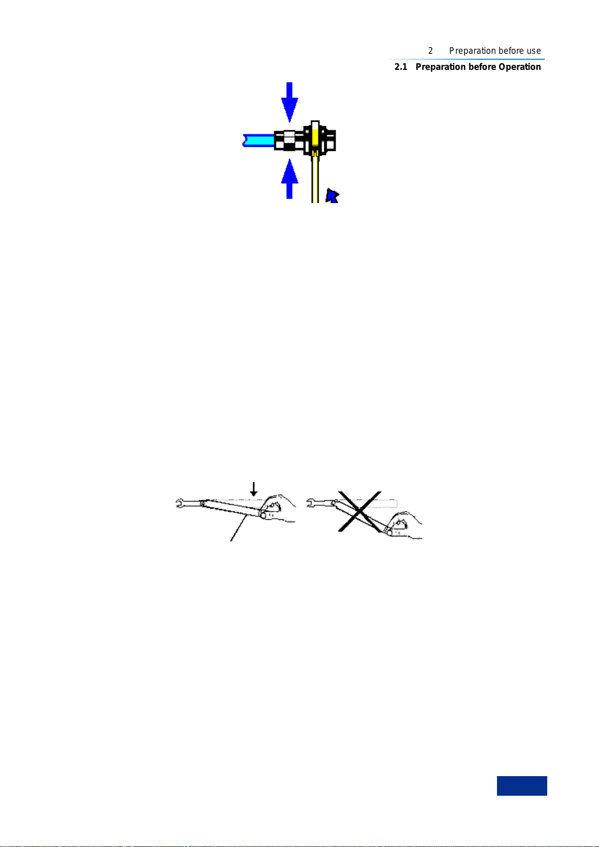
4) Use of the torque wrench
The torque wrench should be used as indicated in Figure 2.6. Please pay attention to the following points
when using the torque wrench:
Confirm that the torque of the torque wrench is set correctly before use;
Ensure that the angle between the torque wrench and the other wrench (used to support the
connector or cable) is less than 90obefore applying a force;
Gently grasp the end of the torque wrench handle and apply a force in the direction perpendicular to
the handle until the breakout torque of the wrench is reached.
Fig. 2.6 Use of Torque Wrench
5) Use and preservation of connectors
1) Protect the connectors with a protective sheath when not used;
2) Do not place the connectors, tools, etc. in a same box, which is the most common cause leading to
connector damage;
3) Keep the connector and analyzer at the same temperature. If the connector is held by hand or
cleaned with compressed air, the temperature will be significantly changed. The connector can be
used for calibration only after its temperature is stabilized;
4) Do not touch the joint surface of the connector because it is difficult to remove skin oil and dust
particles from the joint surface;
5) Do not place the contact surface of the connector downwards onto a hard surface; otherwise, the
electroplated layer and joint surface of the connector may be damaged.
Torque direction
Stop applying a force when the handle bends
Keep it
unmoved
2 Preparation before use
2.2 Routine Maintenance
10
6) Wear an anti-static wrist strap and work on a grounded conductive workbench mat to protect the
analyzer and connector against electrostatic discharge.
6) Cleaning of connectors
It is necessary to wear an anti-static wrist strap when cleaning the connectors as per the following steps:
1) Use clean low-pressure air to remove the loose particles on the thread and joint surface of the
connector and check the connectors thoroughly. If further cleaning is required, proceed as follows;
2) Wet (but not soak) a lint-free cotton swab with isopropyl alcohol;
3) Use a cotton swab to remove dirt and debris from the joint surface and thread of the connector.
When cleaning the inner surface, be careful not to apply an external force to the central inner
conductor or leave the cotton swab fibers on the central conductor of the connector;
4) Evaporate the alcohol and then blow the surface clean with compressed air;
5) Check the connectors to confirm that they are free of particles and residues;
6) If the connector still has visible defects after cleaning, it indicates that the connector may be
damaged. Never use a damaged connector, and confirm the causes of damage before
measurement and connection.
7) Use of adapter
When the measuring port of analyzer is different from the type of connector used, an adapter must be
adopted for measurement connection. In addition, even if the measurement port of the analyzer is the
same as the type of connector for the port of tested part, it is also a good idea to use an adapter. Under
these two conditions, the measuring port can be protected, thus extending its service life and reducing
the maintenance cost. Before connecting the adapter to the measuring port of analyzer, it should be
carefully checked and cleaned. A high-quality adapter should be used to reduce the impact of mismatch
on the measurement accuracy.
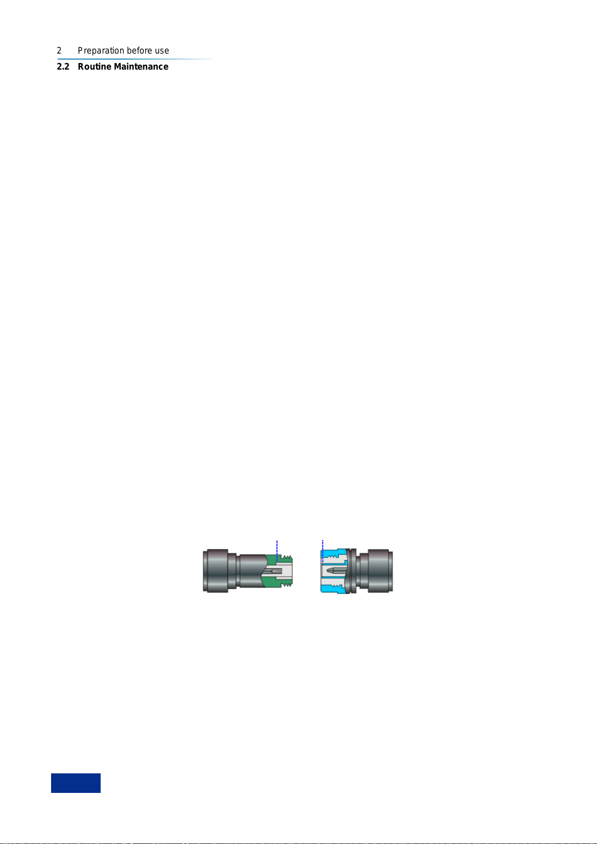
8) Joint surface of connector
An important concept in microwave measurement is the reference surface for all measurement. In the
case of calibration, the reference surface is defined as the surface on which the measuring port and the
calibration standard are jointed. Proper connection and calibration depend on whether the connectors
can be completely and straightly contact with each other at each point of the joint surface, so as to
ensure minimum power standing-wave ratio, achieve the minimum power loss, and ensure the
measurement accuracy.
Fig. 2.7 Calibration Surface
2.2 Routine Maintenance
This section introduces the daily maintenance method of the 87230 series USB CW power sensor.
2.2.1 Cleaning method
Clean the instrument surface as per the following steps:
Step 1. Power it off, and disconnect the power cord;
Step 2. Gently wipe off the surface with a piece of dry or slightly moist soft cloth, and it is not allowed to
Joint surface
N type (female)
N type (male)

2 Preparation before use
2.2 Routine Maintenance
11
wipe off its inside;
Step 3. Do not use chemical detergents, such as alcohol, acetone or diluted detergent.
2.2.2 Maintenance of testing port
The 87230 series USB CW power sensor has a USB cable connector and a microwave power signal
input port. If the connector is damaged or there is dust inside, the RF wave band test results will be
affected; therefore, please observe the following methods for maintenance of such connector:
Connectors shall be kept clean and away from dust;
To prevent ESD, do not directly contact the connector surface;
Do not use damaged connector;
Clean connectors with a dryer, and do not grind the surface with a tool like abrasive paper.
3 Typical Applications
3.1 Selection of Power Sensor
12
3 Typical Applications
This chapter introduces the selection of the 87230 series USB CW power sensor, and detailed operation
methods and measurement procedures for different measurement functions.
Model selection of power sensor……………………………………………………………………….... 12
Virtual Power Measurement Panel…………………………………………………………………........ 12
Zeroing and Calibration Before Measurement……………………………………………………………14
CW Power Measurement…………………………………………………………………....................... 15
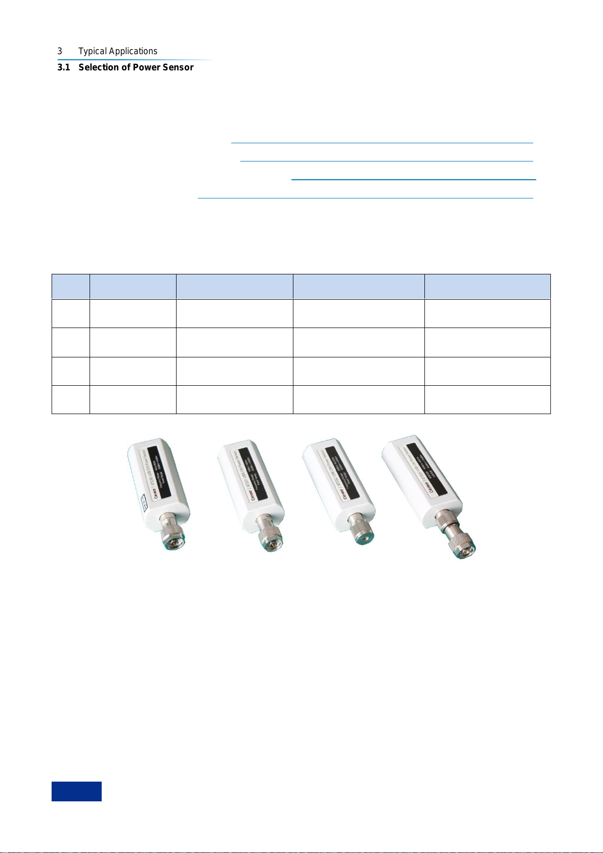
3.1 Selection of Power Sensor
The 87230 series USB CW power sensor includes four models including 87230, 87231, 87232 and
87233, as shown in the following Table.
Table 3.1 87230 Series USB CW Power Sensor
No.
Sensor Model
Power Range
Frequency range
Interface Type
1
87230
-50 dBm ~ +20 dBm
9 kHz ~ 6 GHz
N(m)
2
87231
-60 dBm ~ +20 dBm
10 MHz ~ 18 GHz
N(m)
3
87232
-60 dBm ~ +20 dBm
50MHz to 26.5GHz
3.5 mm (m)
4
87233
-60 dBm ~ +20 dBm
50MHz to 40GHz
2.4mm (m)
Fig. 3.1 87230 Series USB CW Power Sensor
The 87230 series USB CW power sensor can realize continuous wave power measurement. As the
performance specifications are different by model, the user can select the suitable sensor according to
the characteristics and measurement requirements of signals to be tested as well as the specifications of
each sensor. The basic functions of the sensor are shown in Table 3.1. Please refer to “7.3 Technical
Specifications” of the User Manual for detailed description of specifications of each sensor.
3.2 Virtual Power Measurement Panel
The USB interface of the 87230 series USB CW power sensor conforms to the USBTMC (USB Test and
Measurement) protocol, which is a kind of enumerated equipment (namely, it can be found through the
viFindRsrc function of the VISA library). The vendor ID and equipment ID (decimal) are 1204 and 4100
respectively, and the serial number are as shown in each sensor.
The user can realize the remote control of the USB sensor through the VISA library; for the specific
configuration, please refer to the Programming Manual of the 87230 Series USB CW Power Sensor, and
the virtual power test panel can also be used for the power test. The user shall install the version above

3 Typical Applications
3.2 Virtual Power Measurement Panel
13
VISA3.0 and run the virtual power test panel program provided in CD. The open virtual power test panel
is as shown in Fig. 3.2.
Fig. 3.2 Virtual Power Test Panel
Connection and operation steps of the USB CW power sensor:
Step 1. Connect the USB power sensor with the computer; open the power test panel; select the USB
device to be connected in the pop up “Instrument Connection” window in the system, and click
“Connection” button. As shown in Fig. 3.3, the measurement process is normal;
Step 2. The user can check the type, serial number and firmware version number of the USB CW
power sensor in the “System”label on the left side of the window;
Step 3. Click or button of the toolbar, and the system will display the measurement
result in the open value window or disable measurement;
Step 4. The user can set the measurement efficiency, average number of times, range selection, etc.
in the “Channel” label window;
This manual suits for next models
4
Table of contents
Popular Accessories manuals by other brands


TOPPOINT
TOPPOINT LT91130 user manual

LEGRAND
LEGRAND Wattstopper LMPC-600 quick start guide

Richelieu
Richelieu DS63202P2A1C90 user manual

EMX Industries
EMX Industries IRB-MON instruction manual

NXP Semiconductors
NXP Semiconductors UM11227 user manual

Gordon AirPlay
Gordon AirPlay AirRingLarge owner's manual

System Sensor
System Sensor 52051E-RF Installation and maintenance instructions

Vega
Vega B-LIFT 8120 200 Evo Series manual

IFM Electronic
IFM Electronic efector 300 SU9001 operating instructions

Young Living
Young Living Desert Mist Operation manual

echoflex
echoflex TAP-31 installation guide

Sunbeam
Sunbeam TR6300 Instruction booklet