Seiko V182A Installer manual

1
Cal. V182A
PARTS CATALOGUE /TECHNICAL GUIDE
(x 1.0)
Movement
Item
[SPECIFICATIONS]
Cal. No. V182A
ø20.0 mm
19.0 mm between 3 o'clock and 9 o'clock sides
Outside diameter
ø19.4 mm
18.7 mm between 3 o'clock and 9 o'clock sides
Casing diameter
Height
•Solar power system
•Overcharge prevention function
•Energy depletion forewarning function
•Quick-start function
•Electronic circuit reset switch
•Train wheel setting device
•Date calendar
•Instant setting device for date calendar
Time indication
Driving system
Additional mechanism
0.45 ~ 2.20 V
From full charge to stoppage: Approx. 2 months
Loss/gain
Regulation system
Measuring gate by quartz tester
Solar power system
Titanium-lithium ion rechargeable battery
Power supply
Operating voltage range
Expected life per charge
Jewels 2 jewels
3 hands
Step motor (Load compensated driving pulse type)
Monthly rate at normal temperature range: less than 20 seconds
Nil
Rechargeable battery
Power generator
Use 10-second gate.
Movement size
2.4 mm (Including the battery portion)

2
PARTS CATALOGUE Cal. V182A
➡➡Please see the remarks on the following pages.
Disassembling procedures Figs. : 1 →40
Reassembling procedures Figs. : 40 →1
Lubricating: Types of oil Oil quantity
Moebius A Normal quantity
Silicone oil 500,000 c.s.
0022 247
•Battery lead terminal screw (1 pc.)
•Circuit block cover screw (3 pcs.)
8 Hour, minute and
second hands
9 Dial
1 Case back
2 Case back gasket
3 Case ring
4 4281 880
Contact point spring
6 Movement
7 Dial ring
5 Winding stem
10 Solar cell unit
11 Holding ring for dial
12 4246 514
Solar cell lead
terminal
13 0808 891
Date dial guard
14 Date dial
15 0810 890
Date jumper
16 0271 948
Hour wheel
17 0802 891
Date driving wheel

3
➡➡Please see the remarks on the following pages.
PARTS CATALOGUE Cal. V182A
32 4239 908
Rotor stator
31 4002 907
Coil block
33 0383 891
Setting lever
37 0806 890
Date corrector wheel
36 0282 890
Clutch wheel
35 Winding stem
34 0384 890
Yoke
39 4268 656
Battery connection (+)
38 0221 934
Center wheel and pinion
40 0100 968
Main plate
18 0022 247
Battery lead terminal screw
19 3027 29Y
Rechargeable battery unit
20 0022 247
Circuit block cover screw
21 4457 903
Circuit block cover
22 4000 656
Circuit block
23 0125 907
Train wheel bridge
24 0241 934
Fourth wheel and pinion
25 0231 904
Third wheel and pinion
26 0701 904
Fifth wheel and pinion
27 4146 907
Step rotor
28 0261 904
Minute wheel
29 0281 904
Setting wheel
30 0391 890
Train wheel setting lever

4
PARTS CATALOGUE Cal. V182A
Remarks:
10 Solar cell unit 4020 573
The type of solar cell unit is determined based on the design of cases. Check the case number and refer to
“Casing Parts Catalogue” to choose a corresponding solar cell unit.
11 Holding ring for dial 0866 775
The type of holding ring for dial is determined based on the design of cases. Check the case number and refer
to “Casing Parts Catalogue” to choose a corresponding holding ring for dial.
14 Date dial
0878 882 3 o’clock Black White
Part code Position of crown
and
calendar frame Color of figure Color of background
0878 883 3 o’clock Gold Black
The type of date dial is determined based on the design of cases. Check the case number and refer to “Casing
Parts Catalogue” to choose a corresponding date dial.
35 Winding stem 0351 860
The type of winding stem is determined based on the design of cases. Check the case number and refer
to “Casing Parts Catalogue” to choose a corresponding winding stem.

5
TECHNICAL GUIDE Cal. V182A
•The explanation here is only for the particular points of Cal. V182A.
•For the repairing, checking and measuring procedures, refer to the “TECHNICAL GUIDE, GENERAL
INSTRUCTIONS”.
I. STRUCTURE OF THE CIRCUIT BLOCK
4 Contact point spring
•How to install
Set the spring portion of the contact point spring to the winding
stem as shown in the illustration at right.
II. REMARKS ON DISASSEMBLING AND REASSEMBLING
Crystal unit
C-MOS-IC Solar cell input terminal (+)
Input terminal (–)
Solar cell input terminal (–)
Coil output terminal
Input terminal (+)
Contact point spring
Dial
Hooking portion
9 Dial
10 Solar cell unit
The dial and solar cell unit are fixed to the holding ring for dial
using four hooking portions of the ring.
•How to remove
1) Insert the tip of a screwdriver into a gap between the dial and
solar cell unit near a hooking portion, and then, pry up the
dial to release it from the hooking portion. Follow the same
procedure to release all the four hooked portions of the dial.
Notes: • Before removing the winding stem, be sure to remove
the contact point spring.
• Before installing the contact point spring, be sure to
install the winding stem.

6
TECHNICAL GUIDE Cal. V182A
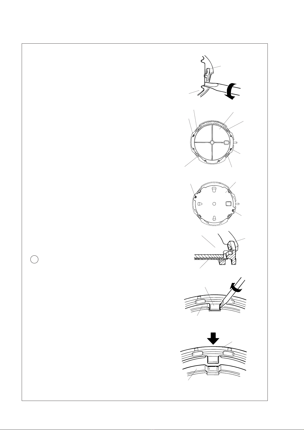
2) Insert the tip of a screwdriver into a gap between the solar cell
unit and holding ring for dial near a hooking portion, and then,
pry up the solar cell unit to release it from the hooking portion.
Follow the same procedure to release all the four hooked
portions of the solar cell unit.
Note: When removing the dial and solar cell unit, take care
not to damage or deform them.
•How to install
1) Set the notched portions of the solar cell unit to the guide posts
at the 4 o’clock and 10 o’clock sides of the holding ring for dial.
Note: At this step it is not necessary to hook the solar cell unit
to the four hooking portions of the holding ring for
dial.
2) Set the notched portions of the dial to the guide posts at the 4
o’clock and 10 o’clock sides of the holding ring for dial.
3) Push the circumference of the dial near the hooking portion to
set the dial and the solar cell unit to the four hooking portions
as shown in the illustration at right.
Notes: • When installing the dial, take care not to damage or
deform it.
• After installing the solar cell unit and dial, check that
they are fixed securely to the holding ring for dial by
the four hooking portions.
Hooking portion
Solar cell unit
Hooking portion
Guide post
at the 10
o’clock side
Guide post
at the 4
o’clock side
Hooking portion
Hooking portion Solar cell unit
Dial
Guide post
at the 10
o’clock side
Hooking portion
Guide post at
the 4 o’clock
side
11 Holding ring for dial
•How to remove
The holding ring for dial is fixed by two hooking portions at the 12
o’clock and 6 o’clock sides.
1) Insert the tip of a screwdriver into a gap between the hooking
portion and main plate as shown in the illustration at right, and
then, turn the screwdriver in the direction of the arrow to
release the hooking portion from the main plate.
•How to install
1) Set the hooking portions at the 12 o’clock and 6 o’clock sides
to the main plate.
2) Gently push the holding ring for dial at the hooking portions so
that they catch the main plate securely.
Dial Hooking portion
Solar cell unit
Hooking portion
Main plate
Push
Holding ring for dial
Main plate

7
TECHNICAL GUIDE Cal. V182A
Unlike conventional movements, the date dial guard is not fixed with screws. It is set to the main plate with
three protrusions, which are caught under the main plate by turning the guard. Then, it is fixed by two guide
pins.
•How to remove
1) Lightly lift the “A” portion of the date dial guard with
tweezers to release it from the guide pin, and then move
it counterclockwise until it mounts on the guide pin.
2) Release the “B” portion of the date dial guard in the
same way as described above, and then move it
counterclockwise until it mounts on the guide pin.
3) Check that all the three protrusions of the date dial guard
have come off from the main plate, and then remove the
date dial guard.
13 Date dial guard
“B” portion
Protrusion
Date dial guard
•How to install
1) Put the date dial guard on the main plate so that the “A”
and “B” portions are over the guide pins, as shown in
the illustrations at right.
2) Move the protrusion “D” of the date dial guard clockwise
so that it is caught under the main plate.
3) Slightly move the protrusions “C” and “E” clockwise
alternately to set them under the main plate.
Then, set the “A” and “B” portions of the date dial guard
to the guide pins.
4) Check that the date dial guard is fixed securely to the
main plate.
Protrusion “E”
“A” portion
Protrusion “C”
“A” portion
Guide pin
Tweezers
Protrusion “D”
“B” portion

8
TECHNICAL GUIDE Cal. V182A
19 Rechargeable battery unit
•How to remove
Remove the battery lead terminal screw, and then pry up
the “A” portion in the illustration with tweezers to remove
the rechargeable battery unit.
•How to install
Set the “B” portion of the battery lead terminal to the guide
hole of the main plate, and then push the center portion of
the rechargeable battery unit (the “C” portion in the
illustration) to fix it in position.
Battery lead terminal
Notes: •Be sure to observe the correct polarity of the
rechargeable battery unit. The (–) side has the
lead terminal.
•Handle the rechargeable battery unit with care
so as not to short-circuit its (+) and (–) terminals.
“A” portion
“C” portion
Rechargeable battery unit
23 Train wheel bridge
Refer to the illustrations below to check where to install the respective wheels.
Step rotor
Third wheel and pinion
Step rotor
Fourth wheel and pinion
Fifth wheel and pinion Third wheel and pinion
Minute wheel
Setting wheel
•Setting position
Refer to the illustration at right.
•Setting position
Center wheel and pinion
21 Circuit block cover
•How to install
Have the three hooking portions of the circuit block cover
catch the main plate securely.
30 Train wheel setting lever
33 Setting lever
34 Yoke
35 Winding stem
•The date corrector wheel has some elasticity in the
contact with the winding stem so that they can move
together.
• Push in the winding stem straight toward the center of
the main plate.
“B” portion
Setting wheel
Fifth wheel and pinion
Fourth wheel and pinion
Minute wheel
Train wheel setting lever
Yoke
Setting lever
Winding stem
Date corrector wheel

9
TECHNICAL GUIDE Cal. V182A
III. VALUE CHECKING
•Coil block resistance
1.8KΩ~ 2.2KΩ
•Current consumption
For the whole movement : Less than 0.8µA (with voltage supplied from a battery)
For the circuit block alone : Less than 0.4µA (with voltage supplied from a battery)
<Measuring the current consumption for the whole movement>
1) Remove the solar cell unit and rechargeable battery.
2) Connect the tester as shown in the illustration.
3) Start the measurement 30 seconds to 2 minutes after connecting the tester, checking that a stable
measurement is obtained.
S-850
Input pattern (–)
Battery connection (+)
MA-40A

10
TECHNICAL GUIDE Cal. V182A
<Measuring the current consumption for the circuit block alone>
• Connect the tester to the input terminals (+) and (–) of the circuit block, and wait for 30 seconds to 2
minutes before starting the measurement, checking that a stable measurement is obtained.
Remarks: When the current consumption exceeds the standard value for the whole movement but is within
the standard value range for the circuit block alone, the watch is generating a driving pulse to
compensate for the heavy load that may be applied to the gear train, etc.
In this case, overhaul and clean the movement parts and then measure current consumption for
the whole movement again.
•Output voltage for the solar cell unit
<Measuring the output voltage for the watch>
1) Set the dial to the solar cell unit.
2) Make sure that the rechargeable battery unit is not installed into the watch.
3) Pull out the crown to the second click and reset the circuit.
4) Connect the tester as shown in the illustration.
Pull out the crown to the
second click.
5) Place the watch at a distance of 5cm under a fluorescent light of 15 to 20 watts, exposing the dial side to
the light, and then measure the output voltage.
•Use either of the following two methods to measure the output voltage for the solar cell unit.
1. Measurement of the output voltage for the watch
2. Measurement of the output voltage for the solar cell unit alone
Remarks: If the output voltage for the watch is less than the specified value, measure the output voltage for
the solar cell unit alone.
If the output voltage for the solar cell unit alone exceeds the specified value, check the solar cell
lead terminal for conductivity, etc.
Output voltage when the watch is placed at a distance of 5cm
under a fluorescent light of 15 to 20 watts: More than 2.3V.
5cm
Fluorescent light
(15 to 20W)

11
TECHNICAL GUIDE Cal. V182A
1) Connect the tester to the output terminal of the solar cell unit as shown in the illustration.
2) Place the solar cell unit at a distance of 5 cm under a fluorescent light of 15 to 20 watts, exposing the
solar cell side to the light, and then measure the output voltage.
<Measuring the output voltage for the solar cell unit alone>
The quick-start function can be checked only when the rechargeable battery voltage is less than 0.9V.
Before checking the function, therefore, be sure to measure the voltage.
(Refer to step 1 in “• Checking the recharging function”.)
•Checking the quick-start function
<Checking procedure>
• After checking that the watch stops operating, place
the watch at a distance of 50cm under a fluorescent
light of 15 to 20 watts, exposing the dial side to the
light. Then, check if the second hand starts moving
at 2-second intervals within 10 seconds.
Fluorescent light
(15 to 20W)
Solar cell unit
5cm
Fluorescent light
(15 to 20W)
50 cm

12
TECHNICAL GUIDE Cal. V182A
•Checking the recharging function
A conventional method of checking the recharging function is to check the difference of the rechargeable
battery voltage between before and after a recharge.
<Checking procedure>
1) Apply the probes of the tester as shown in the illustration to measure the voltage of the rechargeable
battery before recharge.
2) Place the watch at a distance of 5cm under a fluorescent light of 15 to 20 watts, and charge it for 30 minutes.
Remarks:
• Be sure to use a fluorescent light to charge the watch, as light
sources generating heat may cause damage to the watch. To
charge the watch efficiently, place it under the center of the
fluorescent tube.
• While charging the watch, make sure that the watch
temperature does not exceed 50°C.
3) After recharging for 30 minutes, apply the probes of the
tester in the same manner as in step 1) above, and
measure the rechargeable battery voltage while keeping
the watch exposed to the light.
4) Refer to the table below to determine whether the recharging function is normal or not.
Voltage before recharge Criteria for recharging quality
1.01 ~ 1.30V The battery is normal if the rechargeable battery voltage has
increased more than 0.04V after recharge.
[Guideline for the quality of the recharging function]
* The above criteria are applicable only when the rechargeable battery voltage before recharge is within
the range of 0.5V and 1.3V.
0.5 ~ 1.00V The battery is normal if the rechargeable battery voltage
obtained after recharge is more than 1.2V.
Fluorescent light
(15 to 20W)
5cm
Fluorescent light
(15 to 20W)
5cm

13
97-6 Printed in Japan
TECHNICAL GUIDE Cal. V182A
•Remarks on measuring the time accuracy
•Before measuring the time accuracy, install the dial.
•If a stable measurement cannot be obtained, place
the watch on the microphone of the quartz tester and
leave it untouched for more than 5 minutes.
Then, measure the accuracy again.
Microphone of the
quartz tester
Illumina-
tion
(lux)
Light source Environment Time required
for full charge
Time required
for 1-second
intervals *
Time required
to maintain
one-day usage
500
700
1,000
3,000
5,000
10,000
10,000
100,000
60-watt incandescent
light
Fluorescent light
30-watt fluorescent
light
30-watt fluorescent
light
30-watt fluorescent
light
30-watt fluorescent
light
Sun
Sun
Distance of 60 cm
Office, overhead
Distance of 70 cm
Distance of 20 cm
Distance of 12 cm
Distance of 3 cm
Cloudy weather
Fair weather
110 hours
82 hours
60 hours
20 hours
10 hours
5 hours
5 hours
2.1 hours
8 hours
6 hours
4 hours
1.3 hours
33 minutes
15 minutes
15 minutes
7 minutes
100 minutes
75 minutes
55 minutes
18 minutes
9 minutes
5 minutes
5 minutes
2 minutes
[Caution for charging]
• To prevent damage to the watch caused by heat from a light source, make sure that the watch
temperature does not exceed 50°C while charging the watch.
• The above table provides only a general guideline, and the actual charging time may differ from model
to model.
* The values in this column represent the charging times required until the second hand moves
constantly at 1-second intervals after the watch starts operating with the second hand moving at 2-
second intervals. Even if the watch is not charged for the time specified in the column, the second hand
may temporarily move at 1-second intervals. But, it will soon resume moving at 2-second intervals.
Therefore, be sure to charge the watch for more than the specified period.
•Guideline of charging time
Table of contents
Other Seiko Accessories manuals
Popular Accessories manuals by other brands

Dragino
Dragino LHT65 user manual

PCB Piezotronics
PCB Piezotronics IMI SENSORS HT640B71 Installation and operating manual

UBTECH
UBTECH RAD001 user manual

COMPULOAD
COMPULOAD CL2000MKII Installation, Calibration & Operation Manual

Synetica
Synetica enLink Status-VC user guide

bitmore
bitmore e-Pro Power 10K user manual