Ceyear 6419 User manual
6419 Distributed Optical Fiber Strain Tester
User Manual
China Electronics Technology Instruments Co., Ltd

January 2018

Foreword
Thank you very much for choosing and using the 6419 distributed optical fiber strain tester produced by China
Electronics Instrument Co., Ltd. The company produces high-grade, high-precision and advanced products, with
the highest quality cost-effectiveness among similar products. We always comply with the ISO9000 standard
during the production process, and we’re customer-oriented and consider the quality as the enterprise's life. Please
read this manual carefully for your convenience. We will make our best efforts to meet your needs, provide you
with the most cost-effective control equipment, and bring you first-class after-sales service. With the consistent
purpose of "good quality, considerate service", it’s our commitment to provide satisfactory products and services
to you. We sincerely hope to bring convenience and speed to your work, and welcome your inquiries through calls:
Website: www.ceyear.com
E-mail: sales@ceyear.com
Address: No. 98, Xiangjiang Road, Qingdao City, China
Postal code: 266555
This manual describes the purpose, performance characteristics, basic principles, application methods,
maintenance, and precautions of the 6419 distributed optical fiber strain tester to help you become familiar with
and master the operating methods and key points of the controller. In order to make better use of this product and
create more economic benefits for you, please read this manual carefully.
Due to the tight time and the limited capability of the author, it is inevitable that there are errors and omissions in
this manual, please criticize and correct! We apologize for the inconvenience caused by the mistakes we made.
Statement:
This manual is the third edition of the user manual of 6419 distributed optical fiber
strain tester, the version number is D.2.
The contents of this manual are subject to change without notice. The right of
interpretation to the contents and the terms used in the manual belongs to China
Electronics Technology Instruments Co., Ltd.
The copyright of this manual belongs to China Electronics Technology Instruments
Co., Ltd. Any unit or individual may not modify or tamper with the contents of this
manual without the authorization of China Electronics Technology Instruments Co.,
Ltd, and may not copy or distribute this manual for the purpose of profit. China
Electronics Technology Instruments Co., Ltd reserves the right to pursue legal
liability for any violation.

ii
Table of Contents
Safety requirements....................................................................................................................................................1
Safety terms used in this manual................................................................................................................................1
Warnings for the use of instrument.............................................................................................................................2
Notes for the use of instrument...................................................................................................................................3
Maintenance and service.............................................................................................................................................3
Calibration requirements ............................................................................................................................................4
Warranty and repair of instrument..............................................................................................................................4
Chapter I Overview ....................................................................................................................................................5
1 Overview ofinstrument....................................................................................................................................5
2 Components of instrument...............................................................................................................................6
2.1 Basic components.................................................................................................................................6
2.2 Optional components............................................................................................................................6
3. Description of instrument panel......................................................................................................................6
3.1 Viewof instrument front panel..............................................................................................................6
3.2 Viewof instrument back panel..............................................................................................................8
Chapter II Description of Operation Interface..........................................................................................................10
1 Main operation interface................................................................................................................................10
1.1 Test result area....................................................................................................................................10
1.2 Test condition area..............................................................................................................................10
1.3 Waveform operation area ...................................................................................................................10
1.4 Sub-waveform window ......................................................................................................................11
1.5 Function menu area............................................................................................................................11
1.6 Window display area..........................................................................................................................11
2 Structure and function of main menu ............................................................................................................11
Chapter III Description of Test Conditions...............................................................................................................15
1 Description of test condition sub-menu.........................................................................................................15
2 Description of test condition parameters.......................................................................................................15
2.1 Range..................................................................................................................................................15
2.2 Pulse width.........................................................................................................................................16
2.3Average times.....................................................................................................................................16
2.4 Resolution ..........................................................................................................................................17
2.5 Refractive index.................................................................................................................................18
2.6 Starting point......................................................................................................................................18
2.7 Output optical power..........................................................................................................................19
2.8 Start frequency...................................................................................................................................19
2.9 Ending frequency...............................................................................................................................20
2.10 Frequency interval............................................................................................................................21
2.11 fB (0)................................................................................................................................................21
2.12 CS.....................................................................................................................................................22

iii
2.13 Continuous test.................................................................................................................................23
2.14 Time interval ....................................................................................................................................23
2.15Autosave...........................................................................................................................................24
2.16 File serial number.............................................................................................................................24
2.17 File type............................................................................................................................................24
2.18Autosave path...................................................................................................................................24
3 Description on operation of test condition interface......................................................................................25
3.1 Description of operation of input box ................................................................................................25
3.2 Description of operation of drop-down box.......................................................................................25
Chapter IV Description of Window Display.............................................................................................................27
1. Description of the state of window display area...........................................................................................27
1.1 Multiwindow state..............................................................................................................................27
1.2 Strain distribution window.................................................................................................................29
1.3 Spectral width distribution window ...................................................................................................34
1.4 Brillouin Spectrum Display dialog box..............................................................................................36
1.5 Loss distribution window...................................................................................................................39
1.6 Comprehensive loss window..............................................................................................................41
2 Description of sub-waveform window ..........................................................................................................44
Chapter V Description of 3D Display Functions......................................................................................................46
1 Overview of state...........................................................................................................................................46
2 Description of display sub-menu...................................................................................................................46
3 Description of display operation....................................................................................................................46
Chapter VI Description of File Functions.................................................................................................................48
1 File opening...................................................................................................................................................48
2 File saving .....................................................................................................................................................49
3 Open reference...............................................................................................................................................49
4 Description of file type..................................................................................................................................50
4.1 sta file format .....................................................................................................................................50
4.2 eis file format .....................................................................................................................................50
Chapter VII Description of System Menu................................................................................................................52
1 Description of system sub-menu ...................................................................................................................52
2 Description of VFL functions........................................................................................................................52
3 Description of system self-check functions...................................................................................................53
4 Description of system settings sub-menu ......................................................................................................53
5 Help...............................................................................................................................................................54
Chapter VIII Application Methods...........................................................................................................................56
1 Basic operation..............................................................................................................................................56
1.1 Turn on the instrument .......................................................................................................................56
1.2 Fiber access........................................................................................................................................56
1.3 Setting parameters..............................................................................................................................57

iv
1.4 Turn off the instrument.......................................................................................................................57
2 Test operation.................................................................................................................................................58
2.1 Strain distribution test of fiber............................................................................................................58
2.2 Loss distribution test of fiber..............................................................................................................59
2.3 Brillouin spectrum test of fiber ..........................................................................................................60
2.4 Brillouin spectral width test ...............................................................................................................60
2.5 Fiber length test..................................................................................................................................61
2.6 Continuous test of fiber strain............................................................................................................62
3 Visible red light fault location (VFL) function..............................................................................................63
4 File management............................................................................................................................................63
4.1 Open the data file...............................................................................................................................64
4.2 Save the data files...............................................................................................................................64
4.3 Delete the data files............................................................................................................................64
4.4 Open the reference files......................................................................................................................65
5 Waveform comparison function.....................................................................................................................66
6 Remote control function................................................................................................................................67
Chapter IX General Faults and Processing Methods................................................................................................68
1 Quick check of general fault..........................................................................................................................68
2 Setting of refractive index .............................................................................................................................69
3 Solutions when the frequency setting range deviates from the initial frequency shift to a large extent........69
4 Adjustment of optical power..........................................................................................................................72
5 Relationship among common pulse width, resolution and length measurement...........................................72
6 Brightness adjustment....................................................................................................................................73
7 Calibration of touch screen............................................................................................................................73
Chapter X Working Principles..................................................................................................................................74
1 Fiber optic sensing technology......................................................................................................................74
2 Distributed optical fiber sensing technology.................................................................................................74
3 Spontaneous Brillouin scattering...................................................................................................................74
4 BOTDR technology.......................................................................................................................................75
Chapter XI Technical Parameters .............................................................................................................................77
1 General characteristics...................................................................................................................................77
2 main functions ...............................................................................................................................................77
3 Main technical indicators...............................................................................................................................77
AppendixA Instruction for Use of the Analysis Software........................................................................................79
1 Software Installation......................................................................................................................................79
1.1Runtime Environment.........................................................................................................................79
1.2 Installation Procedures.......................................................................................................................79
1.3 Software Running...............................................................................................................................80
1.4 Software Uninstallation......................................................................................................................80
2 Software Interface..........................................................................................................................................81

v
3 Data Reading .................................................................................................................................................81
4 Data Display..................................................................................................................................................82
4.1 Display Mode.....................................................................................................................................82
4.2 Marker Placement ..............................................................................................................................82
4.3 Curve Information..............................................................................................................................83
4.4 Curve Zooming ..................................................................................................................................84
4.5 Cursor Operation................................................................................................................................84
4.6 Settings...............................................................................................................................................84
5 DataAnalysis.................................................................................................................................................85
6 Data Export and Print....................................................................................................................................87
6.1 Data Export ........................................................................................................................................87
6.2 Print....................................................................................................................................................88
7 Remote Control..............................................................................................................................................90
7.1 Connection Parameters.......................................................................................................................90
7.2 Remote Control..................................................................................................................................90
7.3 Disconnect..........................................................................................................................................91
8 Status Bar and QuickAccess Toolbar............................................................................................................91
8.1 Status Bar...........................................................................................................................................91
8.2 Quick Access Toolbar.........................................................................................................................91
Appendix B 6419 Remote Control Command Set....................................................................................................93
Appendix C 6419 Ordering Information ..................................................................................................................97
Appendix D Identification of FC/APC from FC/UPC and Jumper Connection.......................................................98
1 FC/APC and FC/UPC Optical Fiber Connector ............................................................................................98
2 Usage of FC/APC to FC/UPC Transfer Jumper ............................................................................................98
3 Usage of FC/APC-FC/APC Extension Jumper ............................................................... 错误!未定义书签。
Appendix E Maintenance and Cleaning of the Optical Output Port.......................................................................101
1 Maintenance of the Optical Output Port......................................................................................................101
2 Cleaning of the Optical Output Port............................................................................................................101
Appendix F Maintenance, Check, and Cleaning of the Fiber End Face.................................................................103
1 Introduction to the Structure of the Fiber End Face ....................................................................................103
2 Maintenance of the Fiber End Face.............................................................................................................103
3 Check of the Fiber End Face .......................................................................................................................103
4 Cleaning of the Fiber End Face ...................................................................................................................105
Appendix G Check and Handling of Optical Fiber Break......................................................................................107
1 Check of Optical Fiber Break......................................................................................................................107
1.1 Check of Optical Fiber Break with BOTDR....................................................................................107
1.2 Check of Optical Fiber Break and High-loss Point via VFL............................................................109
2 Handling of Optical Fiber Break .................................................................................................................110
Appendix H Recommended Tools for Cable Laying, Maintenance and Testing....................................................111

1
Safety requirements
The following general safety precautions must be taken at any stage of operating the instrument. Failure to take
these safety precautions or to follow the warnings and precautions described elsewhere in this manual will violate
the safety standards for the design, manufacture, and use of the instrument. China Electronics Technology
Instruments Co., Ltd assumes no responsibility for the consequences arising from users’violation of these
requirements.
Use environment
For the working environment and storage environment of this instrument, please refer to the description of the
technical parameters in Chapter XI.
Power supply
For the requirements of the working power of this instrument, please refer to the description of the technical
parameters in Chapter XI. The working power of this instrument must range from 198Vac to 242Vac. Be sure to
use the dedicated three-wire power cord shipped with the instrument or the three-wire power cord of the regular
manufacturer's specifications, and ensure that the grounding is good, so as to avoid inducting voltage generated by
the enclosure. The fuse of the same specification shall be used when replacing the fuse in the fuse holder.
Do not use the instrument in an explosive or flammable environment
Do not use the instrument in the presence of flammable gases or fumes.
Do not disassemble any parts of the instrument
Do not disassemble any parts of the instrument except those that are authorized to be replaced by the users.
Replacement of parts and internal adjustments can only be carried out by the maintenance personnel authorized by
or entrusted by China Electronics Technology Instruments Co., Ltd.
Safety terms used in this manual
: Remind users to pay attention to a process, operation method, or similar situation. Failure to
operate properly or in accordance with the rules may result in personal injury or damage to the
instrument.
: Remind users to pay attention to a process, operation method, or similar situation. Failure to
operate properly or in accordance with the rules may result in partial or whole damage to the
instrument.
: Information that aids in the use and maintenance of the instrument.
Warning!
Caution!
Note!

2
Warnings for the use of instrument
Requirements for power supply
: The power supply used in this instrument must meet the following requirements: 220VAC ±
10%, 1.5A, 50 ~ 60Hz. Using a power supply that is too high/low or unstable will cause damage
to the instrument. Using a power supply that is too high/low or unstable will cause damage to
the instrument.
Laser safety
The safety standards for the lasers used in this instrument are in accordance with IEC65 and IEC348.
Although the output intensity of the laser used in this instrument is within the safety standard, it
may damage the visual acuity, so the output of the laser should be prevented from directly
shooting into the eye. Do not look directly into the light output connector of the instrument with
your eyes, and do not look directly at the end of the fiber during testing. When the VFL function
of the instrument is turned on, do not look directly at the VFL's output port or the end of the
fiber connected to the VFL output port.
Use of distributed optical fiber strain tester (BOTDR)
(1) It is absolutely not allowed to connect an optical fiber with any optical signal to the test port
of the 6419 distributed optical fiber strain tester. This may result in inaccurate measurement
results and even permanent damage to the instrument. Please ensure that all fibers tested by this
instrument are in a no-signal state.
(2) It is absolutely not allowed to connect and disconnect the optical fiber during the test of the
6419 distributed optical fiber strain tester. This will cause the instantaneous increase of echo of
the optical fiber tested by the instrument, which may cause permanent damage to the instrument.
(3) It is absolutely not allowed to connect the fiber interface that does not match the optical
interface of the 6419 distributed optical fiber strain tester to the test port of the 6419 distributed
optical fiber strain tester. This will not only increase the insertion loss due to the mismatched
optical interface and result in no inaccurate test results, but will also cause permanent damage to
the optical interface.
Transportation and packaging
(1) Please pack the 6419 distributed optical fiber strain tester with the original standard
aluminum alloy box during transportation, and ensure that the 6419 distributed optical fiber
strain tester does not move in the aluminum alloy box. Special note: When placing the
instrument in an aluminum alloy box, no filler is allowed in front of the LCD display to
avoid damage to the LCD display during transportation.
(2) Care should be taken during transportation to avoid damage to the 6419 distributed optical
fiber strain tester caused by severe shock and vibration.
Warning!
Warning!
Warning!
Warning!

3
Notes for the use of instrument
LCD display
(1) Do not use a sharp object to click on the LCD screen, and do not impact the LCD screen
with big power. This will damage the LCD screen.
(2) Do not drop or splash organic solvents or contaminants on the LCD screen, such as acetone,
oil, antifreeze, grease, etc., otherwise the LCD screen will not work properly.
(3) Wipe the LCD screen with silk cloth or soft fabric. Do not wipe the LCD screen with organic
solvent, otherwise, this may damage the LCD screen.
Use of distributed optical fiber strain tester (BOTDR)
(1) The light output connector of the instrument has a delicate and fragile ceramic positioning
core inside. When the fiber is connected, be sure to insert the fiber plug in parallel and screw it
tightly after aligning the positioning pin.
(2) When using this instrument for measurement, the inside of the light output connector of the
instrument and the end face of the light output connector of the instrument must be kept clean to
prevent the grease and other contaminants from contaminating the light output connector.
Otherwise, it will cause measurement error of the instrument, and may cause the instrument not
be able to test the fiber.
(3) If possible, when testing the instrument, point the end of the fiber under test to a non-
reflective object.
Maintenance and service
(1) Please use the original packaging materials when carrying the instrument to avoid severe
shock and vibration.
(2) The instrument should be stored under the ambient temperature range between 0°C and 50°C,
and it should be kept ventilated and dried without direct sunlight.
(3) When storing the instrument, the dust cover on each optical port of the instrument should be
covered.
Caution!
Caution!
Note!

4
Calibration requirements
The validity of the technical parameters is related to the operating environment of the instrument. The duration of
the calibration can be extended or shortened depending on the use intensity, the operating environment and the
maintenance of the instrument. You should determine the appropriate calibration period based on your needs.
In the case of normal use of the instrument, it is recommended that the 6419 distributed optical fiber strain tester
be calibrated once a year. For details, please call the service number.
Warranty and repair of instrument
(1) The warranty period of the whole machine (except for the light output connector and
consumables) is 18 months. Items offered during product promotions are not within the scope of
the warranty.
(2) The light output connector and optical fiber output contact of the instrument are consumables,
which are not within the scope of the warranty.
(3) Damage or deterioration of the instrument due to irresistible force and human factors is
within the scope of the warranty.
(4) The instrument shall be maintained by China Electronics Technology Instruments Co., Ltd or
its designated authorized maintenance unit. It is illegal for any other unit or individual to
disassemble and repair the instrument. The instrument will lose its warranty qualification and
the China Electronics Technology Instruments Co., Ltd reserves the right to pursue legal
liability for violators.
(5) The instrument will lose its warranty qualification once it is dismantled and disassembled in
an unauthorized manner. The instrument will lose its warranty qualification once the fastening
screws or sealing strip is removed.
Description:
China Electronics Technology Instruments Co., Ltd reserves the right to make any changes to the design and
structure of the 6419 distributed optical fiber strain tester at any time, but has no obligation or responsibility to
freely modify or replace the products sold for free. Accessories of this product, including but not limited to fiber
end face tester, optical fiber patch cords and mice, are not subject to the warranty of this manual.
When the instrument needs to be returned for repaired, calibration or maintenance, the following
points shall be noted:
(1) If the test data is stored in the instrument, please back up the data to avoid loss.
(2) Please use the original packaging box for packaging and transportation.
(3) If other packaging box is used, please make sure there is at least soft filler of 3 cm around
the instrument.
(4) To reduce the impact of external forces.
(5) Please indicate the contact address, contact number, description of the situation, etc. when
the instrument is returned.
(6) Please seal the packaging box with tape before shipping.
(7) Damage caused by improper packaging is not within the scope of the warranty when the
instrument is returned.
Caution!
Note!

Chapter I Overview
5
Chapter I Overview
1 Overview of instrument
The 6419 distributed optical fiber strain tester (hereinafter referred to as 6419 BOTDR can test the strain
distribution, loss distribution and Brillouin scattering spectrum of fiber optic cable simultaneously. It can
simultaneously display the 3D and multiple distribution parameters, and has the advantages of high strain test
accuracy, good repeatability and single-ended non-destructive testing, which is an indispensable test instrument in
the field of Optical Fiber Communications and Optical Fiber Sensing.
The product can be widely used in the development, production and testing, construction and acceptance of fiber
optic gyro, fiber optic hydrophone and submarine cable, and line maintenance and support.
The product can also be widely used in the detection of health status of bridges, dams, tunnels, tall buildings, oil
rigs, oil pipelines, etc., as well as the prediction of geological disasters such as landslides, debris flows and
earthquakes. It also has important applications in the detection of intelligent structural health status of large-scale
marine vessels and aerospace vehicles.
The main functions and features of the instrument are as follows:
1. Brillouin scattering distribution test function
2. Distributed optical fiber strain test function
3. Distributed optical fiber loss test function
4. Distributed Brillouin scattering spectrum width test function
5. Multiwindow display function
6. File management function
7. Remote control function
8. Timing test and data saving functions
9. 3D display function of loss distribution
10. Test curve comparison function
11. Large screen color LCD display, touch screen operation
12. Built-in VFL (visual fault location) function
13. Upgrade of application software system without need to return to the original factory
Chapter I Overview
6
2 Components of instrument
2.1 Basic components
The basic components of the 6419 BOTDR are shown in Table 1-1.
Table 1-1 Basic components of 6419 BOTDR
ITEM
Name
Qty
Host
6419 distributed optical fiber strain tester
1
Standard accessories
Power cord
1
User Manual
1
CD or USB
1
Aluminum alloy box
1
Standard edition of 6419 data analysis software
1
2.2 Optional components
Table 1-2 6419 List of optional components of BOTDR
Serial number
Name
Qty
001
Fiber end face tester
1
002
Advanced lens paper
1
003
Optic optical fiber patch cord (FC/APC to FC/UPC)
1
004
Professional edition of 6419 data analysis software
1
005
SC fiber optic adapter
1
006
FC fiber optic adapter
1
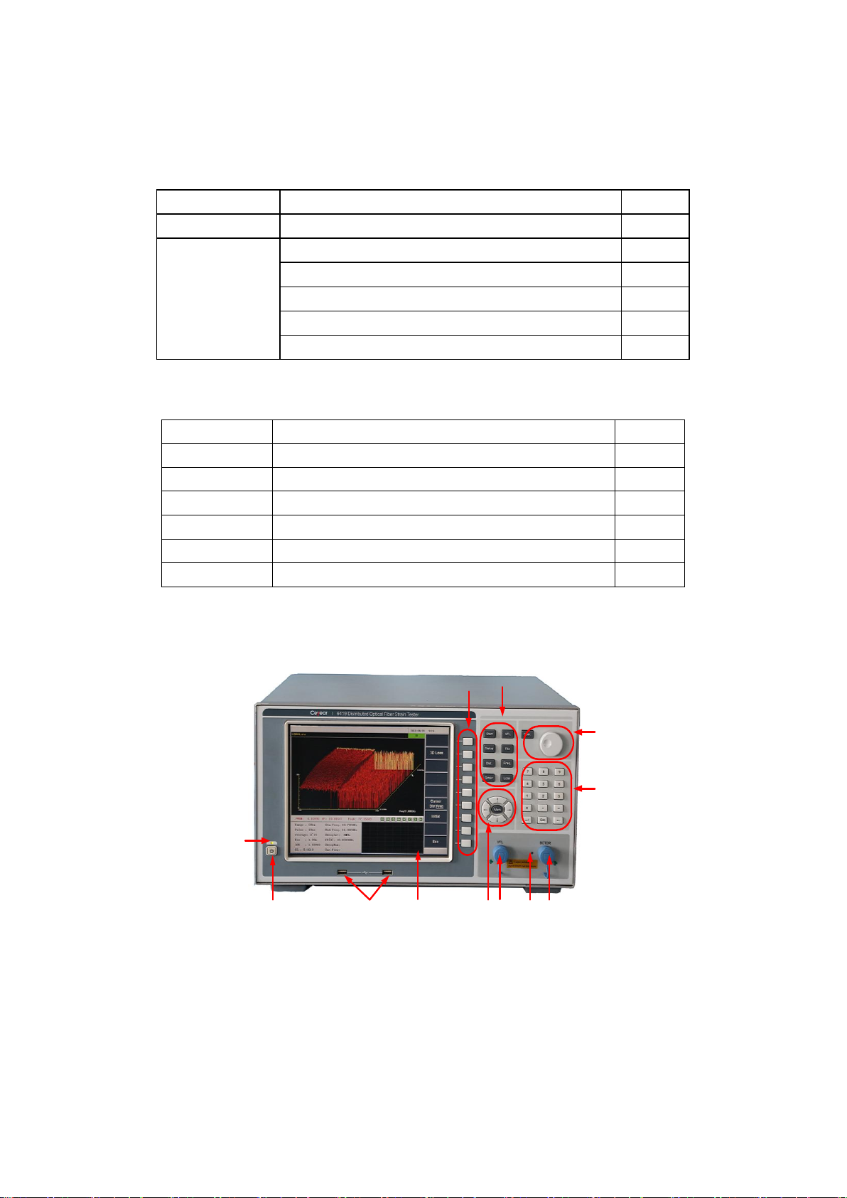
3. Description of instrument panel
3.1 View of instrument front panel
(1)
(2) (3)(4) (5)
(6)(8)(7)
(9)
(10)
(12) (11)
Figure 1-1 Schematic diagram of the front panel of the instrument
Chapter I Overview
7
Table 1-3 Descriptions of the functions of each part of the front panel
No.
Name
Function description
Remarks
(1)
Power indicator
When the power is off, the indicator is off; when the power is on
but the instrument is not turned on, the indicator is orange; when
the instrument is turned on, the indicator is green.
(2)
On/Off button
Used to turn the instrument on and off.
(3)
USB interface
Used to connect USB devices such as USB keyboard, USB mouse
and USB flash drive.
(4)
Touch LCD screen
Used to display measurement information and perform touch
screen operation.
(5)
Navigation button
Including arrow keys and cursor keys, used to scale the test curve
in the test state and move the cursor during test conditions and
system settings.
Detailed in Section
3.1.1
(6)
VFL optical interface
FC/APC interface.
(7)
BOTDR optical
interface
FC/APC interface.
(8)
Laser indicator
Used to indicate whether the laser inside the instrument is running.
(9)
Numeric key area
Used to enter or modify the number, “.”and “-”characters in the
input box of the cursor in the test condition, file operation or
system setting interface.
(10)
Knob keypad
Used to move the cursor for the test curve.
Detailed in Section
3.1.2
(11)
Function keypad
Including 8 common function keys, which can directly and quickly
perform the functions corresponding to the function keys
Detailed in Section
3.1.3
(12)
Menu button
The nine menu buttons correspond to the nine function menus in
the software interface, and the corresponding menu functions can
be executed by pressing the buttons.
Detailed in Section
3.1.4
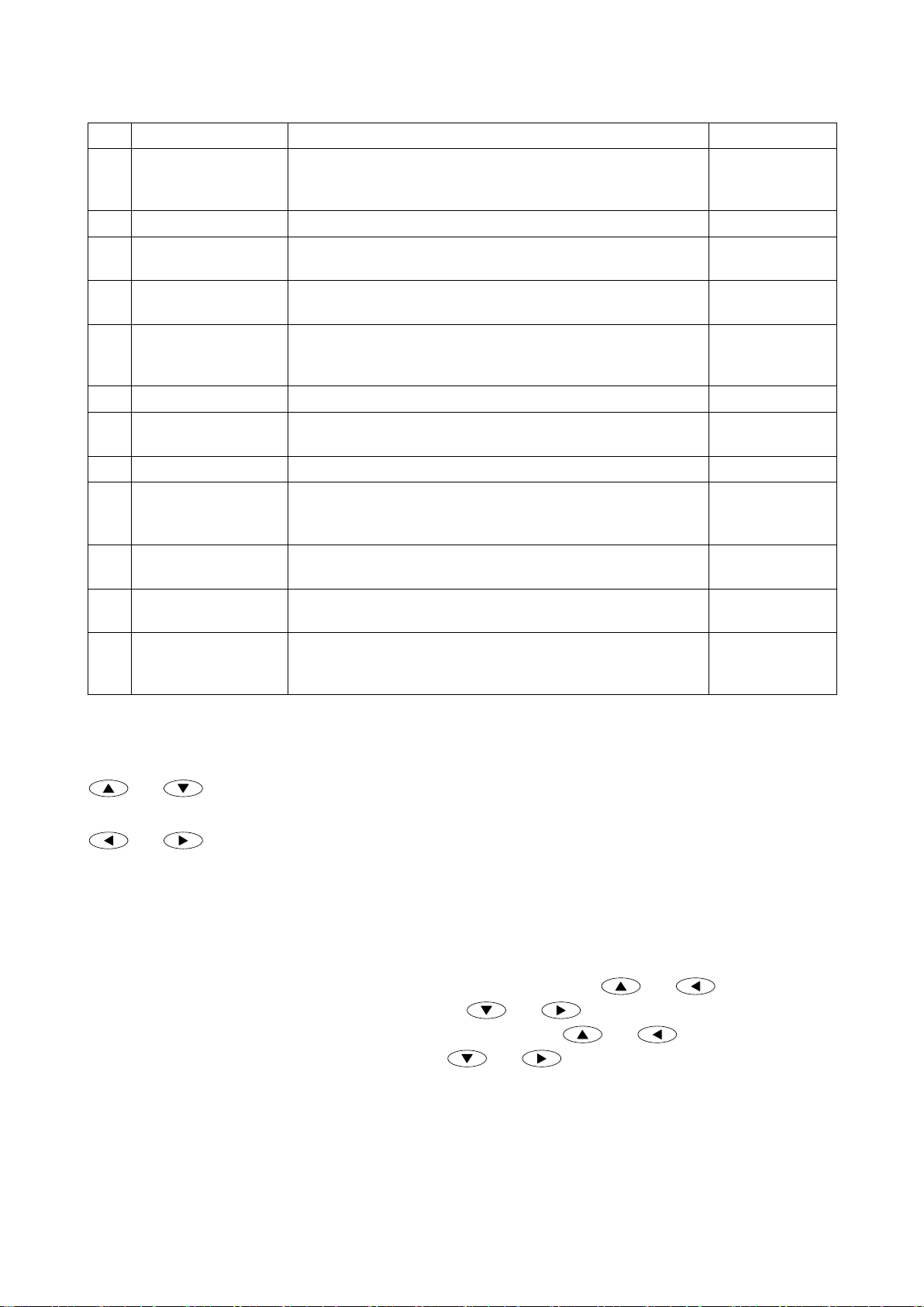
3.1.1 Description of navigation button functions
(1) In the test state, the test curve in the window is scaled around the position of the curve where the cursor is
located:
and are used to expand and compress the vertical coordinate of the test curve in the window display
area respectively. This function is invalid in the "multiwindow" state;
and are used to expand and compress the horizontal coordinate of the test curve with the distance as
the abscissa in the window display area respectively. This function is invalid in the "Brillouin spectrum" state; in
the "multiwindow" state, the cursor in the multiwindow sub-menu is set as the "distance/frequency", and the two
buttons are used for synchronous expansion and compression of the horizontal coordinates corresponding to the
curves of the strain distribution, the distribution of Brillouin scattering spectrum width, and the loss distribution,
respectively.
(2) In the test condition and system setting interface, the cursor button [Cursor] is used to move the cursor in
different parameter setting boxes, if the cursor moves to the drop-down menu, and are used to
display the previous item of the current menu option; and and are used to display the next item of
current menu options. If the cursor is in the radio button or progress bar, and are used to control the
single option or the progress bar to move forward, and and then control the single option or
progress bar to move backward.
3.1.2 Description of knob keypad functions
Knob: It’s used to move the cursor on the test curve in the window display area. When the knob rotates clockwise,
the cursor on the test curve moves right; when the knob rotates counterclockwise, the cursor on the test curve
moves left.

Chapter I Overview
8
Coar.
Coar.
:
Coar.
Coar.
button is used to switch between the normal movement mode and the fast movement mode of the
knob. If the knob is in the normal movement mode, the distance the cursor moves each time is 1 unit horizontal
coordinate; if the knob is in the fast movement mode, the distance each time the cursor moves is 10 unit horizontal
coordinates.
3.1.3 Description of function keypad functions
Test
Test
: Perform/stop the average processing test. When the instrument is performing an average processing test,
using this button will stop the average processing test; when the instrument is in the non-average processing test
state, using the test button will start the averaging processing test.
VFL
VFL
: Pop-up VFLcontrol dialog box, providing fault location function of visual cable for users to select among
four VFL working states of OFF, CW, 1Hz and 2Hz.
Setup
Setup
: Press this button to enter the test condition setting interface (this button is invalid when system setting or
file operation is in progress).
File
File
: Press this button to enter the file operation sub-menu (this button is invalid when the test condition setting
or system setting is in progress).
Dist.
Dist.
: Switch the corresponding mode of the current horizontal cursor to the distance mode.
Freq.
Freq.
: Switch the corresponding mode of the current horizontal cursor to the frequency mode.
Strain
Strain
: Switch the current window to the "strain distribution" state automatically, showing only the "strain
distribution" window.
Loss
Loss
: Switch the current window to the "comprehensive loss" state automatically, showing only the
"comprehensive loss" window.
3.1.4 Description of menu button functions
The menu button corresponds to the function menu button on the right side of the 6419 BOTDR software interface.
If you want to execute the menu item of the function menu being displayed on the software interface, just press
the menu button of its corresponding position.
3.2 View of instrument back panel
Figure 1-2 Schematic diagram of the back panel of the instrument
(1) LAN interface (2) VGA interface (3) RS232 interface (4) USB interface (5) Headphone jack (6) Power
interface (7) Power switch. The description of corresponding functions of each part of 6419 BOTDR back panel
are shown in Table 1-4 (The picture is for reference only, the actual products shall prevail).
Table 1-4 Descriptions of the functions of each part of the back panel
No.
Name
Function description
Remarks
(1)
LAN interface
A network cable can be used to connect the instrument to the network or
directly to other computers.
(2)
VGA interface
The VGA cable can be used to connect the instrument to external display.
(3)
RS232 interface
The RS232 serial cable can be used to communicate with other computers or
serial devices.
(1) (2) (3) (4) (5)(6) (7)

Chapter I Overview
9
(4)
USB interface
Used to connect USB devices such as USB keyboard, USB mouse, and USB
flash drive.
(5)
Headphone jack
Used to connect to headphones.
(6)
Power switch
Used to turn the power of the instrument on/off.
(7)
Power interface
Used to connect the power cord. Power cord
Chapter II Description of Operation Interface
10
Chapter II Description of Operation Interface
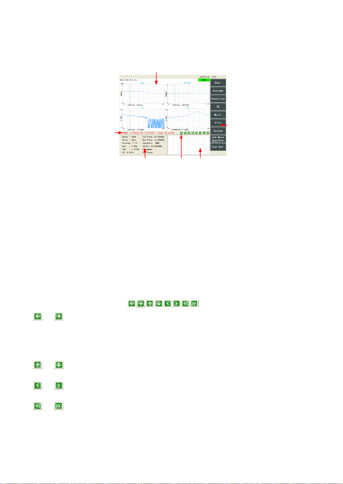
1 Main operation interface
The main operation interface of the 6419 BOTDR is shown in Figure 2-1.
(1)
(2) (3) (4)
(5)
(6)
Figure 2-1 Schematic diagram of the main operation interface
The operation interface of 6419 BOTDR instrument is divided into six areas: (1) Test result area, (2) Test
condition area, (3) Waveform operation area, (4) Sub-waveform window, (5) Function menu area and (6) Window
display area, the specific information is described as below.
1.1 Test result area
This area is used to display some results of the 6419 BOTDR test, which has the following meanings:
FWHM: Indicates the Brillouin spectrum bandwidth of the current distance point;
fB: Indicates the center frequency of the Brillouin spectrum fitting curve of the current distance;
Peak: Indicates the peak relative power of the Brillouin spectrum at the current distance point.
1.2 Test condition area
This area is used to display the test conditions or Marker information of the instrument. When the software is in
the Marker sub-menu, the Marker information will be displayed in this area. In other cases, the test condition of
the instrument will always be displayed in the area. See Section 2 in Chapter 3 for details.
1.3 Waveform operation area
The waveform operation area includes buttons, with the following functions:
and : In the "strain distribution" state, the "spectral width distribution" state, the "loss distribution" state,
and the "comprehensive loss" state, it’s used to compress or expand the horizontal coordinate of the test curve
with the cursor as the center in the window display area. When the [cursor] in the in the multiwindow sub-menu is
set as the "distance/frequency", the two buttons are used for synchronous expansion and compression of the
horizontal coordinates corresponding to the strain distribution, the spectral width distribution, and the loss
distribution curves, respectively.
and : It’s used to expand and compress the vertical coordinate of the test curve with the cursor as the
center in the window display area respectively. This function is invalid in the "multiwindow" state;
and : It’s used to control the cursor to move left or right on the measurement curve of the window display
area, moving 1 horizontal unit at a time.
and : It’s used to control the cursor to move left or right quickly on the measurement curve of the window
display area, moving 10 horizontal units at a time.
The [Cursor] button setting in the function menu determines whether the horizontal coordinate controlled by the
waveform operation button control is the distance or frequency mode, and other corresponding operations will be
triggered according to the operation for the selected horizontal coordinates (for details, see "Chapter IV
Chapter II Description of Operation Interface
11
“Description of Window Display”) .
1.4 Sub-waveform window
When the window display area is in the "strain distribution" state, the "spectral width distribution" state, the "loss
distribution" state, and the "comprehensive loss" state, the sub-waveform window displays the Brillouin spectrum
curve on the cursor of the global curve or curve of the measurement curve according to the setting of the
[Sub.Wave] function button in the main function menu.
The sub-waveform window in the Brillouin spectrum state is displayed as a strain distribution global curve.
1.5 Function menu area
This area is used to display the function menu of the software. Each function menu button has a one-to-one
correspondence with the menu buttons on the front panel of the instrument. The corresponding function menu
buttons can be selected by pressing the front panel menu button of the instrument to realize the functions, or the
corresponding functions can be performed by clicking the function menu buttons with the mouse or through the
touch screen.
1.6 Window display area
In the "multiwindow" state, "strain distribution" state, "spectral width distribution" state, "Brillouin spectrum"
state, "loss distribution" state, "comprehensive loss" state, and "3D" state, this area is used to display the
measurement curve in the corresponding state; the corresponding setting interface is displayed when setting the
test condition, file operation and system.
2 Structure and function of main menu
The function menu displayed by default in the main operation window after the instrument is turned on is the
main function menu, including [Real-time Test], [Average], [Test condition], [3D display], [Multiwindow], [File],
[System] and [Sub.Wave].
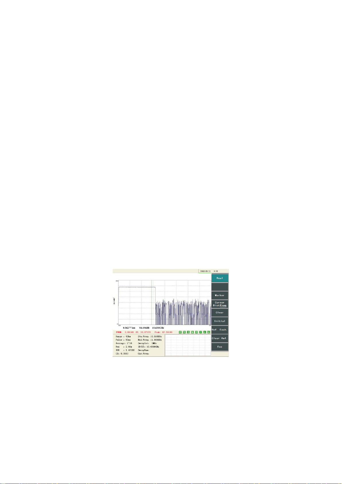
[Real-time Test]: The instrument starts/stops testing the real-time loss distribution curve at the selected sweep
frequency. The real-time test allows the sweep frequency of the test to be changed at any time during the test,
which is convenient for quickly determining the optimal start frequency condition for the average processing test.
This function does not stop automatically after execution. If the real-time test is not stopped, the test will continue
until the instrument is turned off. Figure 2-2 shows the loss distribution curve under real-time test. The knob
button on the front panel of the instrument is used to change the sweep frequency of the real-time test.
Figure 2-2 Loss distribution curve under real-time test
[Average]: The instrument starts/stops the average processing test function to test the loss distribution curve of the
fiber under test. The average processing test function calculates the strain distribution curve of the fiber under test
by testing the loss distribution curve at the sweep frequency point from the start frequency to the cut-off frequency,
so the function will automatically stop after the test is completed after execution. Figure 2-3 shows the loss
distribution curve under the average processing.
Chapter II Description of Operation Interface
12
Figure 2-3 Loss distribution curve under average processing
[Test condition]: After entering the test condition setting interface shown in Figure 2-4, the measurement
conditions and parameters related to the 6419 BOTDR measurement process can be set, and the function menu
area will display the test condition sub-menu (for details, see "Chapter III Description of Test Conditions").
Figure 2-4 Interface of test condition
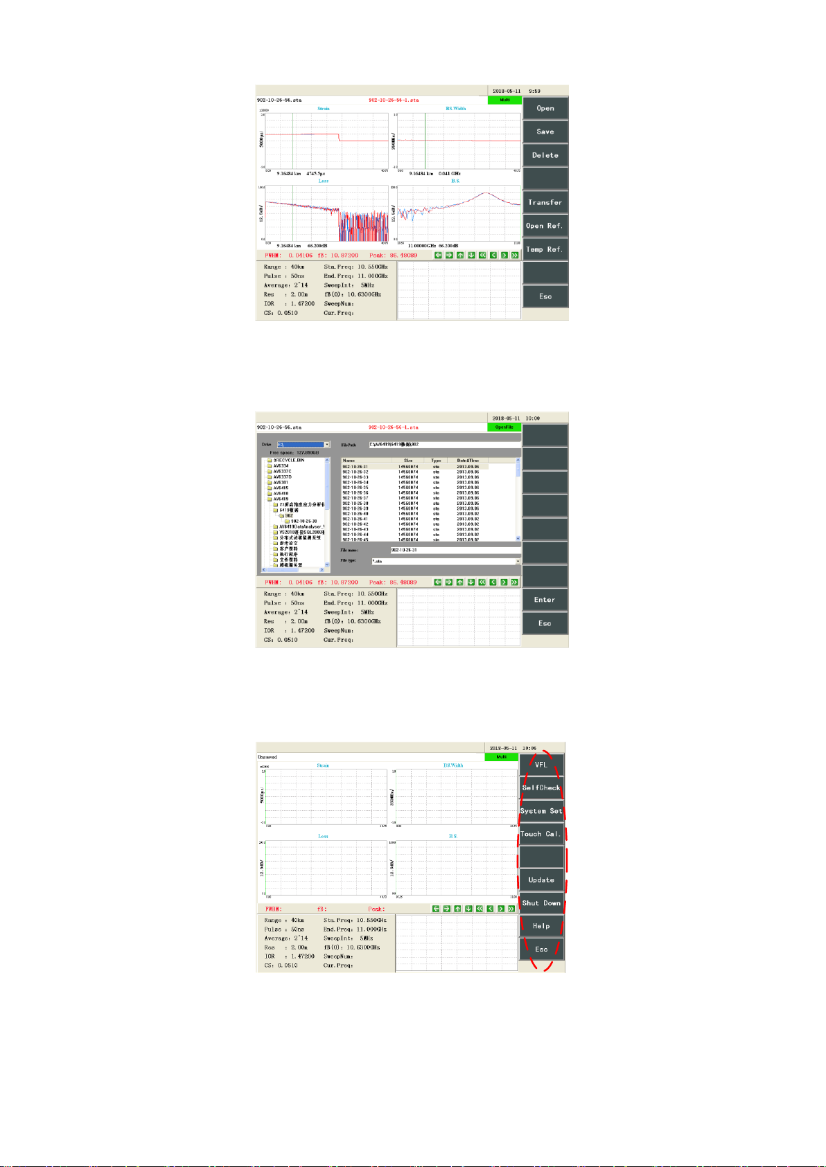
[3D display]: The window display area will enter the “3D”status interface shown in Figure 2-5. Only the “3D”
window will be displayed. The function menu area will display the sub-menu in the 3D state (for details, see
“Chapter V Description of 3D Display Functions”).
Figure 2-5 Interface of 3D state
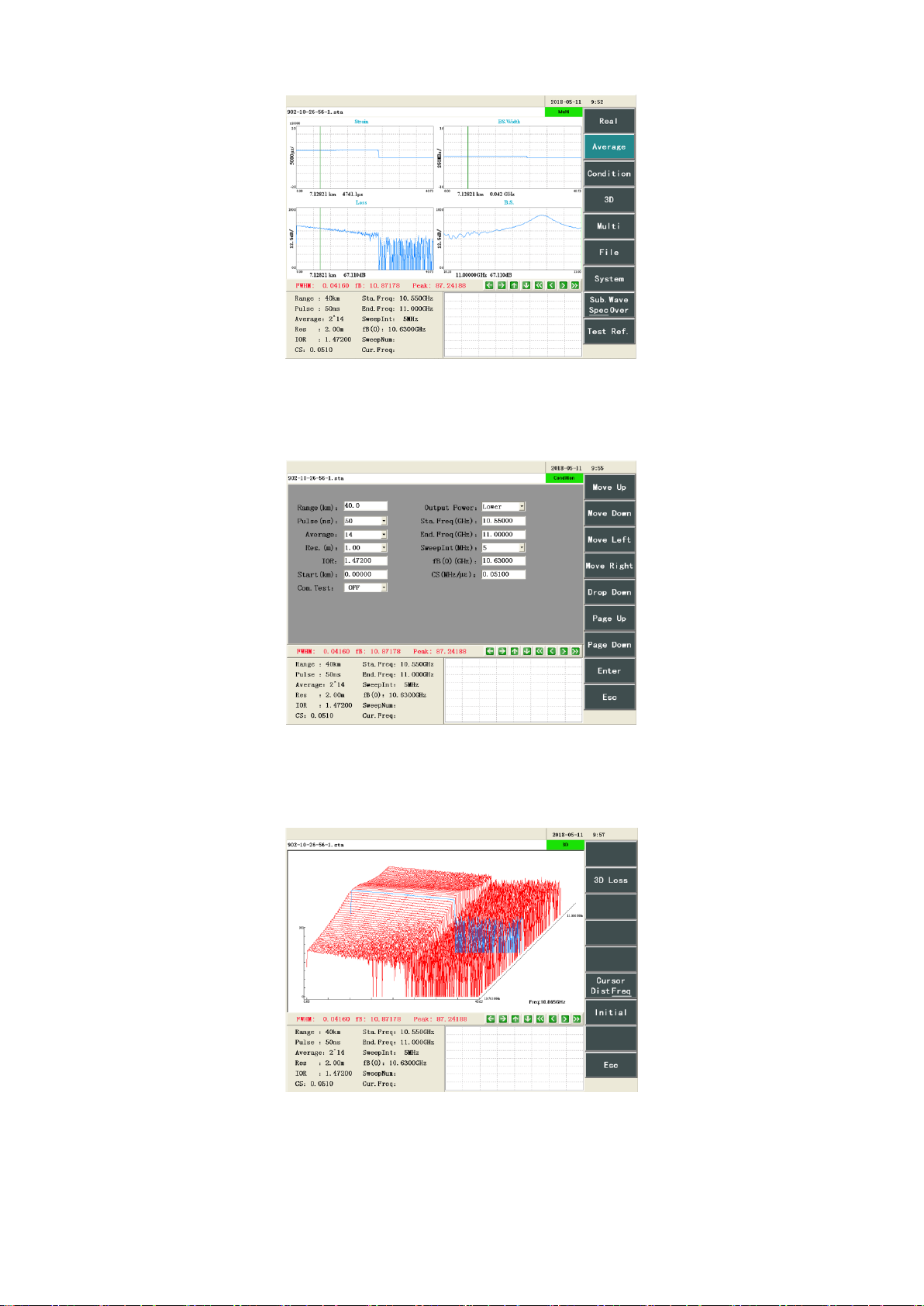
[Multiwindow]: The window display area will enter the "multiwindow" state shown in Figure 2-6, and the "strain
distribution" window, the "spectral width distribution" window, the "Brillouin spectrum" window, and the "loss
distribution" window will be displayed. The function menu area will display the sub-menu in the multiwindow
state (for details, see "Chapter IV Description of Window Display").
Chapter II Description of Operation Interface
13
Figure 2-6 Interface of multiwindow state
[File]: After entering the file operation interface, the function menu area will display the file sub-menu to can
open the file, save the file and open the reference file, as shown in Figure 2-7 (for details, see "Chapter VI
Description of File Functions").
Figure 2-7 Interface of opening file
[System]: The function menu area will display the system sub-menu (as shown in Figure 2-8). The 6419 BOTDR
system function can be used and set according to the menu function provided (for details, see “Chapter VII
Description of System Menu”).
Figure 2-8 Function menu area showing the system sub-menu
[Sub.Wave]: It is used to set the display contents in the sub-waveform window (as shown in Figure 2-9). If the
button is displayed as “global Brillouin spectrum”, it indicates that the sub-waveform window will display the
global test curve; if the button is displayed as “global Brillouin spectrum”, it indicates that the sub-waveform
window will display the spectrum curve at the distance point where the cursor is located. In the “Brillouin
Table of contents
Other Ceyear Test Equipment manuals


