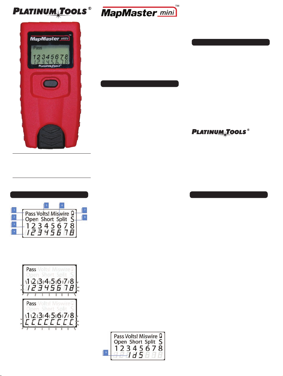
manuals.online logo
Brands
  1. Home
  2. •
  3. Brands
  4. •
  5. Platinum Tools
  6. •
  7. Test Equipment
  8. •
  9. Platinum Tools MapMaster mini User manual

Platinum Tools MapMaster mini User manual

MapMaster™ mini
Instructions: P/N T109
Cable tester
•
EASYTOUSE
•
EASYTOREADLCDSCREEN
•
DETECTSSHORTS,OPENS,REVERSALS,MISWIRES,
AND SPLIT PAIRS
•
TONEGENERATOR
•
REMOTEIDDETECTION
•
AUTOPOWER-OFF
GENERAL SPECIFICATIONS
The Platinum Tools MapMaster mini is a pocket-size data
cable tester. It tests and troubleshoots RJ45 terminated
cables, provides built-in tone generation for cable tracing
and detects either two test and mapping remotes and up to
five network ID remotes for mapping end locations.
•
•
•
•
•
•
•
•
•
Dimensions:4.6”x2.3”x1.1”(11.7x5.8x2.8cm)
Weight:4.0oz.(115grams)withbatteryandremote
OperatingTemperature:0°Cto50°C/32°Fto122°F
StorageTemperature:-20°Cto60°C/-4°Fto140°F
Humidity:10%to90%,non-condensing
MaximumVoltagebetweenanytwoconnectorspins
without damage: RJ Jack: 66V DC or 55V AC
BatteryLifetypical:6Valkalinebatteries-4xLR44,
Standby:3.5years,Active:80hours
CableTypes:ShieldedorUnshielded;CAT7,CAT6a,
CAT5e,CAT5,CAT4,CAT3(4-paironly)
MaximumRJCableLength:0to1000feet(305meters)
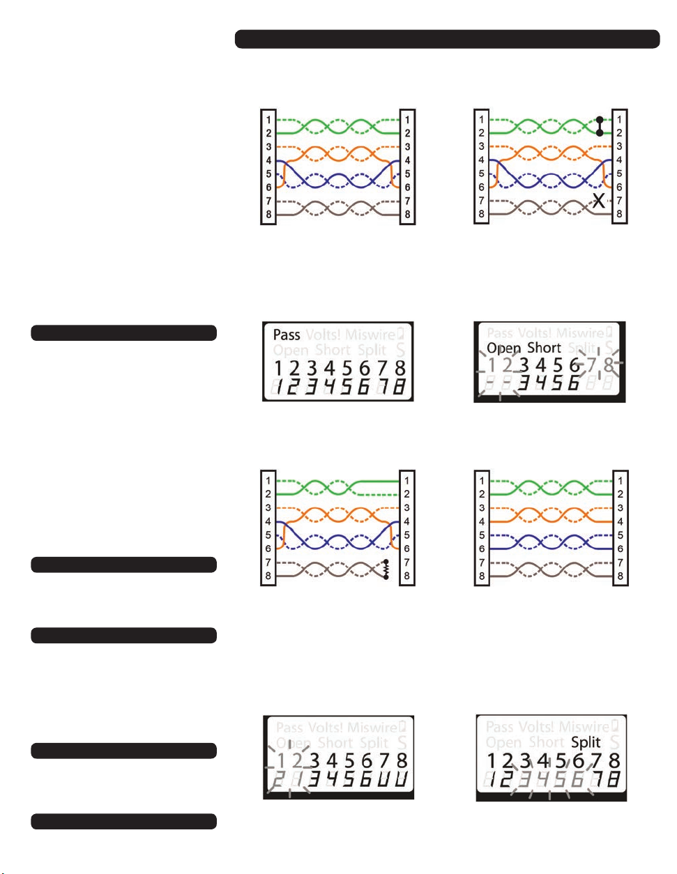
4. Tester-End Wire Map: The top line displays the pins on
the tester end in order. These pins are mapped to the
pins on the remote-end shown directly below them on
the LCD.
5. Remote-End Wire Map: The lower row displays the
corresponding pin on the remote-end. Dash lines on
the remote line indicate shorted pins. No pin numbers
displayed on the remote line are open pairs.
6. Voltage Detected Warning: If voltage is detected on any
of the tester connectors, the “Volts!” icon is displayed.
A check for voltage is performed before each test and if
found, no test is run. The tester should be disconnected
immediately from the source of the voltage.
7. Battery Low: The battery low symbol is displayed when
the battery is nearing depletion. The symbol will begin
to flash when the batteries need to be replaced. Results
may be unreliable at this point.
8. Shield: The “S” icon is displayed when a shielded data
cable is properly connected at both ends. It will be flash-
ing if there is a short to a wire in the cable along with
that pin number and the “Short” indicator.
9. ID number: When used with the #2 test-and-map remote
in the CABLE mode alternately displays the lower row
wire map and “ID 2” or when using the network map-
only remotes (#1– #5) in the LOCATE mode, displays the
ID number of the remote.
The MapMaster mini has a single button to both start a test
and select other functions and options. Presses of less than
about 1 second (short press) and more than 1 second (long
press) are recognized differently.
1.Cable testing (short press)
With the MapMaster mini off, each short press of the
button causes a cable test to be executed and the results
displayed for 20 seconds before powering off. “TEST”
is displayed while testing is being performed. If another
short press occurs before the 20 second time out another
test and 20 second time out begin.
If the button is pressed and held until “LOOP” is displayed
and then released, tests are run continuously, and the
display updated. The MapMaster mini will turn off auto-
matically if there is no test result change for 5 minutes.
A long press of the button will cause the MapMaster mini
to exit cable test loop mode and enter mode selection as
discussed below.
Mode Selection (long press): Starting with the MapMaster
mini off, a long press of the button will cause the Map-
Master mini to enter mode selection. In mode selection
the MapMaster mini cycles through cable test and tone
generator modes. The mode displayed when the button
is released will begin execution. From powered off, the
modes in order are:
LOOP -> LOCATE -> HiLo1 -> HiLo2 -> Hi ->
Lo -> OFF -> CABLE
• Loop: Cable test that loops continuously until it times out
or exiting the mode by a long press that reenters mode
selection. Used to troubleshoot intermittent problems.
Display
1. Pass: “Pass” flashes if the cable is a properly wired
4-pairT568A/Bdatacableorcross-over(uplink)cable.A
cross-over cable will have the lower row of pin numbers
of the crossed pairs flashing and will alternate with “C”.
2. Cable Faults: The “Miswire” icon is displayed if the cable
is not wired to one of the cabling standards. An open
or short error takes precedence over miswires and the
appropriate icon(s) is displayed.
3. The“Split”iconisdisplayedifthedesignatedpairsare
not twisted together in the cable, an AC signal fault.
We Make Connections EZ!™
©2018 Platinum Tools, Inc. All rights reserved.
MapMasterminiIST109GJ12/18
Operating the MapMaster™mini Cable Tester
•
•
•
MinimumCableLengthforSplitPairDetection:1.5feet
(0.5 meters)
LowBattery:Iconflasheswhenbatteryvoltagefalls
below 6V
ComplieswithConformitéEuropéennedirectives.
WARNINGS
To ensure safe operation and service of the tester, follow
these instructions. Failure to observe these warnings can
result in severe injury or death.
•
•
TheMapMasterminiisdesignedforuseonunenergized
cabling systems. Connecting the MapMaster mini to live
AC power may damage it and pose a safety hazard for
the user.
PoorlyterminatedRJplugshavethepotentialtodamage
the jacks on the MapMaster mini. Visually inspect an RJ
plug before inserting it into the tester. The contacts
should always be recessed into the plastic housing of the
plug. Plugging 6-position plugs into the 8-position jack on
the tester has the potential to damage the outer-most
contacts of the jack unless the plug is specifically
designed for that purpose.
Test Equipment Depot - 800.517.8431
99 Washington Street, Melrose, MA 02176
TestEquipmentDepot.com
T568B is electrically identical to T568A but swaps
the green and orange pairs. Either standard will
work as long as the same standard is used at both
ends of a run or patch cable. Mixing “A” and “B”
creates a cross-over cable.
The 1–2 pair pins are shorted together, and the
7–8 pair is open. The pins with the errors are
flashing. Dash lines (-) on the bottom (remote)
display line indicate the short, while no numbers
on the bottom line indicate the open pair.
1 and 2 pins on the MapMaster mini are con-
nected to pins 2 and 1 at the remote-end. The
pins with this error are flashing. The “U” for the
remote pin numbers indicates an unrecognizable
continuity was detected that is neither a short or
open. An ID remote connected to the MapMaster
mini when in cable test mode would also show
this error.
A common error in building a cable is to put all
thepairsinpinsequence1–2,3–4,5–6and
7–8. This will produce the correct continuity,
butthepairsaredesignatedtobeonpins3–6
and 4–5 in the middle of the connector for
compatibility with phone wiring. This wiring error
is only detected by the split pair test since the
designated pairs are not twisted together.
• Locate: Detects network map-only ID remotes #1–#5.
This mode is not used to test cables but is used only to
map the location of the jack that the far end is connected
to using the map-only ID remotes. For testing cables use
the master remote stored in the bottom of the tester.
• Hi Lo 1, Hi Lo 2, Hi, Lo (four tone cadences): The four
modes are all tone generator modes with different
sounds.The“HiLo”tonesaremadeupoftwofrequencies
withdifferenttimings.“Hi”and”Lo”aresinglefrequency.
Once in a tone mode, short presses change the pins
carrying tone. The pins with tone are displayed. In a tone
mode,thetesterwillturnoffautomatically30minutes
after the last button press or by exiting to mode select
with a long press. Note that you must use an analog tone
probe to hear the tones generated by the tester.
• Off: When the button is released with “OFF” displayed,
the Tester will power off. Once in one of the above
modes, OFF is the first mode offered upon exiting to
mode select. To select a different mode other than OFF,
continue to hold the button down and the next mode in
rotation will be displayed next.
• Cable: The cable test mode is the single cable test mode
with 20 second timeout that a short press from powered
off executes.
Warranty
Platinum Tools warrants this product to be free from defects
in material and workmanship for 12 months for test equip-
mentand3monthsforcablesandaccessoriesfromthedate
of purchase. Liability is limited to the repair and or replace-
ment of the product. Warranty excludes batteries and wear-
able components such as the integrated RJ45 jack included
withtheproduct.NOIMPLIEDWARRANTIESOFMERCHANT-
ABILITYORFITNESSFORAPARTICULARPURPOSE.Platinum
Tools is not liable for consequential damages.
Should any parts or workmanship prove defective, Platinum
Tools will repair or replace at Platinum Tools’ option, at no
cost to the Buyer except for shipping costs from the Buyer’s
location to Platinum Tools. This is Buyer’s SOLE AND EXCLU-
SIVEREMEDYunderthisAgreement.Thiswarrantydoesnot
apply to products which have been subject to neglect, ac-
cident or improper use, or to units which have been altered
or repaired by other than an authorized repair facility.
Cleaning
Turn off the MapMaster mini and disconnect all cables. Use
a damp, clean cloth to clean the MapMaster mini. CAUTION:
do not use abrasive or harsh cleaners or solvents.
Storage
When the MapMaster mini is not in use, store in a dry,
protective case. Batteries should be removed if stored for a
long period of time. Do not expose to high temperatures or
humidity. When stored in temperatures exceeding the limits
listed in the Specifications section, allow the MapMaster
mini to return to normal recommended operating conditions
before using it.
Disposal
Caution: This symbol indicates that equipment and its
accessories should be treated to a separate collection and
proper disposal.
Warning
Always wear approved eye protection. Do NOT use on
live circuits
Tester
Tester
Tester
Tester
Remote
Remote
Remote
Remote
Properly Wired T568A UTP: T568A Cable with a Short and Open:
T568A Cable with a Misfire and
Unrecognized Continuity:
T568A Cable with Split Pairs:
WIRING AND DISPLAY EXAMPLES
Test Equipment Depot - 800.517.8431
99 Washington Street, Melrose, MA 02176
TestEquipmentDepot.com

This manual suits for next models

1

Other Platinum Tools Test Equipment manuals

Platinum Tools Fault Trapper TFT100 User manual

Platinum Tools

Platinum Tools Fault Trapper TFT100 User manual

Platinum Tools Net Prowler TNP800 User manual

Platinum Tools

Platinum Tools Net Prowler TNP800 User manual

Platinum Tools Net Prowler TNP700 User manual

Platinum Tools

Platinum Tools Net Prowler TNP700 User manual

Platinum Tools VDV MapMaster User manual

Platinum Tools

Platinum Tools VDV MapMaster User manual

Platinum Tools NETXPERT XG2 User manual

Platinum Tools

Platinum Tools NETXPERT XG2 User manual

Platinum Tools Fault Trapper TFT100 User manual

Platinum Tools

Platinum Tools Fault Trapper TFT100 User manual

Platinum Tools Cable Prowler TCB400 User manual

Platinum Tools

Platinum Tools Cable Prowler TCB400 User manual

Platinum Tools VDV MapMaster 2.0 User manual

Platinum Tools

Platinum Tools VDV MapMaster 2.0 User manual

Platinum Tools TP220 User manual

Platinum Tools

Platinum Tools TP220 User manual

Platinum Tools Net Chaser TNC950AR User manual

Platinum Tools

Platinum Tools Net Chaser TNC950AR User manual

Platinum Tools NETXPERT XG2 User manual

Platinum Tools

Platinum Tools NETXPERT XG2 User manual

Popular Test Equipment manuals by other brands

Hama 87696 operating instructions

Hama

Hama 87696 operating instructions

BOLDAN Miniroller D200 e manual

BOLDAN

BOLDAN Miniroller D200 e manual

Presys TA-1200PLAB Technical manual

Presys

Presys TA-1200PLAB Technical manual

GE Druck DPI 610 user manual

GE

GE Druck DPI 610 user manual

Wavecom TnP-500X user manual

Wavecom

Wavecom TnP-500X user manual

Hanna Instruments HI510 instruction manual

Hanna Instruments

Hanna Instruments HI510 instruction manual

HELIO-STROB tripLED Operation manual

HELIO-STROB

HELIO-STROB tripLED Operation manual

Mitutoyo ABS DIGIMATIC user manual

Mitutoyo

Mitutoyo ABS DIGIMATIC user manual

G.R.A.S. 42AG instruction manual

G.R.A.S.

G.R.A.S. 42AG instruction manual

HeartSciences MyoVista Wavelet ECG user manual

HeartSciences

HeartSciences MyoVista Wavelet ECG user manual

Hameg HM2005-2 user manual

Hameg

Hameg HM2005-2 user manual

Pilz PSS Series operating manual

Pilz

Pilz PSS Series operating manual

CATU PE C'diAG Touch Instructions for use

CATU

CATU PE C'diAG Touch Instructions for use

Sartorius mLINE user manual

Sartorius

Sartorius mLINE user manual

HD Electric FACT-1 Operating instructions manual

HD Electric

HD Electric FACT-1 Operating instructions manual

Hantek DSO1000S Series user manual

Hantek

Hantek DSO1000S Series user manual

Tektronix TDS 510A instruction manual

Tektronix

Tektronix TDS 510A instruction manual

Powerfix Profi 115001 Operation and safety notes

Powerfix Profi

Powerfix Profi 115001 Operation and safety notes

manuals.online logo
manuals.online logoBrands
  • About & Mission
  • Contact us
  • Privacy Policy
  • Terms and Conditions

Copyright 2025 Manuals.Online. All Rights Reserved.