Ceyear 4992A User manual
I
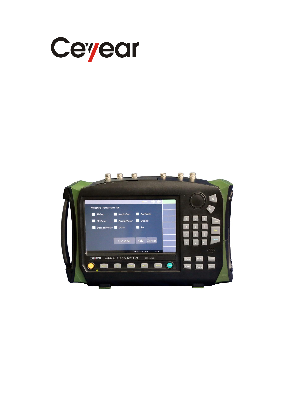
4992A Radio Test Set
User Manual
China Electronics Technology Instruments Co., Ltd

Preface
Thank you for purchasing and using 4992A Radio Test Set developed and produced by China
Electronics Technology Instruments Co., Ltd.
We take meeting your demands as our mission and while offering high quality instruments,
we also provide you with technical support and after-sales services. If you have any questions,
please don't hesitate to contact us:
Tel
+86-0532-86896691
Website
www.ceyear.com
E-mail
sales@ceyear.com
Address
NO. 98 Xiang Jiang Rd., Qingdao City, China
Zip code
266555
This manual describes the purpose, operation method, precautions, performance
characteristics, basic working principle, fault query, etc. of 4992A Radio Test Set developed and
produced by China Electronics Technology Instruments Co., Ltd, so as to help you rapidly
understand the methods and key points of operation of this instrument. For proper use, please read
this manual carefully and properly observe the guidance.
This user manual includes eight chapters in total.
Chapter I provide and overview of 4992A Radio Test Set, including main technical
characteristics, existing or available functions and technical indicators.
Chapter II to V mainly describe the operation. Chapter II describes how to handle a new
Radio Test Set as well as the precautions during operation. Chapter III mainly introduces the front
panel, external interfaces, etc. Chapter IV introduces the basic operations of 4992A. Chapter V
introduces the menus of 4992A, which are arranged according to the function categories to
facilitate access.
Chapter VI and VII introduce technical requirements, including a brief description of the
working principle of 4992A and an introduction to the performance test methods of main technical
indicators.
Chapter VIII introduces maintenance requirements, including fault query steps, error
information and repair methods.
Statem
ent:
This manual is the first version (No. AV2.766.1002SS/A.2) of User Manual
of 4992A Radio Test Set.
The information contained in this User Manual is subject to change
without notice.
The power to interpret the contents of and terms used in this Manual rests
with China Electronics Technology Instruments Co., Ltd.
China Electronics Technology Instruments Co., Ltd owns the copyright of
this User Manual which should not be modified or tampered by any
organization or individual, or reproduced or transmitted for the purpose of
making profit without its prior permission, otherwise China Electronics
Technology Instruments Co., Ltd will reserve the right to investigate and affix
legal liability of infringement.

Due to the limitations in the author’s knowledge, there may be errors or omissions in this
manual. Your comments are highly appreciated. We apologize for any inconvenience that may
rise therefrom.
Editor
January 2018
Table of contents
Other Ceyear Test Equipment manuals


Popular Test Equipment manuals by other brands


Redtech
Redtech TRAILERteck T05 user manual

Venmar
Venmar AVS Constructo 1.0 HRV user guide

Test Instrument Solutions
Test Instrument Solutions SafetyPAT operating manual

Hanna Instruments
Hanna Instruments HI 38078 instruction manual

Kistler
Kistler 5495C Series instruction manual

Waygate Technologies
Waygate Technologies DM5E Basic quick start guide

StoneL
StoneL DeviceNet CK464002A manual

Seica
Seica RAPID 220 Site preparation guide

Kingfisher
Kingfisher KI7400 Series Training manual

Kurth Electronic
Kurth Electronic CCTS-03 operating manual

SMART
SMART KANAAD SBT XTREME 3G Series user manual

Agilent Technologies
Agilent Technologies BERT Serial Getting started