manuals.online logo
Brands
  1. Home
  2. •
  3. Brands
  4. •
  5. Aegis
  6. •
  7. Test Equipment
  8. •
  9. Aegis CZ20053 User manual

Aegis CZ20053 User manual

CZ20053
Operating Manual
 
This operating manual contains warning information and
safety regulations. Please read them carefully and observe them
strictly to ensure the safety of the user and instrument.

1 . Please read and understand the contents of the manual before using the

instrument.
2. Please use the instrument in strict accordance with the test procedure
described in the manual.
3. Please be sure to understand the safety aspects of the manual in detail.
4. This instrument must be operated by a trained and qualified technician
and used under the conditions specified in the manual.
5. Aegis is not responsible for any damages caused by improper use or
violation of the safety regulations in the manual.
Safety symbol has three meanings in the manual. Users should pay
special attention to the operation for the symbol when reading.
A 





 
 



 


  


 
 




Z






2. The instrument tests the connection between the neutral point of the
distribution system and earth before the test is started. A possible voltage
between the conductor and the earth may influence the measurements.
3. The leakage currents in the circuit following the residual current protection
device may influence the measurements.
4. When the fault voltage is over 50V, "Uf Hi" will be displayed and the test will
stop. The voltage relates to the residual operating current of the protective
device.
5. The earth electrode resistance of the measuring circuit probe cannot surpass 5Ω.
6. The potential fields of other earthing installations may influence the
measurement.
7. Special conditions in residual current protective devices shall be taken into
consideration.
8. Equipment is connected downstream of a residual current protective device
The meaning of the symbols associated with this instrument:
  
 
 

1.
Intelligent microprocessor chip control: High accuracy, reliability and stability
2.
RCD Test Wiring Check:

When the wiring is correct, the L-PE and
L-N
symbols on the left side of the
LCD are always on.

If the power is abnormal or no power, the L-PE and L-N symbols on the left
side of the LCD will flash simultaneously.

If the power socket is not well grounded or not grounded, the L-PE and N-
PE symbols on the left side of the LCD will flash simultaneously.

If the neutral line of the power socket is not well connected or not connected,
the N and N-PE symbols on the left side of the LCD will flash simultaneously.

If the live wire and neutral line of the power socket are inversely connected,
the L-PE,
L-N,
and N-PE symbols on the left side of the LCD will flash
simultaneously.
    
    
    
    

   
   


3. Phase angle selection: The RCD test can be selected to start from a positive
(0
°
) or a negative (180
°
) half cycle.
4. Contact voltage alarm: The contact voltage can be limited to UL25V or UL50V.
When the contact voltage is larger than the selected limit value during the
RCD test, the RCD test will be stopped and the LCD will display "Hi" and "Uf'.
5. Auto data hold: After RCD test, the measurement results are kept displayed
until a button press or rotatory switch change.
6. Over range indication: When the test value exceeds the maximum or
minimum value of the current test range, the LCD will display "> current
maximum value" (such as >300ms) or "< current minimum value"
(such as <30V).
AEGIS
7. AUTO RAMP test: Test the trip current and trip time simultaneously.
8. Battery powered: 6 x 1.5V AA alkaline battery. There will be low
voltage indication when the battery voltage falls below 7.2V.
9. Auto Power Off function: The instrument will be power off automatically
after no operation for 5 minutes.
10. Fuse safeguard
11. Double or reinforced insulation for safe design.
12. Backlight function: Press the "LIGHT" key and power on the instrument
to tum the backlight on; In the "VOLTS" position, press the "LIGHT" key
to turn the backlight on/off.
13. L-N voltage measurement: Display L-N input voltage. The display range
is 30V~600V. "---" is displayed when there is no input or the input
is
extremely low, "<30V" is displayed when the input is less than 30V,
and ">600V" is displayed when the input is larger than 600V. Press the
"L-
N/L-PE" button to switch to L-PE voltage display.
14. L-PE voltage measurement: Display L-PE input voltage. The
display
range is 30V-600V. "----" is displayed when there is no input or the input
is extremely small, "<30V" is displayed when the input is less than 30V,
and ">600V" is displayed when the input is larger than 600V. Press the
"L-N/L-PE" key to switch to L-N voltage display.
15. Frequency measurement: Display the input frequency of the
L-PE
terminal. In the "VOLTS" position, press the 'VOLT/FREQ" button
to switch the voltage/frequency display.

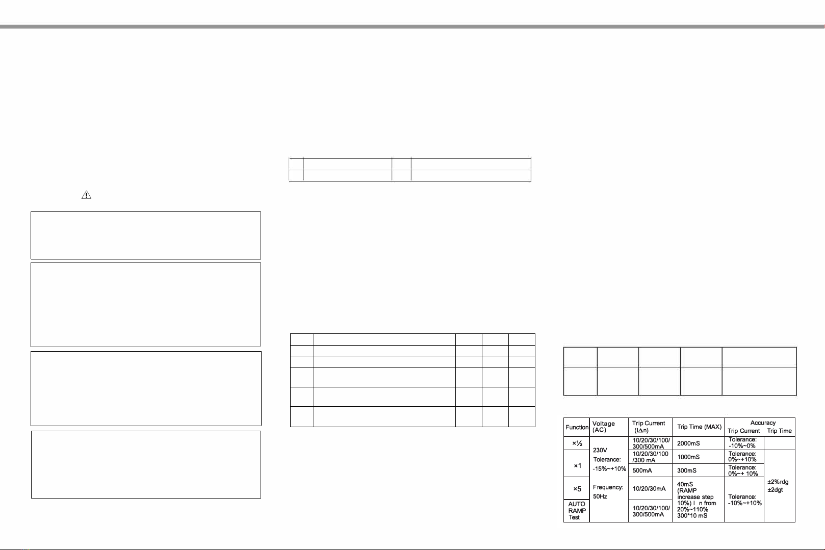
1. Measurement Range and Measurement Accuracy (Temperature: 23±5
°
C;
Humidity: 45%-75% RH; Altitude ≤2000m)

    
  

    


    
(AC) 
  
 

- 

x1   

-
x5    
-
 

  

   
  
  
 
If the neutral line of the power socket is
not well connected or not connected
Tolerance:
0%~+10%
 

A 
A 

Warnings:
1. A possible voltage between the protective conductor and earth will
influence the measurements.
CZ20053
RCD TESTER
1. LCD
2. PHASE/UL key (RCD function) L-N/L-PE button
(voltage measurement function)
3. IΔn button (RCD function) LIGHT button (Backlight function)
4. TEST button (RCD function) VOLT/FREQ button
5. Function selection switch
6. Test ports
7. Three terminals test lead
8. Test lead
VV/qMm
1. Please use the supplied test leads to test the voltage (The maximum voltage
which being tested should be less than 600V).
Test Lead connection method: Insert the red test lead into L port and black test
lead into N port of the instrument.
Note: If the voltage is less than 250V,
you
can use the 3 terminals test lead but it is not recommended.
Three terminals test lead connection method: Insert the three terminals of the
test lead into the three corresponding ports of the instrument. Red into L,
Green into E and Blue into N.
2. Turn the function switch to the 'VOLTS' position, then power up the
instrument.
3. Press the "L-N/L-PE" button to switch between L-N/L-PE voltage display.
4. Press the "VOLT/FREQ" button to switch between voltage/frequency display.
V RCDT
1. Test Lead Connection:
Insert the three terminals of the test lead into the three corresponding ports of
the instrument. Red into L, Green into E and Blue into N. Turn the function
switch to the desired current multiplier (x1/2, x1, x5 or AUTO RAMP) of the
RCD test function. Then connect the plug of the test lead into the circuit to be
tested (power socket 230V/50Hz).
2. Wiring Check:
Verify the wiring status by observing the L-PE, L-N and N-PE symbols. When
the wiring is correct, the L-PE and L-N symbols on the left side of the LCD are
always on and the N-PE is off. Otherwise, the wiring is incorrect; check and
correct the relevant wiring until correct wiring indication is obtain.
Caution: Reverse connection between E and N ports during wiring check may
cause RCD to trip. In this case, please check and correct the relevant wiring
until the wiring indication is obtained before you proceed to next operation.
3. Press the "IΔn" button to switch between the trip currents (IΔn) until it matches
the rated trip current indicated on the RCD (residual current device). The set
trip current value will be displayed at the bottom of the LCD.
Default value: IΔn---------30mA
0/180°-----0°
4. Taking RCD Test
1) Set test parameters
Non-tripping test -------------- x1/2: Maximum trip time up to 2000ms
Tripping test -------------------- x1: Maximum trip time up to 1000ms
(except 500mA)
Tripping test ----------------- x1(500mA): Maximum trip time up to 300ms
Fast tripping test ----------- x5(only for 10, 20, 30mA): Maximum trip time
up to 40ms
AUTO RAMP test ---------- 20%-110% of rated trip current (IΔn):
Maximum trip time up to 300ms
2) Press the "TEST" button
Non-tripping test --------- The RCD should not trip
Tripping test --------------- The RCD should trip
x5 fast tripping test ------ The RCD should trip
AUTO RAMP test -------- The RCD should trip; trip time and trip
current should be displayed simultaneously
3) Press the "PHASE/UL" button to alter the phase and repeat step 2
above to determine the fastest trip time (When the "PHASE/UL"
button is pressed, the set value is cyclically switched in the oreder of
UL25V 0°, UL25V 180°, UL50V 180° and UL50V 0°)
4) Press the "PHASE/UL" key to alter the phase and repeat step 2)
again
5) After completing the test, please disconnect the test lead from the
power immediately.

●
Dxdmdd

●
m

m

m

d


m

d

m

,

v

k

d

m

d

v

z

d

T

,

mm

d

d

m

d


d

RCD

b

m


●T300mA/500mA test (high current tripping test) only can be
conducted every five minutes.
VII. Maintenance and Repair
1. Cleaning the casing:
Clean the surface of the instrument with a dry cloth. DO NOT USE
alcohol or solvents as it may cause corrosive damage to the instrument,
especially the LCD. Protect the instrument from any moisture.
2. Repair:
Please contact you Aegis sales representative if the following issues
occur:
A. The instrument's casing is broken or the components are damaged.
B. LCD displays abnormally.
C. Unexpected test data occur under normal use.
D. The buttons do not function normally.
E. Noise occurs during the test.
This instruction manual is subject to change without notice.

If the
w
iring is incorrect
,
d
o not procee
d
w
ith the test
(
press the
TE
S
T
b
utton
)
.
O
ther
w
ise
,
it
v
ery li
k
ely causes false test results or other ha
z
ar
d
s.
F

h

h

h

2. M

(F

)

L


N



Δ

3. AppSdd
E

EN

EN


4. TOp

5. kEv
°C~40°C

≤
8


≤ 
6. Sd
°°
≤7
7.
P

d

S

z

7
8.
P

d

h


9.
S

d

d

A




 




IV. Instrument Appearance and Main Accessory
(See Figure 1,2,3)
AEGIS
Unit 9, 173-181 Rooks Road
Vermont, VIC
Australia 3133
Toll free: 1300 723 447
Tel: (61 3) 8872 6666
Fax: 1300 123 447
E-mail: [email protected]
www.aegis.net.au
CZ20053-DRW02-04

Other Aegis Test Equipment manuals

Aegis QuickSwitch CZ23000 SERIES User manual

Aegis

Aegis QuickSwitch CZ23000 SERIES User manual

Aegis OSC-9200 User manual

Aegis

Aegis OSC-9200 User manual

Aegis CZ20500 User manual

Aegis

Aegis CZ20500 User manual

Aegis CZ20053 User manual

Aegis

Aegis CZ20053 User manual

Aegis CZ20252 User manual

Aegis

Aegis CZ20252 User manual

Aegis CZ20055 User manual

Aegis

Aegis CZ20055 User manual

Popular Test Equipment manuals by other brands

Tektronix TDS 500B Technical reference

Tektronix

Tektronix TDS 500B Technical reference

ATEQ F600 manual

ATEQ

ATEQ F600 manual

Agilent Technologies 85056K manual

Agilent Technologies

Agilent Technologies 85056K manual

Microtest 7600 user manual

Microtest

Microtest 7600 user manual

STATICO S2114 Product information / User manual

STATICO

STATICO S2114 Product information / User manual

Fluke 190 Series II Service manual

Fluke

Fluke 190 Series II Service manual

Electro-Sensors SA420 quick start guide

Electro-Sensors

Electro-Sensors SA420 quick start guide

Viavi OneAdvisor 1000 Quick Card User Guide

Viavi

Viavi OneAdvisor 1000 Quick Card User Guide

M-system Mini-M M2PHS2 instruction manual

M-system

M-system Mini-M M2PHS2 instruction manual

AEMC CM605 user manual

AEMC

AEMC CM605 user manual

LCI Lippert BottleCheck Installation and owner's manual

LCI

LCI Lippert BottleCheck Installation and owner's manual

Sealey BT91/1.V2 instructions

Sealey

Sealey BT91/1.V2 instructions

GE Druck PC6-IDOS user manual

GE

GE Druck PC6-IDOS user manual

Rigol DS4000 Series user guide

Rigol

Rigol DS4000 Series user guide

Fluke 1535 user manual

Fluke

Fluke 1535 user manual

EKO Instruments MP-01 quick start guide

EKO Instruments

EKO Instruments MP-01 quick start guide

Matatakitoyo Torque Tools MTS-3002 Operation manual

Matatakitoyo Torque Tools

Matatakitoyo Torque Tools MTS-3002 Operation manual

VeEX MTX150 Series user manual

VeEX

VeEX MTX150 Series user manual

manuals.online logo
manuals.online logoBrands
  • About & Mission
  • Contact us
  • Privacy Policy
  • Terms and Conditions

Copyright 2025 Manuals.Online. All Rights Reserved.