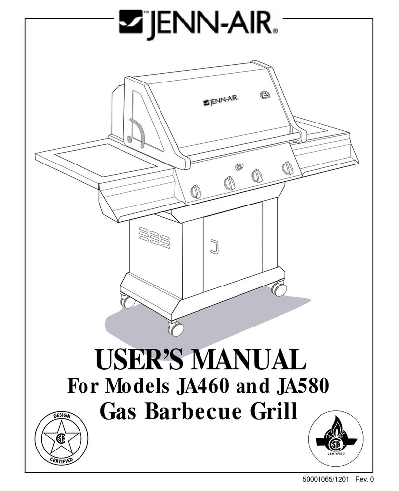
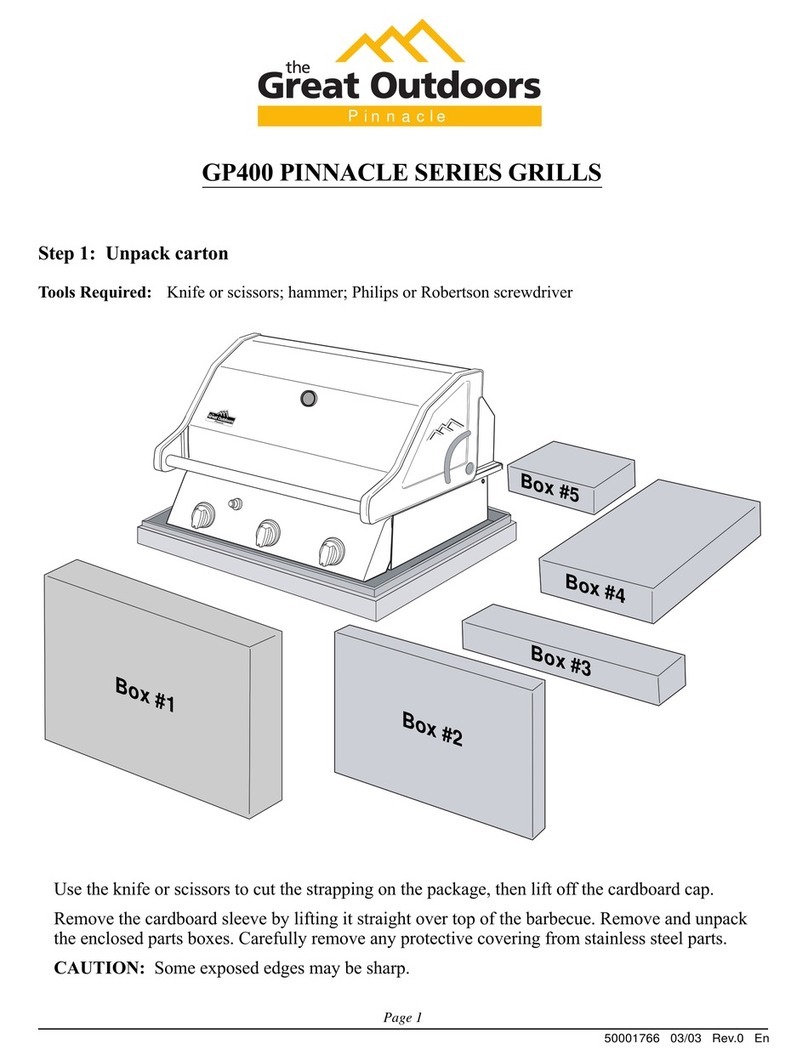
CFM BLACKSTONE 1000 User manual

®
CFM Corporation
Formerly: Now:

Congratulations and thank you for your purchase
of your new Great Outdoors grill. We are pleased
that you have recognized the value of the design,
function, and quality of components used in this
product. We believe it is among the nest on the
market.
We are committed to producing quality products
that your family will enjoy for years to come. If or
any reason we have failed to meet or exceed your
expectations, please allow us the opportunity to
make it right by calling us toll-free:
between the hours of 8:00 a.m. and 5:00 p.m.
Eastern Standard time, Monday through Friday.
We want you to be completely satised with your purchase
1-800-668-5323
Statement of Commitment
CFM Corporation
2695 Meadowvale Boulevard
Mississauga, Ontario L5N 8A3 Canada
(800) 668-5323
www.cfmcorp.com
Service Note: If you are experiencing difficulties or are dissatisfied with your purchase, please contact CFM at
the telephone number listed above prior to returning your grill to the store.
®
Formerly:
Now:

Teem oFCoNTENTS
F\ CxnprcR
Orue
- INSTALLATION
CHOOSING
ASAFE
LOCATION
Cxeprgn
Two
- PORTABLEGAS
GRILLBASICS
FUEL
FUELSUPPLYSYSTEM
FUELREGULATORANDHOSE
FUELCYLINDERSPECIFICATIONS
TRANSPORTINGAFULL
CYLINDER
TAKE
THESEINSTRUCTIONS
TOTHE
L.P.GASDEALER
FILLINGandPURGINGTYPE
1L.P.cAS CYLINDERS
PURGING
andEVACUATIONDEVICES
CrlprER
Txnee
-ASSEMBLYINSTRUCTIONS
INSTALLING
THE
GASSUPPLYCYLINDER
GnnpreRFoun
- LEAK
TESTING
Howro Cnecx
rHeFuEr-Suppl SysremronGnsLexs
Cnrpren
Fve
- OPERATING
YOUR
NEWGRILL
IGNITOR
LIGHTINGSYSTEM
LIGHTING
INSTRUCTIONS
MATCH
LIGHTING
HOWTOSHUTOFFTHEGRILL
CONTROL
SETTINGS
GxapreRSx - USINGtheGRILL
BREAKING
INANEW
GRILL
BURNER'S
FLAME
COOKING
withYOURNEWGRILL
IN
CASE
OFAMAJORGREASEFIRE,
DUALBURNERCOOKINGSYSTEM
STORINGan
L.P.
GRILL
Cxapren
SeveH
-CARE
ANDMAINTENANCE
CARING
FOR
YOUR
BARBECUE
GRILL
REGULAR
CLEANINGandUPKEEP
CLEANING
THEVENTURITUBES
ANNUAL
CLEANINGand
MAINTENANCE
OPTIONAL
ELECTRICAL
ACCESSORIES
Guapren
Erenr
- CONNECTINGTO NATURAL
GAS
(for
specially
equippednatural
gasgrills
only)
GHaprEn
NrHe
- REPLACEMENTPARTS
/ LimitedWarrantv
3
5
-7
I -22
20
24-25
26-27
28
-29
c
5
5
5
o
7
7
7
.&
23
23
24
24
25
25
25
26
26
26
27
27
27
28
28
28
29
29
30
F-!. 31
-32

CHapren
OHe
- INSTALLATION
lf
these
instructions
are
ignored,
thereisa
possibility
of
ahazardous
fireorexplosion
which
could
result
in
physical
injuryor
prop-
erty
damage!
ltis
your
responsibility
toas-
semble,
operate
and
maintain
your
gasgrill
properly.
CHOOSING
ASAFE
LOCATION
Once
you
have
assembled
your
new
grill,
findasuitable
location
foruse.Hereare
some
rules
to
follow:
1.This
gas
barbecue
grill
isforoutdoor
cooking
use
onlY.
Do
Not
use
in
garages,
breezeways,
sheds
or
any
enclosed
area.
Neveroperate
the
grill
inenclosed
areas
as
thiscould
leadtoa
carbon
monoxide
buildup
whichcould
result
in
injury
or
death.
2.lnstallation
nrust
conform
with
local
codes
or,
inthe
absence
of
localcodes,
with
either
the
National
FuelGasCode,
ANSI
2223.1,
NFPA
54
(USA),
orCAN/
CGA-B
149.2,
Propane
lnstallation
Code
(Canada)and
CAN/CGA-B
149.1Natural
Gas
Installation
Code.
Tocheck
localcodes;
contact
your
local
LP
gas
dealer
or
gas
company
listed
inthe
Yellow
Pages
forrec-
ommended
installation
procedures
and
regulations.
This
appliance
isnot
intended
tobe
installed
inor
onarecreational
vehicle
and/orboat.
3.
Locate
thebarbecue
away
fromany
combustible
construction
byat
least24
inches
(61
cm).
Do
notlocate
thebarbecue
grill
under
aceiling
orcover.
Heat
fromthe
grill
could
cause
damage.
Place
the
grill
on
alevel
surface.
The
grill
will
operate
best
ifitis
notfacingdirectly
into
the
wind.
Avoid
moving
the
grill
while
itisin
use.
4.
The
grill
area
must
be
clear
and
free
from
combustible
materials,
spare
LP
cyl-
inders,
gasolineand
other
flammable
liquids
or
vapors.
Donot
use
lighter
fluid
or
char-
coal
briquettes
inagas
grill.
Keep
the
ventillation
openings
of
thecylinder
enclo-
sure
free
and
clear
from
other
debris.
The
flow
ofcombustion
and
ventillation
air
is
not
tobe
obstructed.
5.
Place
your
grill
in
alocation
away
from
children
and
pets.
Do
notleave
the
grill
un-
attended
while
itis
in
use.Keep
children
and
pets
away
from
hot
grill.
NOT
FOR
USE
BY
CHILDREN.
WARNING:
Never
use
Natural
Gas
inaunit
designed
for
Liquid
Propane
(L.P.)
Gas.
Never
use
Liquid
Propane
(L.P.)
Gas
in
a
unit
designed
for
Natural
Gas.
WARNING:
The
outside
ofthe
barbecue
grill
body
will
become
hot
during
use'
To
avoid
burns;
do
not
touch
any
hot
grill
sur-
face.
lfnecessary,
use
aprotective
glove
when
operating
control
knobs,
tank
shut-off
valve
or
lidhandle.
Do
not
lean
on
or
place
over
15
pounds
on
a
side
table.
e,
@
I
a
o

Cnepren
Two
- PORTABLE
GASGRILLBASICS
BFUEL
Thisappliance
is
designedtouseLiquid
Propane
gas
(abbreviated
LP
gas
or
pro-
pane).
LP
gas
is
highlyflammable.
ltbe-
comes
liquidwhen
storedunderhigh
pres-
sureinsideacylinder
and
vaporizes
when
released.
LP
gas
isheavier
thanair
and
tendstocollectinlowareas.ltis
important
thattherearenoleakingconnections
on
yourgasgrill
that
couldcauseafire
orex-
plosion.
Refer
to
the
sectionlaterin
this
manual
on
"Testing
for
Gas
Leaks".
FUELSUPPLY
SYSTEM
Your
LP
gasgrill
requires
afuel
delivery
sys-
tem
whichis
madeupofaLP
gas
supply
cylinder,
afuelregulator,
hoseand
gas
con-
trol
valve.
Thefuelregulatorof
your
newbarbecue
grill
isequipped
with
a
Type
1couplingnut.
Do
Notattempt
toconnecttoany
otherLPcylin-
dernotequipped
with
amatingType
1cylin-
dervalve.This
grill
isnotto
beusedwith
any
othercylinderconnection
device.
FUEL
REGULATORAND
HOSE
The
pressure
regulator
andhose
assembly
withtheType1fittingsuppliedmustbe
used
withtheappliance.
Do
notuseanother
hose
andregulatorassemblyotherthanthe
one
supplied
withthe
grill
oramanufacturer's
re-
placement
pressure
regulator
assembly.
TheType
1connectionsystem
hasthefol-
lowingfeatures:
1.Thesystemwillnotallow
gas
toflow
until
apositive
connectionhasbeen
made.
2.Thesystem
has
a
thermal
elementthat
willshut-off
theflowof
gas
between2400F
and3000
F.
3.
The
system
hasaflowlimiting
device
which,
whenactivated,
willlimit
theflow
of
gas
to10cubic
feet
per
hour.
4.The
pressure
regulatorandhoseassem-
bly
provided
isfactorysetatanoutlet
pres-
sureof
11incheswatercolumn
(.4
lb.
per
sq.inch).
WARNING:Any
attempt
toadjusttheregula-
toris
dangerous
andcould
createasituation
causing
personal
injury
or
property
damage.
Consult
your
LP
gas
dealerif
you
think
the
regulatorisnotworking
properly.
FUELCYLINDER
SPECIFICATIONS
Any
LP
gas
supplycylinderused
with
this
grill
mustbeapproximately12
inches
diam-
eter
and18inches
high.Themaximum
fuel
capacitymust
be20
pounds
ofPropane.
Fullcylinder
weight
should
beapproximately
38
pounds(43.7
lbs.nominalwatercapac-
itv).
TheLPcylinder
musthaveashut-offvalve
terminating
in
aType
1LP
gas
cylinder
valve
outlet.
AType
1
compatiblecylinder
with
aType1cylindervalve
has
apositive
seatingconnection
whichdoes
not
permit
gas
flow,untilapositive
seal
has
been
ob-
tained.
DANGER:DoNotinsertanyforeignobjects
intothevalveoutlet.
Youmaydamage
the
backcheck.
Adamagedback
checkcan
cause
aleak,
whichcouldresultinexplo-
sion,fire,severe
personal
injuryordeath.
The
cylinder
must
bearrangedfor
vapor
withdrawal.ltmustalso
includeacollarto
protect
thecylinder
valve.Asafety
reliefde-
vicehaving
directcommunication
withthe
vapor
spaceofcylindermustbe
provided.
Thiswill
expel
high
pressuregas
ifthecylin-
der
is
overfilled
oroverheated.
AllLP
gas
cylinders
usedwiththis
appliance
shallbeconstructed
andmarked
inaccor-
dancewith
thespecifications
forLP
gas
cyl-
indersoftheU.S.
DepartmentofTransporta
@
F

tion
(DOT)
orthe
National
Standard
of
Canada,
CAN/CSA-8339,Cylinders
,
Spheres
andTubes
forTransportation
of
Dangerous
Goods;
and
Commission,asap-
plicable;
and
shallbe
provided
with
alisted
overfilling
prevention
device.
Readlabelson
the
LPGas
SupplyCylinder.
New
cylinders
arealways
shippedempty
forsafety.
Allowonly
qualified
LP
gas
deal-
ers
to
fillorrepair
your
LP
gas
supply
cylin-
der.
Inform
the
gas
dealer
ifitis
aneworused
cylinder
to
befilled.
Caution
the
gas
dealernotto
overfillthe
fuel
cylinder.
After
filling,
havethe
gas
dealercheckfor
leaks
and
toseethatthereliefvalvere-
mains
free
tofunction.
Havethe
gas
dealer
weigh
cylinder
afterfill-
ingtoensure
thatthecylinderisnotover-
filled.
TRANSPORTING
AFULLCYLINDER
WARNING!
Handle
afullcylinderwith
care.
Gas
isunder
high
pressure.
You
should
transportonlyonecylinder
at
a
time.
Transport
thecylinderin
anupright
andsecure
manner
withcontrolvalve
turned
off
and
the
POL
plug
in
place.
DoNot
transport
cylinder
in
passenger
com-
partment
of
a
vehicle,
DoNot
leavecylinder
indirectsunlightorin
ahigh
heatareasuch
asaclosedcartrunk.
High
heatareas
could
causethe
relief
valve
to
vent
gas.
DoNot
store
cylinder
in
abuilding,
garage
orany
other
enclosed
area.
Store
outdoors
inawell
ventilated
area,awayfrom
people
and
outof
thereach
of
children.
Use
acylinder
capon
cylindervalve
outlet
during
transport
and
whenthecylinder
is
not
connected
to
grill.
Keepcylinder
valve
closed
when
notin
use.
WARNING!
Do
notstore
aspare
LP-gascylinder
under
ornear
thisappliance.
Never
fill
thecylinder
beyond
80
percent
full.
lfthis
information
isnot
followedexactly,
a
firecausing
deathor
serious
injurymay
occur.
a
^4.
DualBurnerFuelControlValve
I
I
Cylinder
Control
Valve
L.P.Gas
Cylinder
Type
1Fuel
Regulator ValveOrifice
FuelSupply
Hose
TheFuelSupplySystem
consisfrng
offuelcontrolvalve
withhose
and
regulaforassembly
andL.P.gascylinder
6

*
TAKE
THESE
INSTRUCTIONSTO
THELP
GAS
DEALER.
When
using
acylinderexchange
besurethe
exchanged
cylinder
is
aType
1cylinder,as
a510
POL
cylinder
willnotfitType1regula-
tor.
FILLING
andPURGING
TYPE
1LPGAS
CYLINDERS
DANGER!
Purgingand
filling
ofLPGascyl-
inders
mustbe
per{ormed
by
personnel
who
have
been
thoroughlytrainedinaccepted
LPGas
industry
procedures.
Failuretofol-
lowthis
instruction
mayresult
in
explosion,
fire,
severe
personal
injury,or
death.
IMPORTANT
Purgenewcylindersbefore
filling.
Thistank
iseasilyfilledwithastan-
dardCGA
510
POLfillingconnection.
TheLPGas
cylinderhasa
Type1
cylinder
valve
withaback-check
moduleinits
outlet
whichwillnot
permitgas
toflowuntilan
evacuation
device
is
installed.
To
purge
the
LPGas
cylinder,
thebackcheckmodule
must
beopened
with
anevacuationdevice.
PURGING
and
EVACUATION
DEVIGESfor
LPGAS
CYLINDERS
withryPE 1GYLIN-
DER
VALVES
A.
Hose
endvalve
withableed
port:
Purging
can
beaccomplished
using
a
hose
end
valvecontaining
ableed
port
whichalsoal-
lows
forevacuation
without
theuseofan
adapter.
B.Hose
end
valve
withoutableed
port:
Whenahose
end
valvedoesnot
havea
bleed
port,
aseparate
device
mustbeused
forevacuation.
C.
Purgingusing
a
Type1connection:
LP-
Gas
cylinder
evacuation
canbeaccom-
plished
during
each
purging
byusing
aType
1connection.
TheType
1valveoutlet
has
anexternal
I 5116"
ACMEright
handthread
which
willaccept
thisconnection.
CAUTION:After
purging
orfilling
anLPGas
cylinder,
DoNot
insert
aPOL
plug
intothe
valveoutlet.
Insertion
of
this
plug
will
pre-
ventthe
back-check
from
closing.Use
ONLY
the
provided
cap
andstrapattached
totheoutlet.
Close
the
cylindervalve
knob
before
returning
thecylinder
tothe
cus-
tomer.
For
proper
purging
procedures
intheU.S.A.
refer
to:Safety
Bulletin
NPGA# 133,
"Purg-
ing
LP-Gas
Cylinders,"
and
Safety
Bulletin
NPGA# 130,
"Recommended
Procedures
forFilling
Cylinders".
r-
w4'
F
\..
CGA.slOPOL
Filling
a
Type1
Cylinder
Valve
Twoexamples;
The
top
drawing
shows
using
aCGA-510
POLfitting.Theright
drawing
shor,vs
usinga Type1POLfitting.
TYPE1

Csapren
THnEe
-ASSEMBLY
INSTRUCTIONS
tools
needed
toassemble
grill:
a 318"
open
end
wrench
aflat
blade
screwdriver
aT116"
open
end
wrench
HINT
a socket
sef
oran
adiustable
wrench
mayalso
beused.
Assembly
Step
1.
Unpack
Grill
Parts.
1. Remove
and
set
aside
all
innerboxes
and
parts
from
the
master
carton.
2. Remove
and
set
aside
all
wrapping
paper
and
additional
packaging
fromthe
parts.
3. Do
not
destroy
carton
or
packing
until
your
grill
iscompletely-assembled
and
bperaling
to
your
satisfaction.
Main
bag
containg:
1) hardware
bag
"A",
1) hardware
bag
"B",
1) hardware
bag
"C",
1) hardware
bag
"D"
pillar
(1)
base
(1)
Getting
Started;
1.Please
follow
the
steps
intheorder
that
they
are
presented.
2.
Assemble
the
grill
atthe
location
that
you
intend
to
use
it.
3.
You
may
want
toplace
anoldtowel
or
cloth
atthe
assembly
site
toprevent
scratches
to
your
deck
and/or
to
prevent
nuts
and
bolts
frombecoming
lost.
4.Have
a
friend
help.
While
theunit
ismade
oflightweight
aluminum,
there
isa.lotof
it!
An
assistaht
can
makethe
assembly
easier,
by
holding
the
parts
in
place
while
fastening
thenuts
and
bolts
in
Place.
5.
Your
barbecue
has
been
provided
witha
Liquid
Propane
(L.P.)
gas
cylinder.
As
stated
beiore,
itis
shipped
empty
forsafety
reasons.
In
order
tobe
ready
tobarbecue
immediately,
please
have
your
fuelcylinder
filled
with
L.P.
gas
by
anauthorized
L.P.
gas
dealer.
a
f
A
U]

grill
bottom
casting
(1)
handle
(1)
handle
standoff
(21
standoff
gasket \m
m
(2)
grill
lid
(1)
rock-grate
(1)
ceramrc
briquettes
(1
bag)
.Iq
Y
side
tables
(2)
cooking
grids
(2 piece
)
warming
rack
(1)
L.P.
gas
cylinder
(1)
heatshield
(1)
grease
pan
(1)
N
2 cYlinder
/ . retainer
\ )) wire
\/ (1)
\z'

I
toolsneeded:
a318"openend
wrench
a7l16"
openend
wrench
base
(1)
tl
\{
pillar
(1)
AssernblyStep
2.
AttachthePillar
totheBase.
Lockthe
pre-assembled
casters
on
base
by
pushing
downon
the
latch.
,iffi (Th.is
symbolis
tohelp
lr'ffiJ orient
areaof
assembly.)
hardware
bag
"A"
containing:
f

r
F
f,
2. Positionthe
pillar
upside-down
and
setthebaseontothe
pillar
as
shown.
Working
fromtheopensideof
pillar:
3. Insertboltsthroughthetwoslots
atthe
frontofthe
pillar
and
through
theholesinthe
frontof
thebase.
Threadnutsontobolts.
Alignrear
holesandinsertbolts.
Add
nutsandusewrenchesto
tighten.
4. Carefully
turntheassembly
upright.
5. Check
the
pre-assembled
control
valvelocatedinsidethe
pillar.
lfit
has
plastic
capscoveringthe
back
valveorifices,the
plastic
caps
willneedtoberemoved
. now.
Remove
the
plastic
film
covering
thefrontofthecontrol
panel
plate.

I
Assembty
Step
3.
Attach
theGrill
Bottom
to
thePillar.
A
4ffi
R.????
Ft n\
\J\
-&\
w
w \
t;
fools needed:
a3/B"open
endwrench
a7l16"
openend
wrench
f
Position
the
grill
bottom
onto
the
pillar
so
that
the
rear
hingestruts
are
toward
the
open
side
of
the
pillar,
asshown.
Four
holes
in
thebottom
will
align
with
two
rear
holes
and
two
front
slots
in
the
pillar.
I
I
I
l
I
!
!
I
I
J
J
I
I
I
J
!
l\
\\
t\
ffi
<5::<
>L1:D
{:5:-.d
A*I}R
€r<
€5j<
4-5tZ
?,F.4
*."i5
ffi'|
_a
T:U'
14-20x1"
(4)
s
v

r_l-ril_ \UJ
3. IMPORTANT:Makesurethe
control 5. Locate
thetwoblack
leadwires
valveendsareinsidetheburner
tubes beneath
the
qrill
bottom.Pressthe
extending
through
the
grill
bottom. looseendsoithe
leadwiresonto
the
metaltabs
locatedon
thebackofthe
4. Insertfourboltsintothebottom'sholes igniterunit.
and
securewithnuts.
r

Assembly
Step
4.
Attach
SideTables
totheGrill
Bottom.
a3/B"
open
end
wrench
a7116"openendwrench qj
(9..
q,
eb
1.
2.
Insert3/4"boltsthroughholes
inthe
supportarms
ofthesidetables,
as
shown.
Slide
agasket
washeroverthe
threadedend
ofthebolt.
NOTE:
The
gasket
washersareintended
tofit
tightlyonthe
boltssoas
toholdthe
bolts
in
place
whileattaching
theside
table
tothe
grill.
Prepareboth
sidetables
in
this
manner;using
fourboltsand
gasket
washers
foreachtable.
3.
hardware
bag
"C"
containing:

4. Attach
thesidetabletothefour
holes
located
inthe
side
ofthe
grill
bottom
using
the
locking
hexnuts
provided.
Attach
theoppositesidetable
inthe
samemanner.
(.\*i\
$:-i-;]x\
.F

Assembly
Step
5. the
Grill
Lid
Assembly
hardware
bag
"D"
containing:
A hair
pin tl
\:-\Az (2') | I
ffi lt
@@r,
\7 e hinge
pin
114-20
x5/8" 114-20 '|14x1118"
(4) (4) (21
Position
thebackof
thelidsothat
the
rearholesare
in
line
withthe
hinge
struts
on
theback
ofthe
grill
bottom.
Gently
setthe
grill
lidonto
the
grill
bottom.
fools needed:
a7l16"
open
endwrench
aflat
blade
screwdriver

?
3.
4.
Hold
thelid
toalign
thehingeholes.
Insefi
ahinge
pin
throughthehinge
hole
in
thelidand
into
theholein
the
bottom
hingestrut.
Afterthe
hinge
pin
isin
place,
inserta
hair
pin
through
thehole
ofthehinge
pin
tosecureit.
HINT
There
isan
airspacebetween
the
backofthe
lidandthe
grill
bottom
where
you
can
installthe
pins.
Repeat
forthe
oppositeside.
@
-E€ 5.
\" 4.
\
5.b
?h
r
/
I
I
I
,
I
I
\\\\
k-
\I
i 'j'
/-;\:
\v/-;S\
\\7l
\./
\--l
1.Raise
the
lidtoattachthefront
handle.
Attachahandlestandoff
tothe
front
ofthe
grill
lid,asshown.
lnsert
one
endofthehandleintothe
hole
ofthe
standoff.
Whileholding
thehandlein
place
assemble
theoppositestandoffto
the
lid
inthe
same
manner.
2.
3.
4.

no tools
needed
rock-grate
(1)
ceramic
briquettes
(1bag)
Assernbly
Step
6. Installing
the
Internal
Components
in
the
Grill.
N
Place
the
single
rock-grate
into
the
grill
bottom.
K\.\\."N

?2. Open
the
package
containingthe
ceramic
briquettes.
3. ltis
importantto
properly
arrangethem
onto
the
rock-gratetoallowfor
good
air
flowduringuse.
NOTICETHESPACING:
The
proper
amountofbriquettesare
supplied
andthereisno
needtoadd
more.
Somespacebetweenthe
b
ri
q
u
ette
slsnecessary.
,'F.'-Ff
Setthe
twocooking
grids
onthefront
and
back
ledgesformedinside
the
grill
bottom
foralevelcookingsurface.
"F
s
NN
Setthe
warming
rackontotheback
ofthe
cooking
grids.
4.

Assembly
Step
7. Installing
the
Gas
SuPPIY
Cylinder.
Gonnecting
the
Regulator
toGylinder
coupling
nut
connects
to
the
large
outside
threads
on
the
valve
outlet'
Use
care
not
to
cross-thread
the
connection.
5.
Handtighten
the
coupling
nut
clockwise
and
tighten
until
itcomes
to
a
full
stop'
Tighten
by
hand
only.
Do
Not
use
tools'
6.
CAUTION:
In
the
connection
process,
the
grillside
of
the
connection
will
seal
onthe
6ack-check
in
the
valve,
resulting
in
aslight
resistance.
The
connection
requires
about
one-half
to
three
quartersadditional
turn
to
complete
the
connection.
NOTE:
lf
you
cannot
complete
the
final
con-
nection,
disconnect
the
regulator
and
repeat
steps
4through
6.lf
you
are
still
unable
to
complete
the
connection,
do
not
use
this
valve
and
regulator.
7.
Make
sure
the
hose
has
no
kinks
or
sharp
bends
and
clears
any
areas
that
will
become
hot
during
use.
Never
put
strain
on
the
hose
where
it
joins
a
fitting.
The
rubber
fuel
sup-
ply
hose
must
not
touch
the
bottom
grill
casting
during
use.
8.
Before
lighting
grill,
check
all
connections
''--
for
leaks
using
amild
soapy
water
solution'
20
WARNING:
Connect
the
LP
cylinder
to
the
grill
outdoors
onlY.
F,ead
and
follow
all
directions
on
the
cylin-
der
and
fuel
hose
safetY
tags.
1.
The
top
knob
on
the
supply
cylinder
must
be
closed.
See
that
the
top
cylinder
knob
is
turned
clockwise
toafull
stoP.
2.
Check
that
all
the
grill
burner
knobs
are
turned
tooff'
3.
Remove
the
protectivecaps
from
the
cyl-
inder
valve
and
coupling
nut,
if
present.
4.
Hold
the
regulator
inone
handand
insert
the
nipple
into
the
valve
outlet.
Be
sure
the
nipple
is
centered
in
the
valveoutlet.
The
L.P.
gas
cylinder
(1)
Table of contents
Other CFM Grill manuals
Popular Grill manuals by other brands

hestan
hestan GABR Series Use & care manual

Heinner
Heinner HEPG-F2000BKSS instruction manual

COUNTRY SMOKERS
COUNTRY SMOKERS CS1374 Assembly & operation

cecotec
cecotec Rock'nGrill 750 Full Open instruction manual

Brice
Brice FAMPDR3000 Brochure & Operating Manual

Breville
Breville Gourmet Health Grill TG400XL Instructions for use and recipe book