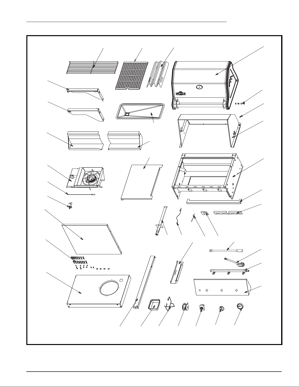
CFM GP400 PINNACLE Series User manual

Page 1
GP400 ASSEMBLY
GP400 PINNACLE SERIES GRILLS
Step 1: Unpack carton
Tools Required: Knife or scissors; hammer; Philips or Robertson screwdriver
Use the knife or scissors to cut the strapping on the package, then lift off the cardboard cap.
Remove the cardboard sleeve by lifting it straight over top of the barbecue. Remove and unpack
the enclosed parts boxes. Carefully remove any protective covering from stainless steel parts.
CAUTION: Some exposed edges may be sharp.
Box #2
Box #5
Box #4
Box #3
Box #1
50001766 03/03 Rev.0 En
PinnaclePinnacle

Page 2
GP400 ASSEMBLY
Step 2: Position main grill head.
Required: Main Grill Unit.
Carefully lay the main grill unit on its back, using
the flattened carton cap as a protective surface.
This operation is best performed by two (2) people.
Use of gloves is recommended.
Ensure the front lid does not fall open while moving
the unit.
Allow the lid to rest partially open once the unit is on
its back (Fig. 2).
Fig. 2
Fig. 3
Step 3: Assemble legs to bottom panel.
Required: (4) legs; the Bottom Panel; (8) 1/4-20 x 1 1/2”
bolts
Assemble the four (4) legs to the bottom panel as shown,
with two (2) bolts each. Tighten fully (Fig. 3).

Page 3
GP400 ASSEMBLY
Step 4: Assemble Legs to Grill Unit
Required: (8) 1/4-20 x 1 1/2” bolts
Position the leg assembly into the base unit
until the two round bolt holes align with the
thread inserts in the legs, as shown. Ensure
the tank hole (on LP models) is at the right
hand end of the grill. Assemble with two (2)
bolts per leg, leaving the bolts loose by 3 or
4 threads. See Fig. 4.
Caster
Locking Tab on
each caster to be
in "down" position.
Fig. 4
Fig. 5
Step 5: Assemble Casters
Required: (4) Casters
Push a caster into the bottom of each leg as far as possible.
Ensure the casters are locked; i.e., the locking tabs are in
the “down” position, as shown.
Carefully stand the grill upright while securing the front
lid from falling closed. Again, two people are recom-
mended for performing this.
Step 6: Install Front Panel
Required: the Front Panel; (4) Plastic Push-pins
Position the Front Panel between the front grill legs, aligning
the two (2) holes in the side flanges of the panel with those
in the legs. Push a pin into each hole as far as possible. It
may be necessary to lightly tap the pins.
See Fig. 6.
Fig. 6. (Back view of grill)
(Push-pin)

Page 4
GP400 ASSEMBLY
Step 7: Install Grease Cup, Cup Holder,
and Pan.
Required: Grease pan, grease cup and grease
cup holder
Assemble the cup holder into grease pan opening
by squeezing the ends in slightly, then releasing.
Place a grease cup into the holder, as shown in
Fig. 7a.
Position the grease pan into the back side of the
grill just below the back panel—with the grease
cup at the right end—on the two (2) support rails.
Push the pan in squarely until it settles into the
recesses of the supports (Fig. 7b).
Step 8: Assemble side shelf brackets
Required: (2) right shelf brackets, (2) left shelf
brackets, (4) spring clips
Push a spring clip over the underside end hole
in each bracket, as shown (Figs. 8a and 8b).
Attach a right and a left bracket over the leg
attachment bolts, then push the brackets down
fully (Fig. 8c). Tighten the four (4) bolts fully
(Fig. 8d).
Repeat on the other side.
Fig. 8d
Fig. 8a
Fig. 8b
Fig. 8c
Fig. 7a
Fig. 7b

Page 5
GP400 ASSEMBLY
Step 9: Assemble side shelves.
Required: (2) side shelves; (1) left and (1) right
front shelf; (6) #10-24 x
1
/
2
” bolts;
(2) #10 locknuts
Hook the left and right front shelves over the
corresponding front shelf supports, and push them
toward the grill base. Attach to the bottom of the
control console with (1) bolt and (1) nut each
(Fig. 9a).
Assemble the side shelves to the brackets by posi-
tioning them halfway over the brackets, then sliding
them towards the grill while pushing down firmly
on the front edge. The slots at the front edge of the
shelves should align with the tabs at the back of the
shelf supports (Fig. 9b).
NOTE: On models with Side Burners, assemble the
shelf with the open center to the right-hand side of
the grill. After completing this step, follow the
instructions in the Side Burner Kit.
Tap the shelf lightly, if necessary, to fully engage
the slot and tab. Once aligned, fasten with a bolt
through the spring clips (Fig. 9c).
Fig. 9c
Fig. 9b
2
1
Fig. 9a
(2) #10-24 Locknut
(6) #10-24 x
1
/
2
” Bolt
Slot
Tab
View rotated
90 degrees

Page 6
GP400 ASSEMBLY
Step 10: Install Internal Components
Required: (3) sear plates, (2) cooking grates,
warming rack
Refer to Fig. 10.
Place the sear plates into the base unit ensuring that edges
with the finger holes face the grill front, and the side
edges face down.
Position the cooking grates into the base similarly; these
may be turned over to provide a flat surface for delicate
foods.
Set the warming rack into the two supports in the ends of
the rear lid.
Step 11: Install the LP cylinder
(LP models only)
Required: LP gas cylinder (not supplied)
NOTE: Before lighting the grill, refer to the
owner’s manual for proper cylinder
specifications, filling requirements,
regulator attachment and leak testing
procedures.
Sear Plates
Cooking
Grates
Warming
Rack
Finger
Hole
Fig. 10
Fig. 11

Page 7
GP400 ASSEMBLY
4
24
22
214
15
31
38
33
1
10
13
16
17
11
12
26 259
3
37
30
8
36
32
35 19
34
5
29
28
27
6
18
21
20
23 7
GP400

GP400
Ref. Description Qty GP400
1 Panel Bottom H3 Assembly 1 50001310
2 Leg H3 – Final Assembly 4 50001317
3a Front Panel H3 – Charcoal 1 50001290
3b Front Panel H3 – S/S 1 50001667
4 Caster 4 50000090
5 Base Assem H3 1 50001462
6 Lid Assembly, Rear Black H3 1 50001279
7a Lid Assembly, Front – GP3xx1 – Charcoal 1 50001698
7b Lid Assembly, Front – S/S 1 50001699
8 Flash Tube – H3 1 50001300
9 Support, Grease Pan 2 50001302
10 Burner, Main, Assembly – HBQ 3 50000835
11 Gasket Burner – HBQ 3 50000892
12a Valve Assembly – H3 – Natural 1 50001439
12b Valve Assembly – H3 – Propane 1 50001438
13 Console Assembly – H3 – GP3251A 1 50001669
14 Bezel 3 50001327
15 Knob – H3 3 50001455
16a Regulator – H3 1 50001308
16b Regulator – Side Burner 1 50001678
17 12’ Natural Gas Hose 1 50000198
18 Hardware, Lid Set 1 50000355
19 Grease Pan H3 1 50001301
20 Cook Grates– H3 Enamel 2 50001314
21a Plate Heat - H S/S 3 50000777
21b Plate Heat – Enamel 3 50000877
22 Grease Cup 1 50000126
23 Warming Rack–- H3 Enamel 1 50001311
24 Grease Cup Holder – H3 1 50001319
25 Electrode, Main – Short 1 50000431
26 Electrode, Main – Long 2 50000523
27 Lid Bumpers 4 50000177
28 Support, Shelf, Left – Black – H/VC 2 50001418
29 Support, Shelf, Right – Black – H/VC 2 50001419
30 Front Lip – H3 1 50001482
31 Ignitor Kit – H4 1 50000816
32a Shelf, Top, Solid – H – S/S
*
50001413
32b Shelf, Side, Open – H – S/S
*
50001412
32c Shelf, Top, Solid – Black
*
50001703
32d Shelf, Side, Open – Black
*
50000824
33 Hardware Bag - H3 1 50001390
34 Shelf, Front, Right – HL 1 50000984
35 Shelf, Front, Left – HL 1 50000986
36a Side Burner – Electric – Black – W/G 1 50001648
36b Side Burner – Rotiary – Black – C/G 1 50001649
36c Side Burner – Electric – Black – C/G 1 50001660
37a Valve, Side Burner – H – Propane 1 50001046
37b Valve, Side Burner – H – Natural 1 50001045
38 Wire Connector 33 S/B 1 50001668
*
Varies by model
CFM Harris Systems • 3501 W. Howard Street • Skokie, IL 60076-4012 USA • Phone: (800) 944-8982 • Fax: (847) 676-3759
GP400 ASSEMBLY
Table of contents
Other CFM Grill manuals