CGC RYAN JR SODCUTTER 544844E User manual

OPERATOR’S MANUAL
MAN 4163212
Rev. A 10-2007
MODELS:
MODELOS:
MODèLES:
MODELLS:
544844E
544845E
544944A
544945A
JR SODCUTTER
GB E NL F S D
MANUAL DE OPERACIÓN Y SEGURIDAD
GERBUIKSHANLEIDING
MANUEL D’UTILISATION ET DE SÉCURITÉ
INSTRUKTIONSHANDBOK
BEDIENUNGSHANDBUCH

CALIFORNIA
Proposition 65 Warning
Diesel engine exhaust and some of
its constituents are known to the State
of California to cause cancer, birth
defects and other reproductive harm.
Californie Proposition 65
Avertissement
Les échappements des moteurs diesel
et certains de leurs composés sont
reconnus par l’Etat de Californie pour
être cancérigènes, provoquer des
défauts congénitaux et d’autres dangers
en matière de reproduction.
ADVERTENCIA
AVERTISSEMENT
WARNING
The engine exhaust from this product
contains chemicals known to the State
of California to cause cancer, birth
defects or other reproductive harm.
California Advertencia
de la Proposicion 65
El estado de California hace saber que
los gases de escape de los motores
diesel y algunos de sus componentes
producen cáncer, defectos de
nacimiento y otros daños en el
proceso de reproducción humana.
L’
é
mission du moteur de ce mat
é
riel
contient des produits chimiques que
l’Etat de Californie consid
è
re
ê
tre
canc
é
rig
è
nes, provoquer des d
é
fauts
cong
é
nitaux et d’autres dangers en
mati
è
re de reproduction.
El estado de California hace saber
que los gases de escape de este
producto contienen productos
quÍmicos que producen cáncer,
defectos de nacimiento y otros daños
en el proceso de reproducción
humana.
CALIFORNIA
Proposition 65 Warning
Battery posts, terminals, wiring
insulation, and related accessories
contain lead and lead compounds,
chemicals known to the State of
California to cause cancer and birth
defects or other reproductive harm.
WASH HANDS AFTER HANDLING.

GENERAL INFORMATION
IMPORTANT!
THIS MANUAL WILL AID YOU IN THE SAFE
OPERATION AND PROPER MAINTENANCE OF
YOUR EQUIPMENT. READ MANUAL THOROUGHLY
BEFORE ATTEMPTING OPERATION. IF ANY
PORTION IS NOT CLEARLY UNDERSTOOD,
CONTACT AN AUTHORIZED DEALER FOR
CLARIFICATION.
To make sure you are fully aware of safety and service
information, the following two symbols are used
throughout this manual.
!! This symbol is used throughout the manual to
alert you to information about unsafe actions or
situations, and will be followed by the word DANGER,
WARNING, or CAUTION. DANGER indicates
immediate hazards that will result in severe injury or
death. WARNING indicates unsafe actions or situations
that may cause severe injury, death and/or major
equipment or property damage. CAUTION indicates
unsafe actions or situations that may cause injury, and/or
minor equipment or property damage.
NOTICE This symbol appears next to
information or instructions which will help you operate
and maintain your equipment the right way.
WARNING
!
The information and instructions included in
this manual alert you to certain things you
should do very carefully. If you do not, you
could:
∗hurt yourself or others
∗hurt the next person who operates the
equipment
∗ damage the equipment.
This manual contains essential operation and
safety information and must remain with the unit
at all times, within easy access of any operator.
Additional manuals are available through your dealer.
IMPORTANT!
THIS EQUIPMENT SHOULD NOT BE MODIFIED OR
ADDED TO WITHOUT THE MANUFACTURER'S
AUTHORIZATION.
WARNING
!
Altering this equipment in any manner which
adversely affects the equipments operation,
performance, durability or use, may cause
hazardous conditions.
Direct any inquiries to:
One Bob-Cat Lane
P.O. Box 469
JohnsonCreek, WI 53038±0469 USA
SPECIFICATION INFORMATION
All information contained in this manual is the latest
available at the time of printing. Commercial Grounds
at any time without notice.
Whenever a name brand product is specified, an
equivalent product may be used unless stated otherwise.
CHANGE OF OWNERSHIP OR ADDRESS
Care, Inc. reserves the right to make changes
Your dealer has REGISTRATION CHANGE FORMS
which will be filled out and filed by the dealer for his
records, and a copy will be sent to the manufacturer.
1
Commercial Grounds Care, Inc.
Commercial Grounds Care, Inc. makes every effort to keep
owners informed of all safety related information. Therefore,
changes in ownership and/or address should be reported
to the manufacturer.

524541
This decal instructs the operator to read and understand the
operators manual. To prevent injury, they must be familiar
with the operation of this product and is fully aware of safe
operating procedures.
This decal informs the operator that hearing
protection should be worn if operating the Jr.
Sodcutter for extended periods of time (longer
than four hours).
This top symbol shows fingers or hands being cut or severed.
DO NOT place hands or fingers under Jr. Sodcutter while
operating the unit.
This middle symbol shows toes and feet being cut or severed.
DO NOT place feet or toes under Jr. Sodcutter while operating
the unit.
The symbols used in the lower part of the decal are used to
inform the operator and/or bystanders to keep a safe distance
away from machinery. If you do not keep hands and feet a safe
distance from the machinery, personal injury could occur.
PICTORIAL DECALS
The throttle control decal uses the turtle to represent
slower engine speeds, the rabbit represents faster
engine speeds.
This decal indicates the unit is certified for use for
the European community.
94
dB
94
dB
009034910
2

PICTORIAL DECALS
524485
524486
840697
The left symbol is used to
show the possible result of
working on machinery with
safety shields removed.
Hands and fingers may
become entangled in belts.
DO NOT operate the unit
without safety shields in
place.
The right symbols instruct
the operator to read the
service section of the
operators manual. Disable
the engine (disconnect
spark plug wire) before
performing any service or
maintenance on the unit.
The center symbols warns
the operator and/or
bystanders to keep hands
out of moving components.
This decal shows the direction of lever movement used to
engage the drive wheels of the Jr. Sodcutter. Movement in
opposite direction will stop drive wheels.
This decal shows the direction of lever movement used to
engage cutter blade. Movement in opposite direction will
stop the blade.
Direction of handle engagement.
Direction of handle engagement.
Push lever forward to engage drive belt.
Pull lever rearward to disengage drive belt.
3

EQUIPMENT IDENTIFICATION
544844E Jr. Sodcutter – 12 inch (305 mm). . . . . . . .
544845E Jr. Sodcutter – 18 inch (457 mm). . . . . . . .
544944A Jr. Sodcutter – 12 inch (305 mm). . . . . . . . .
544945A Jr. Sodcutter – 18 inch (457 mm). . . . . . . . .
INDEX
ADJUSTMENTS:
Blade angle 11. . . . . . . . . . . . . . . . . . . . . . . . . . . . . . .
Blade, depth adjustment 11. . . . . . . . . . . . . . . . . . . .
Operator presence switch 11. . . . . . . . . . . . . . . . . . .
EQUIPMENT IDENTIFICATION NUMBERS
Serial Number and Model Number plate 5. . . . . . .
GENERAL INFORMATION 1.. . . . .
OPERATION 10. . . . . . . . . . . . . . . . . . . . . . . . . . . . . . . . . .
Controls 9-10. . . . . . . . . . . . . . . . . . . . . . . . . . . . . . . . .
Cutting sod 12. . . . . . . . . . . . . . . . . . . . . . . . . . . . . . .
Daily maintenance checklist 10. . . . . . . . . . . . . . . . . .
Moving of unit 11. . . . . . . . . . . . . . . . . . . . . . . . . . . . .
Ownership change 1. . . . . . . . . .
Starting engine 11. . . . . . . . . . . . . . . . . . . . . . . . . . . .
Storage 12. . . . . . . . . . . . . . . . . . . . . . . . . . . . . . . . . .
Transporting unit 12. . . . . . . . . . . . . . . . . . . . . . . . . . .
SET–UP 5-9. . . . . . . . . . . . . . . . . . . . . . . . . . . . . . . . . . . .
SPECIFICATIONS
Pictorial decals 2–3. . . . . . . . . . . . . . . . . . . . . . . . . .
Sodcutter 4. . . . . . . . . . . . . . . . . . . . . . . . . . . . . . . . . .
Touch–up paint 4. . . . . . . . . . . . . . . . . . . . . . . . . . . . .
SPECIFICATIONS
MODELS: 544844E,, 544845E
Engine 4 cycle 6.5 H.P. B&S Vanguard,. . . . . . .
Model 12H332, Type 0115, Trim B8,
12.5 cu. in. (205 cc) w/recoil starter.
Governor set at 3600 ±100 rpm,
no load.
Noise Level Sound pressure level –88 dB(A). . .
(pressure based)
Sound power level – 99 dB(A)
(power based)
Vibration Handlebar vibration level in z–axis. . . . .
29.4 meters per second squared
Clutch Spring loaded belt tightener type.. . . . . . . .
Reduction Engine to blade 2.94:1. . . .
Engine to drive wheels 55.8:1
Wheels Drive: 8” (203 mm) dia. w/knobby. . . . . . .
tread vulcanized to hub.
Rear: 8 x 1.75 semi–pneumatic
w/pre–packed ball bearings.
Drive “A” section belt from engine to. . . . . . . . .
gear case, roller chain in gear
case to drive shaft and blade
drive.
Gear Case Lubrication: EP140 Gear Lube. . . .
Capacity: 3 1/2 Pints (1.7L)
Cutting width 11 3/4” (298 mm).
18” (457 mm)
Blade speed 1225 oscillations/min. at 3600 rpm. .
Blade pitch Hand lever adjustment, variable. . .
from 0 to 9 degrees
Weight269 lb. (122.1 Kg). . . . . . . .
327 lb. (148.5 Kg)
Dimensions Width: 24” (600 mm). . .
Height: 33” (838 mm)
Length: 49” (1,244 mm)
Wheelbase: 19” (483 mm)
Standards Conforms to European Community. . . .
(EC) standard 89/392 and amend–
ments 91/368 and 93/44. CARB, EPA.
MODELS: 544944A, 544945A
Engine 4 cycle 5.5 H.P. Honda GX160 OHV,. . . . . . .
Model GX160–K1QX2
9.9 cu. in. (163 cc) w/recoil starter.
Governor set at 3600 ±100 rpm,
no load.
Noise Level Sound pressure level –92 dB(A). . .
(pressure based)
Sound power level – 105 dB(A)
(power based)
Vibration Handlebar vibration level in z–axis. . . . .
32.4 meters per second squared
Clutch Spring loaded belt tightener type.. . . . . . . .
Reduction Engine to blade 2.94:1. . . .
Engine to drive wheels 55.8:1
Wheels Drive: 8” (203 mm) dia. w/knobby. . . . . . .
tread vulcanized to hub.
Rear: 8 x 1.75 semi–pneumatic
w/pre–packed ball bearings.
Drive “A” section belt from engine to. . . . . . . . .
gear case, roller chain in gear
case to drive shaft and blade
drive.
Gear Case Lubrication: EP140 Gear Lube. . . .
Capacity: 3 1/2 Pints (1.7L)
Cutting width 11 3/4” (298 mm).
18” (457 mm)
Blade speed 1225 oscillations/min. at 3600 rpm. .
Blade pitch Hand lever adjustment, variable. . .
from 0 to 9 degrees
Weight269 lb. (122.1 Kg). . . . . . . .
327 lb. (148.5 Kg)
Dimensions Width: 24” (600 mm). . .
Height: 33” (838 mm)
Length: 49” (1,244 mm)
Wheelbase: 19” (483 mm)
Standards Conforms to European Community. . . .
(EC) standard 89/392 and amend–
ments 91/368 and 93/44. CARB, EPA.
TOUCH–UP PAINT
Ransomes Green
16 oz. (0.5L) spray can, order Part No. 838140
1 qt. (0.95L) can, order Part No. 838141
4
SERIAL NUMBER
AND
MODEL NUMBER PLATE
The serial number and model number plate on the Jr.
Sodcutter is pictured below. The plate is located on top
the gearcase to the rear of the unit, just in front of the han-
dlebar mounting location.
SET±UP
WARNING
!
To prevent serious injury, ALWAYS wear eye
protection and stand clear when cutting band-
ing. Banding is under tension and may snap
back when cut.
NEVER disable the operator presence control by
altering or modifying it in any way.
The Sodcutter is very heavy, to prevent serious
injury, use an adequate lifting device (i.e., hoist,
fork lift, etc.) to remove from shipping pallet.
1. Remove and discard banding attaching Jr. Sodcutter
to pallet.
2. Remove and discard reinforced tape securing han-
dlebar and clutch control assembly to pallet.
3. Using an adequate lifting device, remove Jr. Sodcut-
ter from shipping pallet.
4. Remove hardware bag and empty contents onto a
surface where they will not be misplaced or lost.
5. Loosen, remove and retain hardware securing guard
to side of unit. Remove guard to allow access to idler
assembly and brake band components.
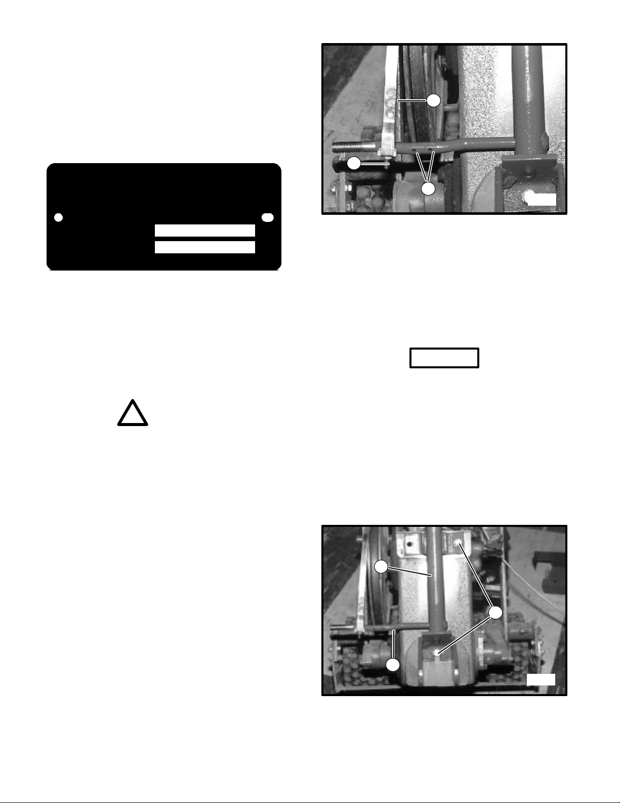
6. Slide adjustment end of brake band over the guard
support rod as shown in Figure 2.
5159
1
2
3
FIGURE 2
1. Brake Band
2. Cotter Pin Holes
3. Adjustment Screw
7. Insert one (1) cotter pin on each side of brake band,
using the two (2) cotter pin holes shown in Figure 2.
BE SURE the heads of the cotter pins are on the
pulley side of the support rod to prevent interference
between cotter pin and belt.
NOTICE
To prevent loss of gear lube from bottom hole in gear
case, tip unit forward until lifting handle on front of
unit is resting on the ground.
8. Remove and retain the upper two (2) screws a
n
d
lockwashers from the rear of the gear case. Loosen
the lower screw far enough to allow the handle bar
to slide behind the screw and washer.
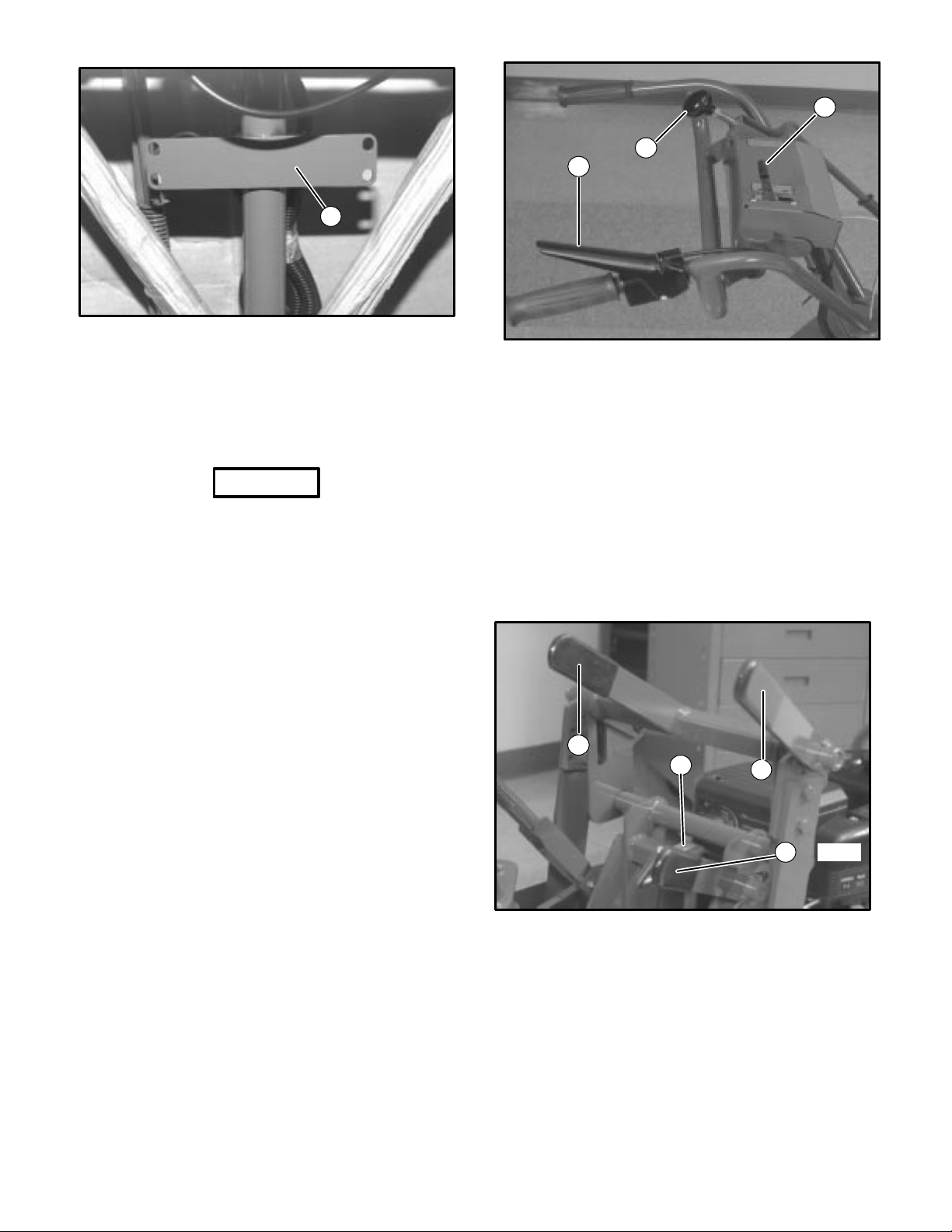
9. Apply Permatex gasket compound or an equivalent to
the three screws (in step 9). Attach handlebar support
to crankcase as shown in Figure 3 and attach the ªLº
bracket shown in Figure 4. BE SURE slotted side of ªLº
bracket is facing toward the large pulley (See Fig. 4).
5159
1
2
3
FIGURE 3
1. Crankcase Screws
2. Handlebar Support
3. Guard Support Rod
5
OPERATION TRAINING VIDEO:
4131316 - JR. Sodcutter Operator Training, English
FIGURE 1
1. Serial Number/Model Number Plate
CGC
COMMERCIAL GROUNDS CARE, INC.
MADE IN U.S.A.
MODEL NUMBER
SERIAL NUMBER
JOHNSON CREEK, WI
1
5386
FIGURE 4
1. “L” Bracket
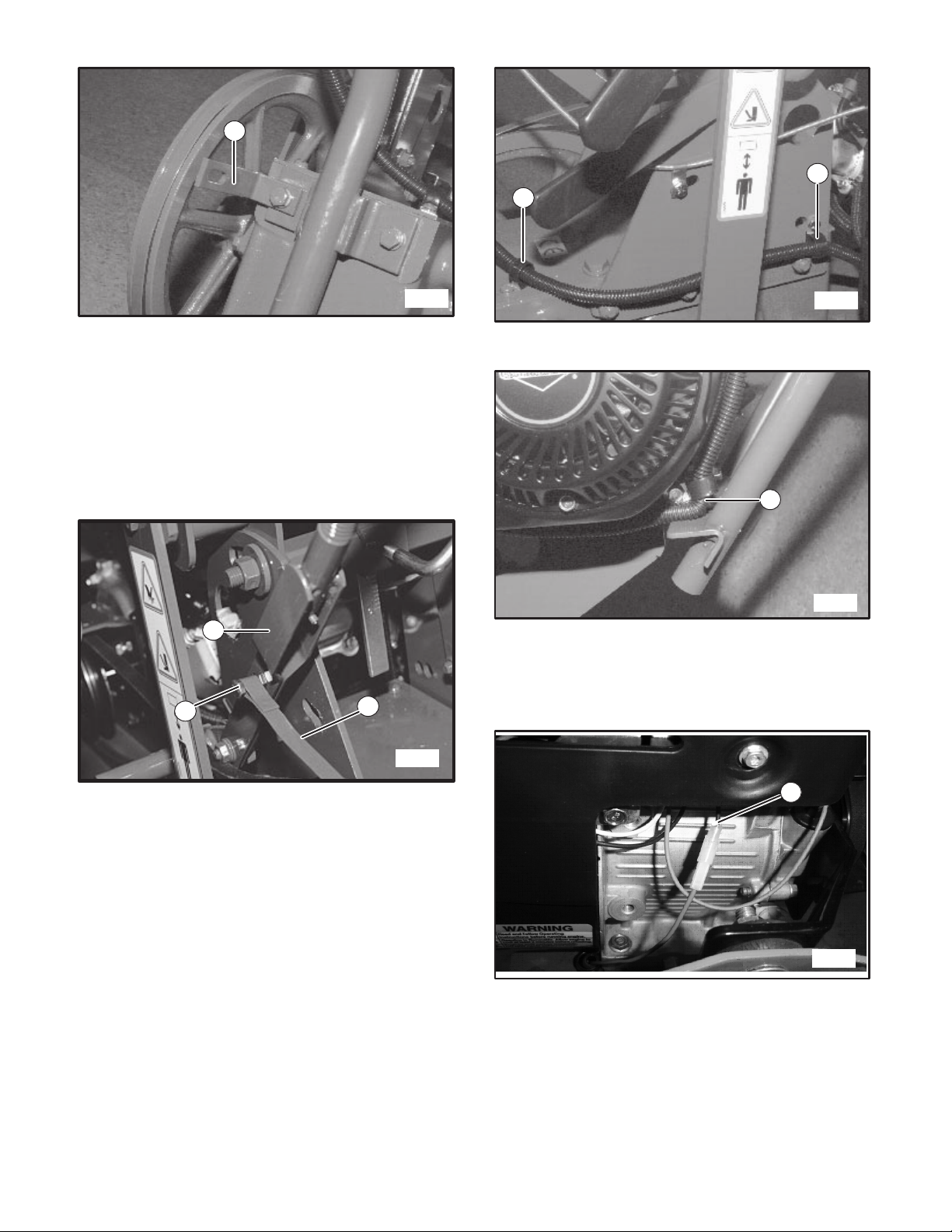
10. Connect clutch control rod to idler pulley assembly.
5169
1
2
3
FIGURE 5
Briggs Engine Shown
1. Brake Band
2. 1/4–20 Screw
3. Clevis
11. Route convoluted tubing from control panel to the
front of the engine and attach at three points shown
in Figures 6 and 7 (for Honda engines route wiring
and cable on the inside of the bracket). Secure hard-
ware.
1
1
5390
FIGURE 6
1. Tubing Clips
1
5391
FIGURE 7
1. Tubing Clip
12. Connect red wire male connector from convoluted
tubing harness to black female connector on front of
engine. See Figure 8 and 9.
1
5392
FIGURE 8
1. Black Female Connector
Briggs Engine Shown
6
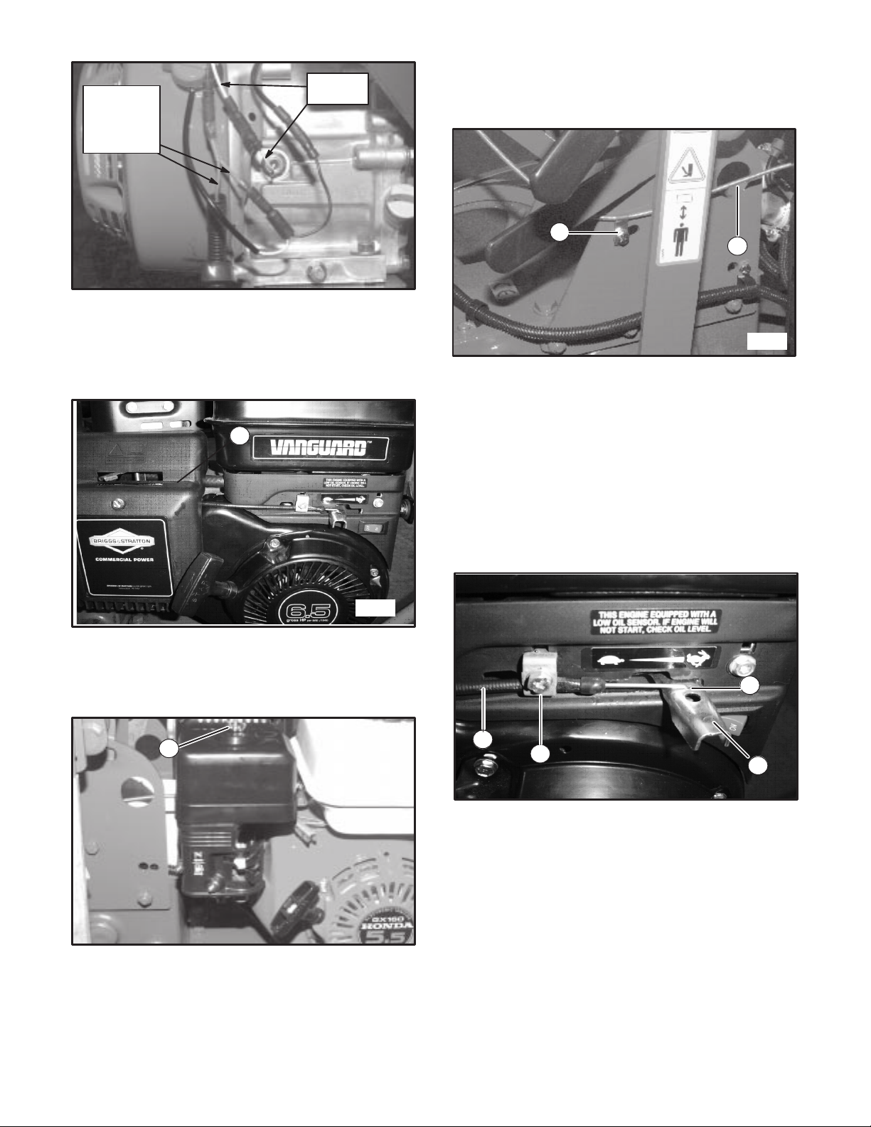
YELLOW
WIRES
RED WIRES
FROM
OPERATOR
PRESENCE
SWITCH
FIGURE 9
Honda Engine Shown
13. Route the throttle cable through the air cleaner
cover as shown. See Figure 10.
1
5393
FIGURE 10
1. Throttle Cover on Briggs Engines
14. For Honda engines loosen and remove wing nut
securing air cleaner cover. Remove cover and ele-
ment to allow access to throttle. See Figure 11.
1
FIGURE 11
1. Wing nut on Honda Engines
15. For Briggs engine route throttle cable to engine and
secure with clamp and hardware as shown in Figure
12 (for Honda engines route cable to the inside of
bracket).
12
5390
FIGURE 12
Briggs Engine Shown
1. Cable Clamp
2. Throttle Cable
34
FIGURE 13
Briggs Engine Shown
1. Z-bend End
2. Engine throttle Lever
3. Throttle Cable
4. Cable Clamp
7
1
2
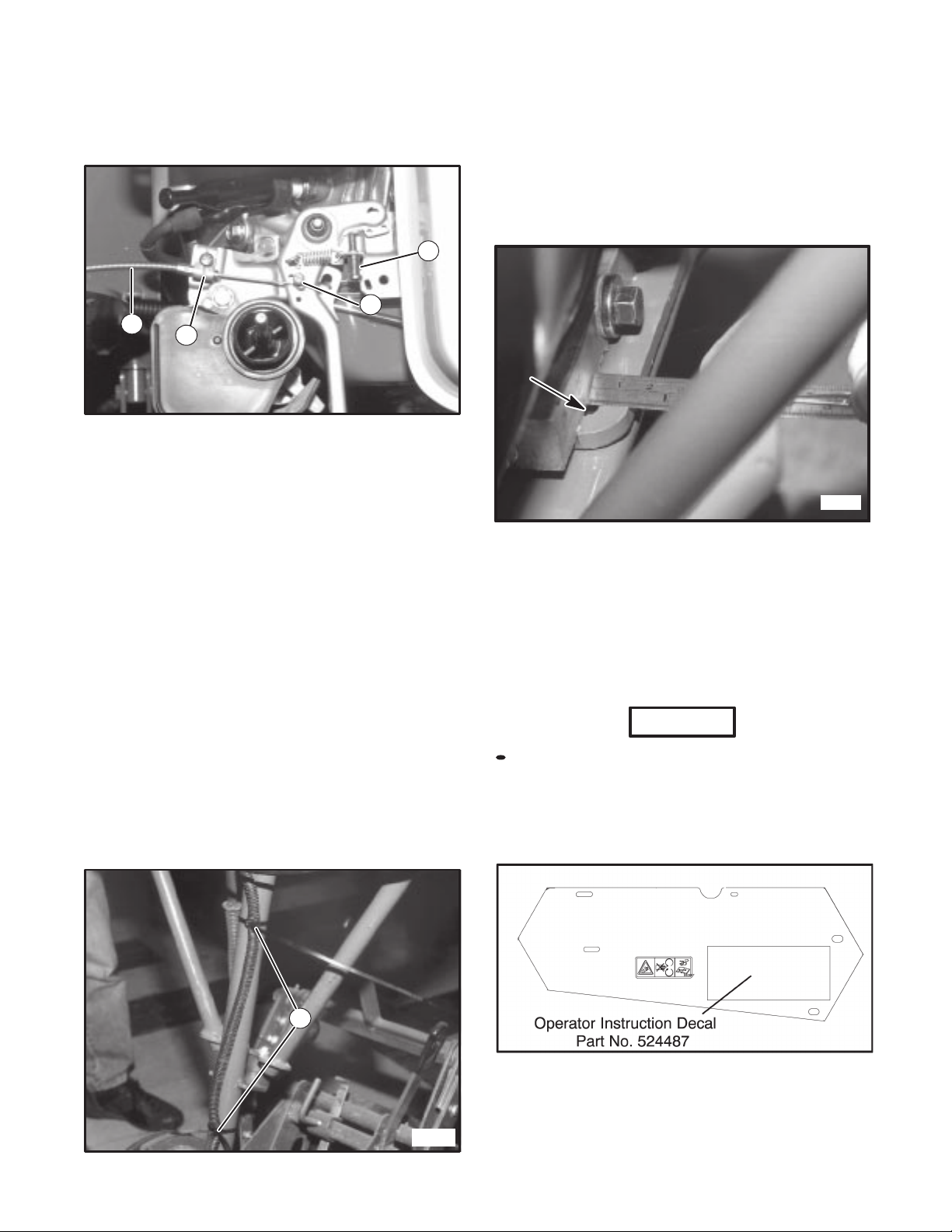
16. For the Briggs engine. Grab the end of the throttle
cable and pull the cable upwards, while turning
the front end down and insert the Z-bend into the
engine throttle lever hole. See Figure 13
NOTE: To make this step easier, the air cleaner
cover can be removed by taking out the
screw.
Move the engine throttle lever full forward. Move the
throttle control lever on the handlebars full forward.
Remove the cable clamp. Position the throttle cable
under the cable clamp screw. Re-install the clamp
screw while pushing the cable body forward. Move
the throttle control back and forth and check for full
high idle. Re-adjust if neccessary. Replace the air
cleaner cover and screw if it was removed.
1
3
2
4
FIGURE 14
Honda Engine Shown
1. Throttle Cable
2. Throttle Bracket
3. Cable Stop
4. Throttle Stop Screw
18. Move throttle control on control panel to low idle
speed
position while inserting cable end through
19. Rotate engine throttle tohigh idle speed position.
Tighten cable screw to secure cable.
DO NOT overtighten cable stop.
20.Pull throttle control on panel back to low idle, then
push back to high dile.
21. If the engine throttle lever is not contacting the end of
the throttle stop screw, the cable stop must be
loosened and the throttle cable wire pulled through the
cable stop further.
22. Reinstall throttle cover. Secure with two original
10mm screws.
23. Use wire ties to secure convoluted tubing to handle-
bar support. See Figure 15.
1
5165
FIGURE 15
1. Wire Ties
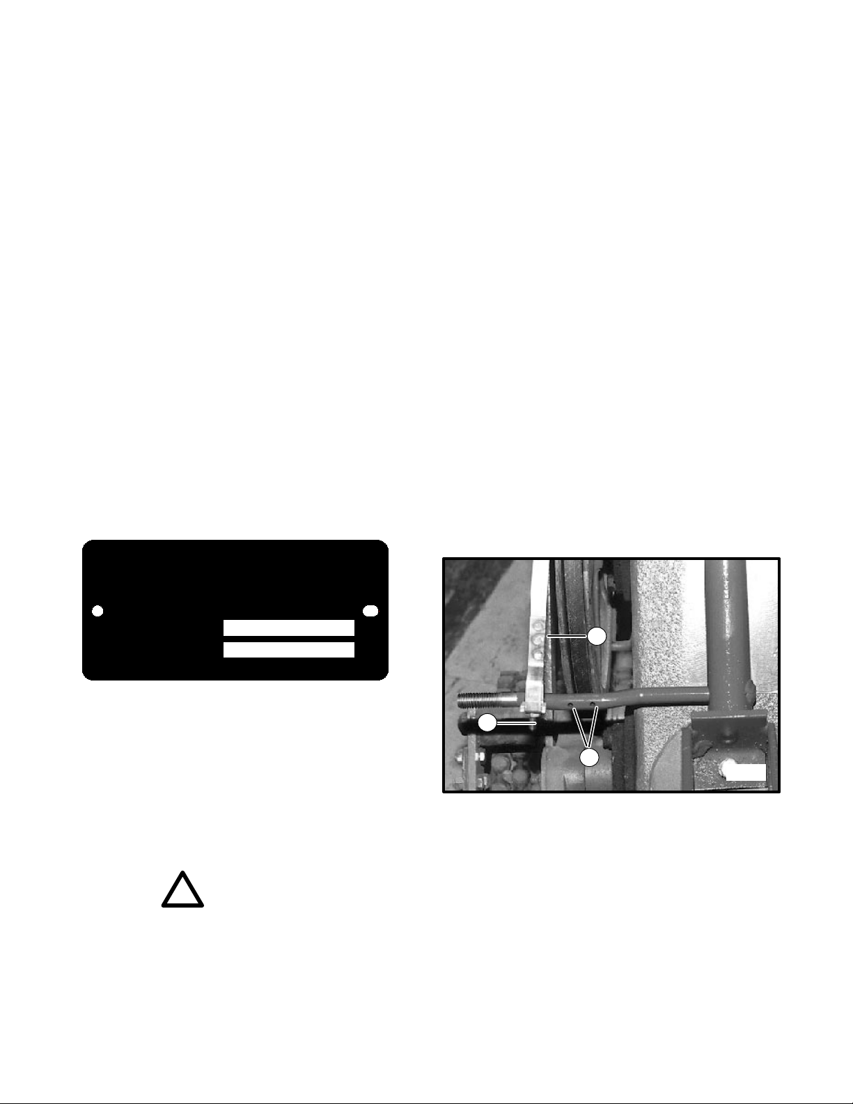
24.Clutch control lever should line up with console corner.
Adjust brake band by turning the adjusting
screw at bottom of brake band with an allen wrench.
Adjustment should be snug enough but not too tight
to cause smoking of the drive belt. Install the locking
nut to hold the brake band adjustment in place.
25. If brake band cannot be adjusted, reposition engine.
Slots on engine plate should be showing 7/32” to
1/4”. See Figure 16.
5175
FIGURE 16
26. Install one (1) 1/2–13 flangelock nut (flange side
towards the outside of the unit) onto the guard sup-
port rod before guard is reinstalled.
27.Reinstall guard onto side of unit using original hard-
ware. Secure “L” bracket to guard using new hard-
ware.
NOTICE
All vehicles operated outside the U.K. in the Euro-
pean community do not apply an operator instruction
decal.
28. In North America and the United Kingdom apply the
operator instruction decal. See following illustration.
29. Insert the two (2) 15 1/2” (394 mm) cable ties through
the holes in the literature mounting plate (See Fig.
17). Secure literature tube using the cable ties.
8
17. For Honda engines route throttle cable through
throttle bracket as shown in Figure 14. The cable end
shoulder should be positioned as shown against the
end of the throttle bracket. Tighten down throttle
bracket making sure not to overtighten.
cable stop.
Move throttle control to high idle speed.
1
FIGURE 17
1. Literature Mounting Plate
30. Attach the cutting blade using six (6) 5/16–24 x 1”
grade 8 screws, lockwashers and nuts. Torque at-
taching hardware to 30 ft.–lbs. (40.7 N⋅m).
NOTICE
Use only the special grade 8 cap screws provided.
Screws below grade 8 will not withstand the recom-
mended torque requirements.
31. Attach throttle control cable to handle using clip
(loose on cable), one (1) #10–24 x 1/2” screw and
lockwasher.
32. Install one (1) 1/2” flangelock nut to the guard sup-
port rod.
CONTROLS
Engine Switch Turn to “ON” position to start
engine. Turn to “OFF” position
to stop engine.
Clutch Control Engages or releases drive belt
Lever and applies brake action to
drive belt when pulled FIRMLY
to rear. See Figure 18, item 1.
Throttle Control Speeds up or slows down
engine. See Figure 18, item 2.
Operator Presence With clutch control engaged,
Control engine will stop if operator
presence lever is not depressed.
See Figure 18, item 3.
4901
FIGURE 18
1. Clutch Control Lever
2. Throttle Control
3. Operator Presence Control
Blade Depth Raises or lowers cutting blade.
Control Lever See Figure 19, item 1.
Blade Angle Adjusts cutting angle of blade.
Locking Lever See Figure 19, item 3.
Blade Depth Locking lever holds blade
Control Locking depth control lever in desired
Lever position. See Figure 19, item 2.
Depth Gauge Allows resetting of blade depth
to the previous cutting height.
1
2
4
4900
3
FIGURE 19
1. Blade Depth Control Lever
2. Blade Depth Control Locking Lever
3. Blade Angle Control Locking Lever
4. Depth Gauge
9
31
2

Blade and wheel Engage and disengage blade
Shifter Handles for cutting and gears for driving
Sodcutter. Refer to Figure 20.
4899
2
1
FIGURE 20
1. Wheel Shifter
2. Blade Shifter
“DISENGAGED” “ENGAGED”
SHIFTER HANDLE
GEAR
CASE GEAR
CASE
SHIFTER
HANDLE
“DISENGAGED” “ENGAGED”
SHIFTER HANDLE
GEAR
CASE GEAR
CASE
FIGURE 21
OPERATION
WARNING
!
To prevent possible bodily injury:
Place all controls in Disengaged position.
524541
DO NOT place hands or feet
under unit at any time.
Hands or feet can be cut or
severed by machinery.
Operator and/or bystanders
should keep a safe distance
from all moving parts of the
Jr. Sodcutter.
DO NOT operate this equipment unless you
have thoroughly read and completely under-
stand the controls and operating sections of
this operators/parts manual.
DO NOT operate sodcutter without all guards in
place. DO NOT make any adjustments or per-
form any maintenance while engine is running.
Never start or run the engine inside where ex-
haust fumes can collect. Carbon monoxide
present in the exhaust is an odorless and deadly
gas. Provide enough fresh air to keep fumes
from getting too strong.
Gasoline is extremely flammable and highly ex-
plosive under certain conditions. ALWAYS stop
engine and DO NOT smoke or allow open flames
or sparks when refueling.
Any warning decal that becomes illegible
should be replaced immediately. When replac-
ing engine, replace sound level warning decal
(Part No. 524538).
If a malfunction should occur, cease operation
immediately. DO NOT operate sodcutter until the
condition has been corrected.
DAILY MAINTENANCE CHECK LIST
*Check engine oil level.
*Check air filter element.
Check engine for loose, broken, or missing
parts.
Check rest of machine for loose, broken, or
missing parts.
*Check fuel level.
*Refer to engine owners manual for oil, fuel,
and maintenance recommendations
10

XX
dB
94
dB
CAUTION
!
To prevent possible hearing loss, hearing
protection should be worn when operating the
Jr. Sodcutter. The preceding decal is used on the
Jr. Sodcutter to remind operators to always wear
adequate hearing protection.
STARTING ENGINE
1. Be sure gas is turned on. Check shut–off valve lo-
cated on the bottom side of the fuel tank.
2. Place all controls in “Disengaged” position.
3. Put throttle lever at half speed.
4. Turn engine switch to “ON” position.
5. Pull recoil starter, and choke as required to start en-
gine. Allow engine to warm up.
MOVING OF UNIT
To move unit without running blade:
Place blade shifter handle in “disengaged” position
(handle will point straight out from unit). Refer to Fig-
ure 21.
Set engine speed at slow speed.
Engage drive shifter handle.
Depress operator presence control.
Engage operator presence control.
Engage clutch control lever.
Adjust throttle to desired walking speed.
To move unit without running engine, put drive shifter
handle and clutch control lever in “Disengaged” position.
ADJUSTING OPERATOR
PRESENCE CONTROL
1. To adjust operator presence cable, pull clutch control
handle rearward as far as possible.
2. Press operator presence handle (right handlebar)
down as far as possible.
3. Adjust cable until the pivot arm contacts the arm
extending from the operator presence switch (see
Figure 22).
4. Tighten cable clamp to secure cable. Check for
proper operation.
1
2
3
5388
FIGURE 22
1. Clutch Control Handle
2. Operator Presence Switch Arm
3. Pivot Arm
ADJUSTING BLADE ANGLE
Loosen blade angle control locking lever and move H–
frame forward or backward until blade is at desired angle
of pitch. Tighten blade angle control locking lever. See
Figure 19.
ADJUSTING DEPTH OF CUT
1. Make a trial run in turf. Set depth to cut approxi-
mately 3/4” of soil.
2. Loosen depth gauge handle (see Figure 19). Adjust
depth gauge to contact bottom on depth control
lever.
3. Loosen depth control locking lever and lower depth
control until it rests on depth gauge.
4. Tighten depth control locking lever.
NOTICE
Numbers on depth gauge do not necessarily rep-
resent thickness of sod being cut.
BLADE ANGLE (PITCH)
Under normal operating conditions, blade angle (Figure 23)
is minimal (blade bottom is flat). In extremely hard soil or
when cutting with a dull blade, the blade may want to ride
out of the ground. It may then help to adjust blade angle
downward (see Adjusting Blade Angle above). A short
trial run will indicate which is the best blade angle.
SIDE ARM
DRIVE
WHEEL BLADE
BOTTOM
BLADE
ANGLE
(Pitch)
FIGURE 23
11

CUTTING SOD
1. Engage drive wheel shifter handle.
2. Engage blade shifter handle.
3. Standing on the right side of unit, lift handle with left
hand, and lower blade to preset depth with right
hand.
4. Adjust throttle to full speed.
5. Push clutch lever forward and lower handle.
6. After cutting a short distance, stop unit and check
thickness of sod. Adjust if necessary.
7. At end of each cutting pass, lift up on handle to clear
cutting blade from sod, retard throttle and turn Jr.
Sodcutter around for return pass.
STORAGE INSTRUCTIONS
WARNING
!
To prevent possible explosion or ignition of va-
porized fuel, DO NOT store equipment with fuel
in tank or carburetor in enclosure with open
flame (Example: Furnace or water heater pilot
light).
Daily Storage
Check engine oil level and air filter element daily.
Check oil level in gear case.
Close fuel valve at bottom of fuel tank.
Clean cutting blade (grass, dirt, etc.).
NOTICE
For extended storage, refer to the service and
parts manual
Transporting Unit
When transporting unit on trailer or truck, shut fuel valve
“OFF” beneath fuel tank.
DATE NOTES
12

INFORMACION GENERAL
¡IMPORTANTE!
ESTE MANUAL LE AYUDARA EN LA OPERACION
SEGURA Y MANTENIMIENTO APROPIADO DE SU
EQUIPO. LEA EL MANUAL MINUCIOSAMENTE
ANTES DE INTENTAR CUALQUIER CLASE DE
OPERACION. PONGASE EN CONTACTO CON EL
DISTRIBUIDOR AUTORIZADO SI CUALQUIER PARTE
NO ES ENTENDIDA COMPLETAMENTE.
Los siguientes dos simbolos son utilizados a lo largo de
este manual para asegurarnos que usted esta
completamente enterado de la informaci n de seguridad
y servicio.
!Este simbolo es utilizado a lo largo del manual
para alertarlo con informacion acerca de acciones o
situaciones inseguras y sera seguido por la palabra
PELIGRO, ADVERTENCIA o PRECAUCION. PELIGRO
indica riesgos inmediatos los cuales podrian ocasionar
lesion severa o muerte. ADVERTENCIA indica acciones
o situaciones inseguras que pudiesen causar lesion
~severa, muerte y/o dano mayor del equipo o de la
propiedad. PRECAUCION indica acciones o situaciones
inseguras que pudiesen causar lesi n y/o dano menor
del equipo o la propiedad.
AVISO Este simbolo aparece cerca de informacion
o de instrucciones las cuales le ayudaran a operar y a
mantener su equipo en la forma correcta.
!ADVERTENCIA
La informacion y las instrucciones incluidas en
este manual lo alertan de ciertas cosas que debe
de hacer muy cuidadosamente. Si no lo hace
usted podria:
herirse a si mismo o herir a otros
herir a la persona a su lado la cual opera el
equipo
danar el equipo.
Este manual contiene informacion esencial
acerca de la operacio n y principios de
seguridad, y debe permanecer en la unidad a
toda hora al alcance de cualquier operador.
Existen manuales adicionales disponibles con su
distribuidor.
¡IMPORTANTE!
ESTE EQUIPO NO DEBE SER MODIFICADO O NO SE
LE DEBEN AADIR P ARTES SIN LA AUTORIZACION
DEL FABRICANTE.
!ADVERTENCIA
El alterar este equipo en cualquier forma podria
afectar adversamente la operacion, desempeno,
dourabilidad o el uso del equipo y puede crear
situaciones de riesgo.
Dirija sus preguntas a:
Commercial Grounds Care, Inc.
One Bob-Cat Lane
P.O. Box 469
JohnsonCreek, WI 53038-0469 USA
INFORMACION ESPECIFICA
Toda la informacion contenida en este manual fue la
informacion disponible mas actualizada en el momento
de imprimir este manual. Commercial Grounds Care, Inc.
se reserva el derecho de hacer cambios en
cualquier momento sin aviso.
Siempre que sea especificado un producto de marca
puede ser utilizado un producto equivalente a menos
que sea descrito de otra forma.
CAMBIO DE PROPIEDAD
O DIRECCION
Commercial Grounds Care, Inc. hace todos los
esfuerzos necesarios para mantener a los propietarios
actualizados con toda la informaci n de seguridad
relacionada. Por tanto, los cambios en la propiedad y/o
la direcci n deben ser reportados al fabricante.
Su distribuidor tiene FORMULARIOS DE CAMBIO DE
REGISTRO los cuales ser n llenados y archivados por
el distribuidor para que hagan parte de sus archivos, y
ser enviada una copia al fabricante.
SPANISH 13

CALCOMANIAS ILUSTRADAS
94
dB
94
dB
524541
Esta calcomanía instruye al operador para que lea y
entienda el manual del operador. Para evitar lesiones el
operador tiene que estar familiarizado con la operación
de este producto y estar completamente enterado de
los procedimientos de operación segura.
Esta calcomanía le informa al operador que
debe ser utilizada protección para el sentido
del oído si opera el Cortacésped Jr. por
períodos de tiempo prolongados (por más de
cuatro horas).
Este símbolo de la parte superior muestra
dedos o manos que están siendo cortadas o
seccionadas. NO coloque las manos o los
dedos por debajo del Cortacésped Jr. mientras
opere la unidad.
Este símbolo de la mitad muestra los dedos de
los pies y los pies siendo cortados o
seccionados. NO coloque los pies o los dedos
de los pies por debajo del Cortacésped Jr.
mientras opera la unidad.
Los símbolos utilizados en la parte inferior de
la calcomanía son usados para informar al
operador y/o las personas alrededor, que se
mantengan a una distancia segura y alejados
de la maquinaria. Puede ocurrir lesión
personal si no mantiene las manos y pies
alejados de la maquinaria a una distancia
segura.
La calcomanía de control del regulador utiliza
la tortuga para representar velocidades lentas
del motor, la liebre representa velocidades
rápidas del motor.
009034910
SPANISH 14

CALCOMANIAS ILUSTRADAS
Esta calcomanía indica que la unidad está
certificada para uso en la comunidad Europea.
524485
524486
840697
El símbolo de la izquierda es
usado para mostrar el posible
resultado de trabajar en la
maquinaria sin las
protecciones de seguridad.
Las manos y los dedos
pueden quedar enredados en
las correas. NO opere la
unidad sin las protecciones
de seguridad en su lugar. Los símbolos del centro le
informan al operador y/o a las
personas alrededor el mantener
las manos alejadas de los
componentes en movimiento.
Los símbolos de la derecha
instruyen al operador para que
lea la sección de servicio del
manual del operador. Desactive el
motor (desconecte el cable de la
bujía) antes de realizar cualquier
servicio o mantenimiento de la
unidad.
Dirección del enganche de la manija.
Esta calcomanía muestra la dirección del
movimiento de la palanca utilizada para
enganchar las ruedas motrices del
Cortacésped Jr. El movimiento en la dirección
opuesta detendrá las ruedas motrices.
Dirección del enganche de la manija.
Esta calcomanía muestra la dirección del
movimiento de la palanca utilizada para
enganchar la cuchilla cortadora. El
movimiento en la dirección opuesta detendrá
la cuchilla.
Empuje la palanca hacia adelante para
enganchar la correa de la transmisión.
Tire de la palanca hacia atrás para
desenganchar la correa de la transmisión.
SPANISH 15

IDENTIFICACION DEL EQUIPO
544844 Cortacésped Jr. – 12 pulgadas (305 mm). . .
544845E Cortacésped Jr. – 18 pulgadas (457 mm). . .
544944A Cortacésped Jr. – 12 pulgadas (305 mm). . . .
544945A Cortacésped Jr. – 18 pulgadas (457 mm). . . .
INDICE
NUMEROS DE IDENTIFICACION DEL EQUIPO
Número de Serie y placa del Número
del Modelo 17. . . . . . . . . . . . . . . . . . . . . . . . . . . . . . . .
INFORMACION GENERAL 13. . . . . . . . . . . . . . . . . . . .
OPERACION
Almacenamiento 25. . . . . . . . . . . . . . . . . . . . . . . . . .
Cambio de propiedad 13. . . . . . . . . . . . . . . . . . . . . .
Controle 22-23. . . . . . . . . . . . . . . . . . . . . . . . . . . . . . . . .
EncendidodelMotor..........................24
MoviendolaUnidad.........................24
Cortando el Césped.........................25
Lista de revisión para mantenimiento diario . . . . 23
Transporte de la Unidad .....................25
PREPARACIÓN 17-21. . . . . . . . . . . . . . . . . . . . . . . . . . .
AJUSTES:
Ajuste de Profundidad de la Cuchilla 24-25. . . . . .
Angulo de la Cuchilla 24. . . . . . . . . . . . . . . . . . . . . .
Interruptor de presencia del operador 24. . . . . . . .
ESPECIFICACIONES
Calcomanías ilustradas 14-15. . . . . . . . . . . . . . . . .
Cortacésped 16-17. . . . . . . . . . . . . . . . . . . . . . . . . .
Pintura para retoques 17. . . . . . . . . . . . . . . . . . . . . .
ESPECIFICACIONES
MODELOS: 544844E, 544845E
Motor B&S Vanguard de 4 ciclos – 6.5 H.P.,.. . . . . .
Modelo 12H332, Tipo 0115, Trim B8, 12.5 pul. cúbicas
(205 cc)con arranque de retroceso. Regulador colocado
a 3600 +/– 100 rpm, sin carga.
Nivel de Ruido .. . . . . . . . . . . . . . . . . . . . . . . . . . . . . . . . .
Nivel de sonido –88 dB(A) (basado en presión)
Nivel de sonido – 99 dB(A) (basado en poder)
Vibración Nivel de vibración del manubrio en el eje. . . .
z – 29.4 metros por segundo al cuadrado
Embrague .. . . . . . . . . . . . . . . . . . . . . . . . . . . . . . . . . . . . .
Tipo apretador de correa activado por resorte.
Reducción Motor a cuchilla 2.94:1. . . . . . . . . . . . . . . . .
Motor a ruedas motrices 55.8:1
Ruedas Transmisión: diá. 8” (203 mm) con. . . . . .
rodadura dentada vulcanizada al cubo.
Posterior: 8 x 1.75 semi neumática con chumaceras de
bolas pre–empacadas.
Transmisión Correa de la sección ”A” del motor a la.
caja de engranajes, cadena de rodillo en la caja de
engranajes al eje de la transmisión y la transmisión de la
cuchilla.
Caja de Engranajes Lubricación: EP140 Gear Lube. .
Capacidad: 3 1/2 Pintas (1.7L)
Ancho del corte 11 3/4” (298 mm). . . . . . . . . . . . . . . . .
18” (457 mm)
Velocidad de la cuchilla .. . . . . . . . . . . . . . . . . . . . . . . .
1225 oscilaciones/min. a 3600 rpm
Distanciamiento de la cuchilla .. . . . . . . . . . . . . . . . . .
Ajuste con palanca de mano, variable de 0 a 9 grados
Peso122.1 kg (269 lb.). . . . . . . . . . . . . . . . . . . . . . . . . . .
148.5 kg (327 lb.)
Dimensiones Ancho: 24” (600 mm). . . . . . . . . . . . . . . .
Alto: 33” (838 mm)
Largo: 49” (1,244 mm)
Base de las ruedas: 19” (483 mm)
Estándares Conforme al estándar de la Comunidad. .
Europea 89/392 y enmiendas 91/368 y 93/44. CARB,
EPA.
MODELOS: 544944A, 544944A
Motor Honda GX160 OHV 4 ciclos – 6.0 H.P.,. . . . . . .
Modelo GX160–K1QX2, 9.9 pul. cúbicas (163 cc) con
arranque de retroceso. Regulador colocado a 3600 +/–
100 rpm, sin carga.
Nivel de Ruido .. . . . . . . . . . . . . . . . . . . . . . . . . . . . . . . . .
Nivel de sonido –92 dB(A) (basado en presión)
Nivel de sonido – 105 dB(A) (basado en poder)
Vibración Nivel de vibración del manubrio en el eje. . . .
z – 32.4 metros por segundo al cuadrado
Embrague .. . . . . . . . . . . . . . . . . . . . . . . . . . . . . . . . . . . . .
Tipo apretador de correa activado por resorte.
Reducción Motor a cuchilla 2.94:1. . . . . . . . . . . . . . . . .
Motor a ruedas motrices 55.8:1
Ruedas Transmisión: diá. 8” (203 mm) con. . . . . .
rodadura dentada vulcanizada al cubo.
Posterior: 8 x 1.75 semi neumática con chumaceras de
bolas pre–empacadas.
Transmisión Correa de la sección ”A” del motor a la.
caja de engranajes, cadena de rodillo en la caja de
engranajes al eje de la transmisión y la transmisión de la
cuchilla.
Caja de Engranajes Lubricación: EP140 Gear Lube. .
Capacidad: 3 1/2 Pintas (1.7L)
Ancho del corte 11 3/4” (298 mm). . . . . . . . . . . . . . . . .
18” (457 mm)
Velocidad de la cuchilla .. . . . . . . . . . . . . . . . . . . . . . . .
1225 oscilaciones/min. a 3600 rpm
Distanciamiento de la cuchilla .. . . . . . . . . . . . . . . . . .
Ajuste con palanca de mano, variable de 0 a 9 grados
SPANISH 16
E
Peso 122.1 kg (269 lb.). . . . . . . . . . . . . . . . . . . . . . . . . . .
148.5 kg (327 lb.)
Dimensiones Ancho: 24" (600 mm). . . . . . . . . . . . . . . .
Alto: 33" (838 mm)
Largo: 49" (1,244 mm)
Base de las ruedas: 19" (483 mm)
Est€ndares Conforme al est€ndar d e la Comunidad. .
Europea 89/392 y enmiendas 91/368 y 93/44. CARB,
EPA.
PINTURA PARA RETOQUES
Verde Ransomes
Caneca atomizadora de 16 oz. (0.5l), ordene el No. de
Parte 838140
Caneca de 1 qt. (0.95L), ordene el No. de Parte 838141
NUMERO DE SERIE Y PLACA DEL
NUMERO DEL MODELO
El numero de serie y la placa del numero del modelo del
Cortacesped Jr. son mostrados m€s adelante. La placa
est€ localizada en la parte superior de la caja de
engranajes en la parte posterior de la unidad, justo en
frente de la ubicaci•n del montaje del manubrio.
FIGURA 1
1. Numero de Serie/Placa del Numero del Modelo
INSTALACION
!ADVERTENCIA
Para evitar lesiones serias, SIEMPRE use el
proteccion ocular y permanezca a una
distancia prudente cuando este cortando el
material de embandado. El material de
embandado esta bajo tension y puede rebotar
bruscamente cuando lo corte.
NUNCA desactive el control de presencia del
operador; no lo altere o modifique de ninguna
manera.
El Sodcutter (Cortadora de Cesped) es
bastante pesado. Para evitar lesiones utilice un
dispositivo elevador adecuado (por ejemplo
una grua, montacargas, etc.) para retirarlo de
la tarima de envio.
1. Quite y descarte el material de embandado que esta€
asegurando el Jr. Sodcutter a la tarima.
2. Quite y descarte la cinta reforzada que est€
asegurando el manubrio y el conjunto de control del
embrague a la tarima.
3. Retire el Jr. Sodcutter de la tarima de env‹o
utilizando un dispositivo elevador adecuado.
4. Retire la bolsa de herrajes y vacie su contenido
sobre una superficie donde los herrajes no vayan a
refundirse o perderse.
5. Afloje, quite y conserve los herrajes que aseguran el
protector a la parte lateral de la unidad. Quite el
protector para permitir acceso al conjunto de la
polea intermedia y a los componentes de la banda
del freno.
6. Mueva el extremo de ajuste de la banda del freno
sobre la varilla de soporte del protector como se
muestra en la Figura 2.
5159
1
2
3
FIGURA 2
1. Banda del Freno
2. Orificios del Pasador de Chaveta
3. Tornillo de Ajuste
7. Coloque un (1) pasador de chaveta en cada lado de
la banda del freno utilizando los dos (2) orificios para
pasador de chaveta mostrados en la Figura 2.
ASEGURESE que las cabezas de los pasadores de
chaveta esten en el lado de la polea de la varilla de
soporte para evitar la interferencia entre el pasador
de chaveta y la correa.
SPANISH 17
OPERATION TRAINING VIDEO:
4131317 - JR. Sodcutter Operator Training, Spanish
CGC
CGC
COMMERCIAL GROUNDS CARE, INC.
COMMERCIAL GROUNDS CARE, INC.
MADE IN U.S.A.
MADE IN U.S.A.
MODEL NUMBER
MODEL NUMBER
SERIAL NUMBER
SERIAL NUMBER
JOHNSON CREEK, WI
JOHNSON CREEK, WI

AVISO
Para evitar la pérdida de lubricante para
engranajes por el orificio del fondo de la caja de
engranajes, incline la unidad hacia adelante hasta
que la manija de elevación de la parte delantera
de la unidad descanse sobre el piso.
8. Quite y conserve los dos (2) tornillos y arandelas de
seguridad de la parte trasera de la caja de
engranajes. Afloje el tornillo inferior lo suficiente
para permitir que el manubrio se deslice por detrás
del tornillo y la arandela.
9. Aplique compuesto para empaquetaduras
Permatex, o un equivalente, a los tres tornillos (en el
paso 9). Una el soporte del manubrio al cárter, como
es mostrado en la Figura 3, y conecte la ménsula en
“L” mostrada en la Figura 4. ASEGURESE que el
lado con ranuras de la ménsula en “L” esté colocada
de frente a la polea grande. Refiérase a la Figura 4.
5159
1
2
3
FIGURA 3
1. Tornillos del Cárter
2. Soporte del Manubrio
3. Varilla de Soporte del Protector
1
5386
FIGURA 4
1. Ménsula en “L”
10. Conecte la varilla de control del embrague al
conjunto de la polea intermedia.
5169
1
2
3
FIGURA 5
1. Banda del Freno
2. Tornillo de 1/4–20
3. Horquilla
11. Pase la tubería enroscada del panel de control hacia
la parte delantera del motor y conéctela en los tres
puntos mostrados en las Figuras 6 y 7. (En los
motores Honda, pase el alambrado y el cable por la
parte interior de la ménsula). Asegure los herrajes.
11
5390
FIGURA 6
1. Sujetadores de la Tubería
1
5391
FIGURA 7
1. Sujetador de la Tubería
12. Instale el conector macho del alambre rojo del
colector de cables de la tubería enroscada al
SPANISH 18
This manual suits for next models
3
Table of contents
Languages:
Popular Cutter manuals by other brands

Mejix
Mejix CCE 200 Original manual translation

Maruyama
Maruyama M27QC Owner's/operator's manual

Chicago Pneumatic
Chicago Pneumatic CP861 instruction manual

KEENCUT
KEENCUT Evolution E2 User instructions

Logan Graphic Products
Logan Graphic Products 650-1 instruction manual

Scheppach
Scheppach HSC130 Translation of original instruction manual


