CGC Ryan 544946A Programming manual

OPERATOR / PARTS MANUAL
MAN 4163416
Rev. A 6-2008
MODELS:
544946A
JR. SODCUTTER, HONDA 18”

CALIFORNIA
Proposition 65 Warning
Diesel engine exhaust and some
of its constituents are known to the
State of California to cause cancer,
birth defects and other reproductive
harm.
Californie Proposition 65 Avertissement
Leséchappementsdesmoteursdieseletcertains
de leurs composés sont reconnus par l’Etat de
Californie pour être cancérigènes, provoquer
des défauts congénitaux et d’autres dangers en
matière de reproduction.
ADVERTENCIA
AVERTISSEMENT
WARNING
The engine exhaust from this product
contains chemicals known to the State
of California to cause cancer, birth
defects or other reproductive harm.
California Advertencia
de la Proposicion 65
El estado de California hace saber que
los gases de escape de los motores diesel
y algunos de sus componentes producen
cáncer, defectos de nacimiento y otros
daños en el proceso de reproducción
humana.
L’
é
mission du moteur de ce mat
é
riel con-
tient des produits chimiques que l’Etat de
Californie consid
è
re
ê
tre canc
é
rig
è
nes,
provoquer des d
é
fauts cong
é
nitaux et
d’autres dangers en mati
è
re de reproduc-
tion.
El estado de California hace saber que los
gasesdeescapedeesteproductocontienen
productosquÍmicosqueproducencáncer,
defectos de nacimiento y otros daños en
el proceso de reproducción humana.
CALIFORNIA
Proposition 65 Warning
Battery posts, terminals, wiring
insulation, and related accessories
contain lead and lead compounds,
chemicals known to the State of
California to cause cancer and birth
defects or other reproductive harm.
WASH HANDS AFTER HANDLING.

1
Jr.
Sodcutter
06-2008
IMPORTANT MESSAGE
Thank you for purchasing this CGC, Inc. product. You have purchased a world class product, one of the best
designed and built anywhere.
This machine comes with an Operation and Safety Manual and a separate Parts and Maintenance Manual. The
useful life and good service you receive from this machine depends to a large extent on how well you read and
understand these manuals. Treat your machine properly, lubricate and adjust it as instructed, and it will give
you many years of reliable service.
Your safe use of this CGC, Inc. product is one of our prime design objectives. Many safety features are built in,
but we also rely on your good sense and care to achieve accident-free operation. For best protection, study the
manual thoroughly. Learn the proper operation of all controls. Observe all safety precautions. Follow all instruc-
tions and warnings completely. Do not remove or defeat any safety features. Make sure those who operate
this machine are as well informed and careful in its use as you are.
See a CGC, Inc. dealer for any service or parts needed. CGC, Inc. service ensures that you continue to receive
the best results possible from CGC, Inc. products. You can trust CGC, Inc. replacement parts because they are
manufactured with the same high precision and quality as the original parts.
CGC, Inc. designs and builds its equipment to serve many years in a safe and productive manner. For longest
life, use this machine only as directed in the manual, keep it in good repair and follow safety warnings and in-
structions. You'll always be glad you did.
Commercial Grounds Care, Inc.
One Bob Cat Lane
Johnson Creek, WI 53038-0469
TABLE OF CONTENTS........................................ FIGURES ................................................................... PAGE
SAFETY............................................................................................................................................................2
LABELS........................................................................................................................................................3, 4
SET-UP..........................................................................................................................................................5-8
CONTROLS................................................................................................................................................9, 10
OPERATION................................................................................................................................................... 11
SERVICE...................................................................................................................................................12-21
STORAGE ......................................................................................................................................................22
TROUBLE SHOOTING ..................................................................................................................................23
SPECIFICATIONS.......................................................................................................................................... 24
PARTS SECTION........................................................................................................................................... 25
DRIVE ASSEMBLY AND SIDE COVER .............. FIGURE 1 ................................................................... 26, 27
GEAR CASE........................................................ FIGURE 2 ................................................................... 28, 29
SIDE ARMS, PITMAN ARMS AND HANDLES.... FIGURE 3 ................................................................... 30, 31
HANDLEBAR ASSEMBLY................................... FIGURE 4 ...................................................................32, 33
2
Jr.
Sodcutter
MODEL NUMBER: This number appears on
sales literature, technical manuals and price lists.
SERIAL NUMBER: This number appears only
on your mower. It contains the model number
followed consecutively by the serial number.
Use this number when ordering parts or seeking
warranty information.
SAFETY
NOTICE !!!
Unauthorized modications may present extreme
safety hazards to operators and bystanders and
could also result in product damage.
Commercial Grounds Care, Inc. strongly warns
against, rejects and disclaims any modications,
add-on accessories or product alterations that are
not designed, developed, tested and approved by
CGC, Inc.'s Engineering Department. Any CGC,
Inc. product that is altered, modied or changed in
any manner not specically authorized after original
manufacture–including the addition of “after-market”
accessories or component parts not specically
approved by CGC, Inc.–will result in the CGC, Inc.
Warranty being voided.
Any and all liability for personal injury and/or property
damage caused by any unauthorized modications,
add-on accessories or products not approved by
CGC, Inc. will be considered the responsibility
of the individual(s) or company designing and/or
making such changes. CGC, Inc. will vigorously
pursue full indemnication and costs from any party
responsible for such unauthorized post-manufacture
modications and/or accessories should personal
injury and/or property damage result.
This symbol means:
ATTENTION!
BECOME ALERT!
Your safety and the safety of others is involved.
Signal word denitions:
The signal words below are used to identify levels
of hazard seriousness. These words appear in
this manual and on the safety labels attached
to CGC, Inc. machines. For your safety and the
safety of others, read and follow the information
given with these signal words and/or the symbol
shown above.
DANGER indicates an imminently hazardous
situation which, if not avoided, WILL result in death
or serious injury.
WARNING indicates a potentially hazardous
situation which, if not avoided, COULD result in
death or serious injury.
CAUTION indicatesa potentiallyhazardoussituation
which, if not avoided, MAY resultinminor or moderate
injury. It may also be used to alert against unsafe
practices or property damage.
CAUTION used without the safety alert symbol
indicates a potentially hazardous situation which, if
not avoided, MAY result in property damage.

3
Jr.
Sodcutter
LABELS
524538
This decal informs the operator that hearing
protection should be worn if operating the
Jr. Sodcutter for extended periods of time (longer
than four hours).
dB
94
840697
009034910
This decal instructs the operator to read and
understand the Operation & Safety manual. To
prevent injury, they must be familiar with the
operation of this product and be fully aware of safe
operating procedures.
524541
The top symbol shows ngers or hands being cut or
severed. DO NOT place hands or ngers under Jr.
Sodcutter while operating the unit.
The middle symbol shows toes or feet being cut
or severed. DO NOT place feet or toes under Jr.
Sodcutter while operating the unit.
The lower symbol informs the operator and/or
bystanders to keep a safe distance away from
machinery. If you do not keep hands and feet a safe
distance from the machinery, personal injury could
occur.
524481
The throttle control decal uses the turtle to represent
slower engine speeds, the rabbit represents faster
engine speeds.
840697
The left symbol shows the possible result of working
on the machinery with safety shields removed.
Hands and ngers may become entangled in belts.
DO NOT operate the unit without safety shields in
place.
The middle symbol warns the operator and/or
bystanders to keep hands out of moving components.
The right symbol instructs the operator to read the
service section of the operators manual. Disable
the engine (disconnect spark plug wire) before
performing any service or maintenance on the unit.
4
Jr.
Sodcutter
LABELS
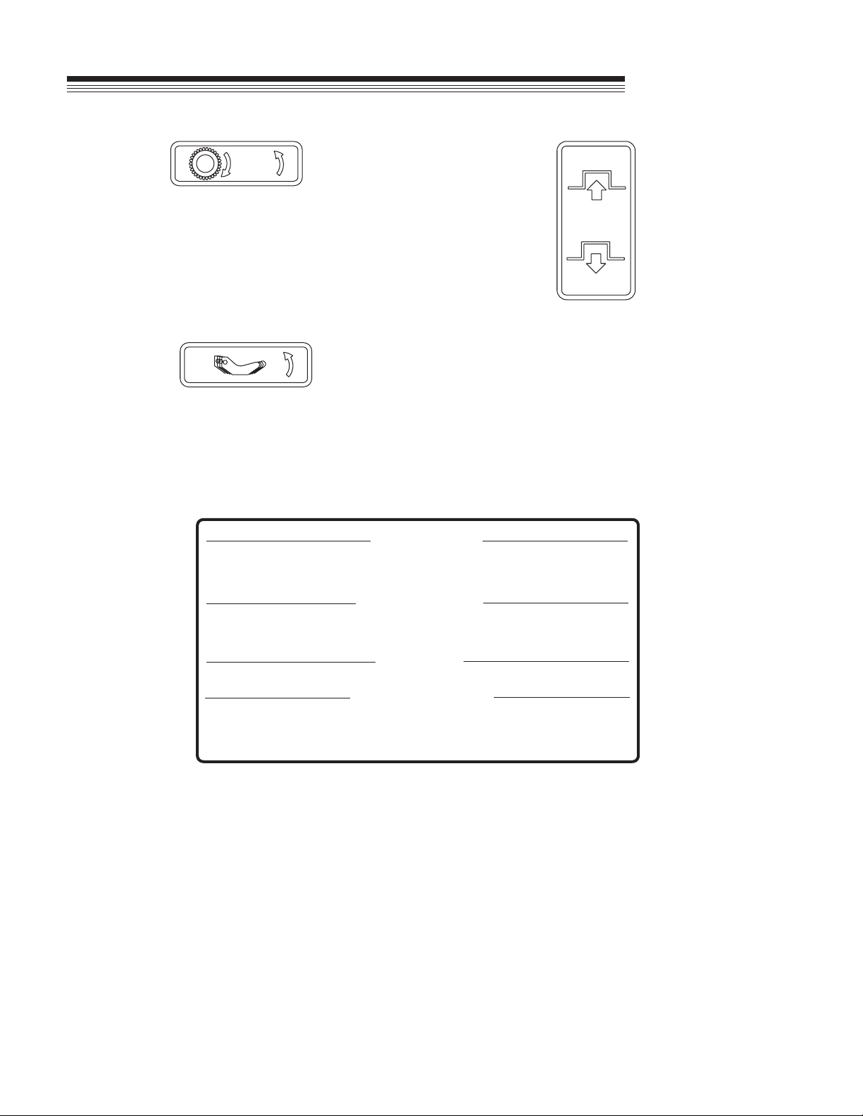
524485
This decal shows the direction of lever movement
used to engage the cutter blade of the Jr. Sodcutter.
Movement in the opposite direction will stop the
cutter blade.
4124337
This decal shows the operating instructions for the Jr.
Sodcutter.
524480
This decal shows the direction of lever movement
used to engage the drive belt of the Jr. Sodcutter.
Push the lever forward to engage the drive belt.
Pull the lever rearward to disengage the drive belt.
3. ADJUST BLADE TO CUT SOD 3/4 TO 1 INCH THICK.
HARD SOIL OPERATION:
1. TIP BLADE FORWARD BY LOOSENING LOCKING LEVER (BLACK HANDLE RIGHT SIDE "H" FRAME). PUSH "H" FRAME FORWARD AS REQUIRED AND
LOCK LEVER.
DEPTH OF CUT:
1. LOOSEN UPPER RIGHT HAND LOCKING LEVER. TIP MACHINE FORWARD AND MOVE CENTER DEPTH CONTROL LEVER TO DESIRED DEPTH. LOCK IN
POSITION BY ROTATING LOCKING LEVER CLOCKWISE.
2. LOOSEN DEPTH STOP LOCKING LEVER AT CENTER OF "H" FRAME. RAISE DEPTH STOP UNTIL IT CONTACTS DEPTH CONTROL LEVER AND LOCK
IN PLACE.
TO MOVE WITHOUT POWER:
DISENGAGE DRIVE WHEEL SHIFTER LEVER (ON FRONT-RIGHT SIDE OF MACHINE) BY ROTATING DOWNWARD.
TO MOVE MACHINE UNDER POWER:
1. DISENGAGE CUTTING BLADE SHIFTER LEVER (ON FRONT-RIGHT SIDE OF MACHINE) BY ROTATING DOWNWARD.
2. ENGAGE DRIVE WHEEL SHIFTER LEVER (ON FRONT-RIGHT SIDE OF MACHINE) BY ROTATING UPWARD.
3. WITH ENGINE RUNNING, HOLD OPERATOR PRESENT LEVER AGAINST HANDLEBAR AND PUSH CLUTCH LEVER FORWARD TO THE ENGAGED
POSITION.
5. WITH MACHINE TIPPED FORWARD ON FRONT BUMPER AND OPERATOR PRESENT LEVER HELD AGAINST HANDLEBAR, PUSH CLUTCH LEVER
FORWARD, AT THE SAME TIME LOWER THE MACHINE SO BLADE ENTERS THE GROUND.
3. ENGAGE DRIVE WHEELS BY ROTATING SHIFTER LEVER ON FRONT RIGHT SIDE OF MACHINE UPWARD.
4. ENGAGE CUTTING BLADE BY ROTATING SHIFTER LEVER ON REAR RIGHT SIDE OF MACHINE UPWARD.
2. START ENGINE PER INSTRUCTIONS ABOVE AND SET THROTTLE TO FULL SPEED.
1. MAKE REQUIRED BLADE ADJUSTMENTS AS STATED ABOVE.
6. TO STOP MACHINE, PULL BACK FIRMLY ON CLUTCH LEVER, THIS APPLIES A BRAKE.
7. STOP ENGINE BY MOVING STOP SWITCH TO "OFF" POSITION.
OPERATING INSTRUCTIONS
TRANSPORTING MACHINE
BLADE ADJUSTMENTS
4. SET CHOKE AND START ENGINE.
1. FILL FUEL TANK WITH REGULAR GASOLINE.
2. PULL CLUTCH LEVER BACK TO DISENGAGED POSITION.
3. SET THROTTLE TO 1/2 OPEN POSITION AND MOVE STOP SWITCH TO "ON" POSITION.
STARTING ENGINE
SOD CUTTING INSTRUCTIONS
524486
This decal shows the direction of lever movement
used to engage the drive wheels of the Jr. Sodcutter.
Movement in the opposite direction will stop the drive
wheels.
5
Jr.
Sodcutter
SET-UP
GENERAL NOTE: FRONT, REAR, RIGHT HAND AND LEFT HAND REFERENCES BELOW
ARE WITH RESPECT TO AN OPERATOR AT THE CONTROLS.
NEVER disable the operator presence control by
altering or modifying it in any way.
The Sodcutter is very heavy, to prevent serious
injury, use an adequate lifting device (i.e., hoist,
fork lift, etc.) to remove from shipping pallet.
1. Cut the banding securing the aerator to the pallet
Banding is under tension and may snap back
when cut. Wear eye protection and stay clear
when cutting the band.
2. Remove and discard reinforced tape securing
handlebar and clutch control assembly to pallet.
3. Using an adequate lifting device, remove Jr.
Sodcutter from shipping pallet.
4. Remove hardware bag and empty contents onto
a surface where they will not be misplaced or
lost.
5. Loosen, remove and retain hardware securing
large belt cover guard to side of unit, Remove
guard to allow access to idler assembly and
brake band components.
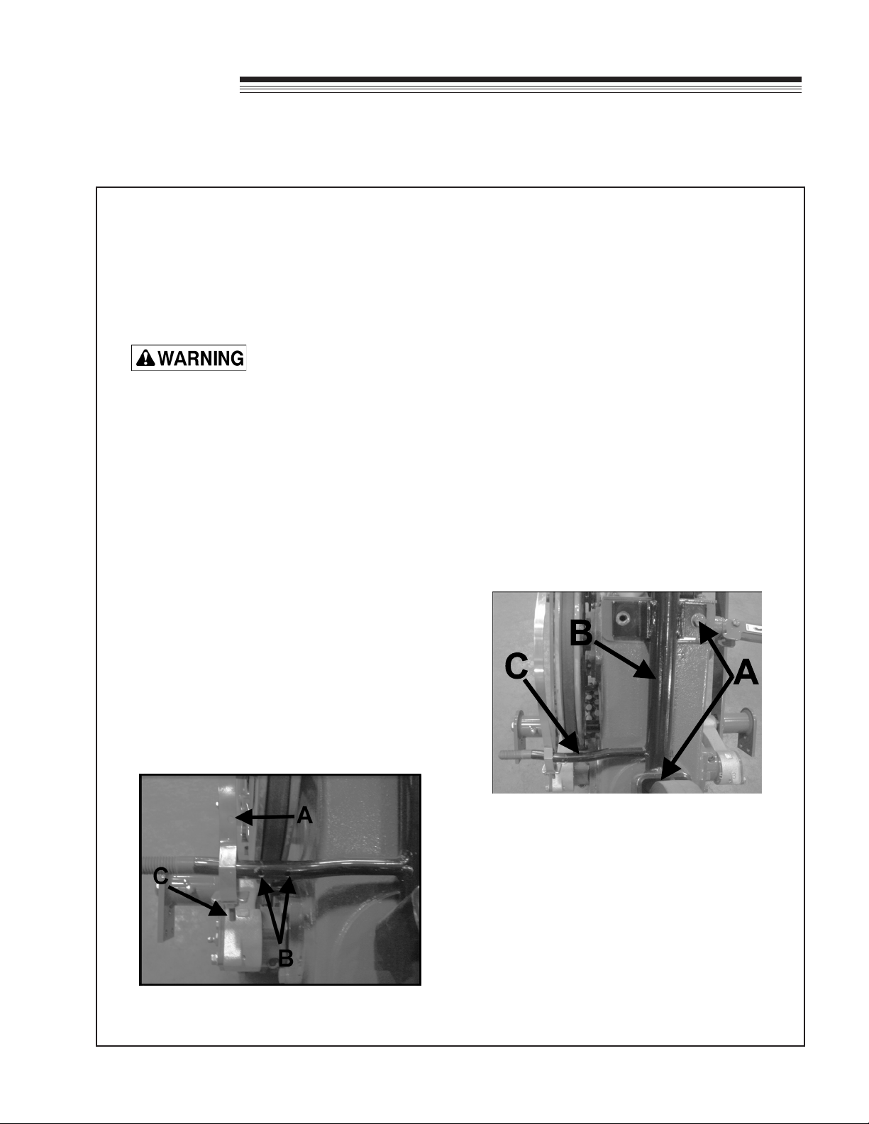
6. Slide adjustment end of brake band over the
guard support rod as shown in Figure 1.
FIGURE 1
A. Brake Band
B. Cotter Pin Holes
C. Adjustment Screw
7. Insert one cotter pin on each side of brake band,
using the two cotter pin holes shown in Figure
1. BE SURE the heads of the cotter pins are
on the pulley side of the support rod to prevent
interference between cotter pin and belt.
NOTICE
To prevent loss of gear lube from bottom hole in
gear case, tip unit forward until lifting handle on
front of unit is resting on the ground.
8. Remove and retain the upper two screws and
lockwashers from the rear of the gear case.
Loosen the lower screw in the slot behind the
wheel far enough to allow the handle bar to slide
behind the screw and washer. Figure 2.
FIGURE 2
A. Crankcase Screws
B. Handlebar Support
C. Guard Support Rod
9a. Apply Permatex gasket compound or an
equivalent to the three screws in step 8.
6
Jr.
Sodcutter
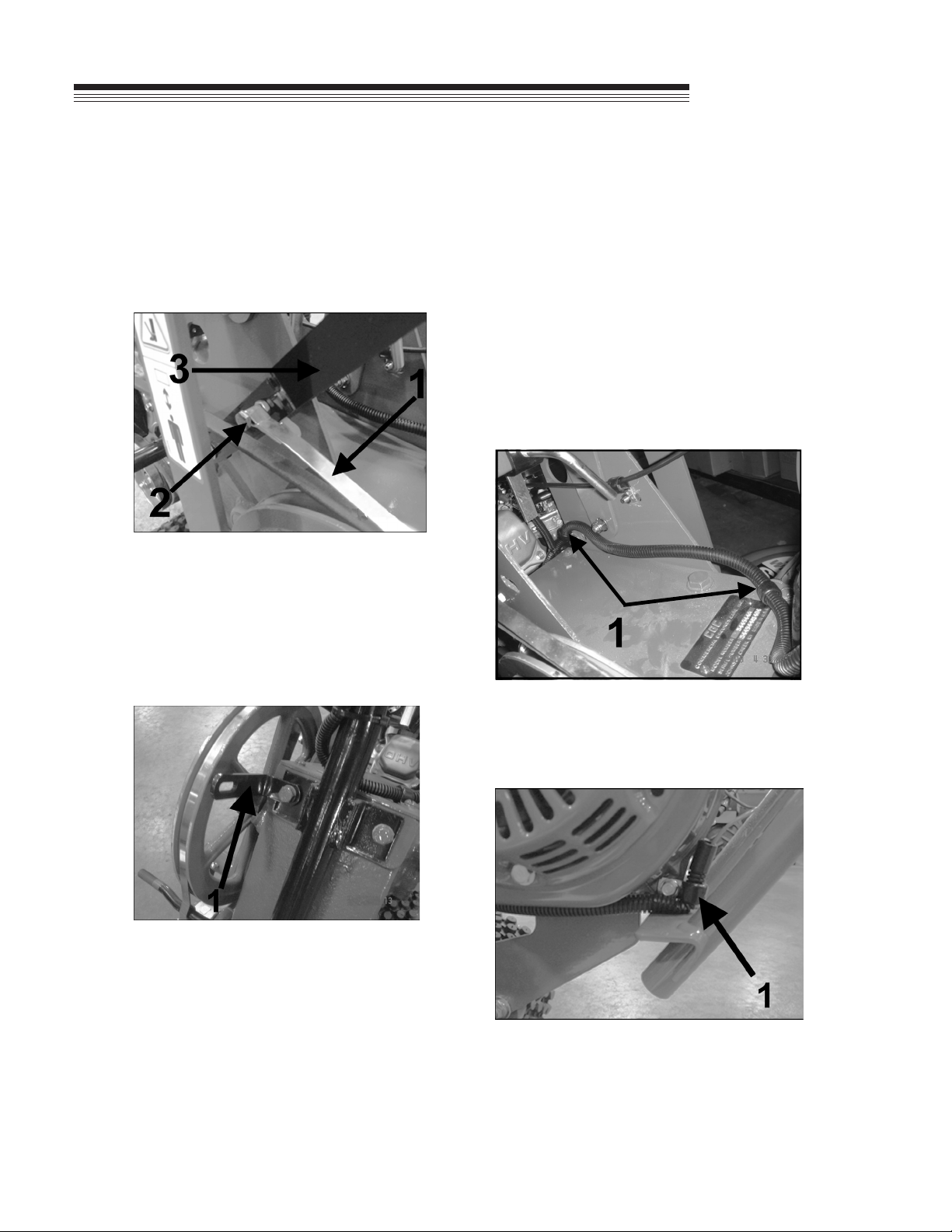
9b. NOTE: in this step, it is necessary to do three
things at one time.
1. The clevis assembly must be positioned just
to the right side of the belt, near the belt idler
arm.
Figure 3.
FIGURE 3
1. Brake Band
2. 1/4-20 Screw
3. Clevis
2. The brake band is positioned over the belt in
the large pulley groove. Figure 4.
FIGURE 4
1. "L" Bracket
3. The handle support is positioned, in the
bottom slot behind wheel, Figure 2, and then the
upper two bolts are attached with the "L" bracket
in the left hole. Figure 4. BE SURE the slotted
side of the "L" brackets is facing toward the large
pulley.
10. Connect the at end of the clevis assembly to the
idler arm as shown in Figure 3. The hardware
needed is on the clevis assembly. This should
pivot freely after it is tightened.
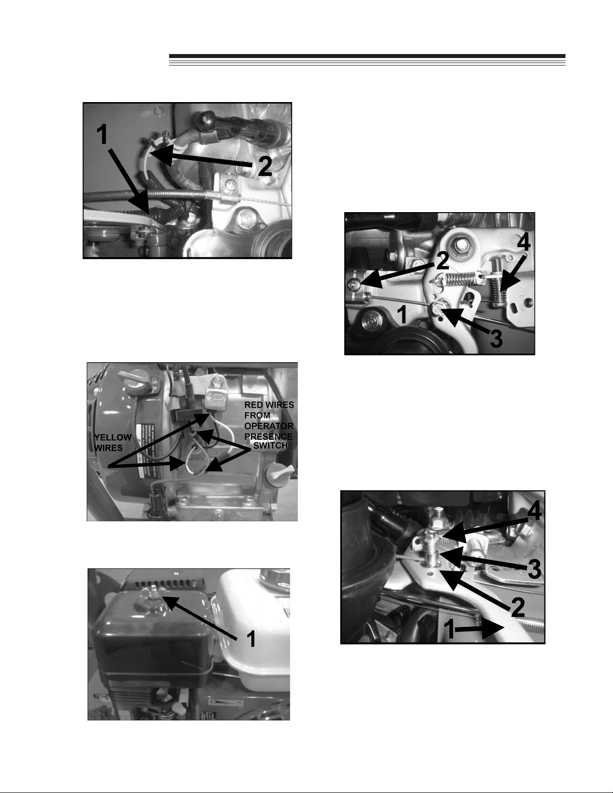
11. Route convoluted tubing from the control panel to
the front of the engine and attach at three points
with clips shown in Fiugre 5 and 6. Route wiring
and cable on the inside of the bracket. Route
convoluted tubing next to the hour meter wire
ty-rap together below the clip on the convoluted
tubing. Figure 7.
FIGURE 5
1. Tubing Clips
FIGURE 6
1. Tubing Clip
SET-UP
7
Jr.
Sodcutter
FIGURE 7
1. Convoluted Tubing
2. Hour Meter Wire
12. Connect red wire with male connector from
convoluted harness to the black female
connector on the front of the engine. Figure 8.
FIGURE 8
13. Loosen and remove wing nut securing air cleaner
cover. Remove cover and element to allow
access to the throttle. Figure 9.
1. Wing nut on Engine
14. Route the throttle cable on the inside of the
bracket. See Figure 5.
15. Route the throttle cable through the throttle
bracket as shown in Figure 10. The cable end
shoulder should be positioned as shown against
the end of the throttle bracket. Tighten down
throttle bracket making sure not to overtighten.
FIGURE 10
1. Throttle Cable
2. Throttle Bracket
3. Swivel
4. Throttle Stop Screw
16. The swivel needs to be inserted up through the
bottom of the engine throttle lever, the swivel
washer goes on and then the swivel screw.
Figure 11.
FIGURE 11
1. Throttle Lever
2. Swivel Washer
3. Swivel
4. Swivel Screw
SET-UP

8
Jr.
Sodcutter
17. Move throttle control on control panel to low idle
speed position while inserting cable end through
the swivel. See Figure 11.
18. Rotate engine throttle to high idle speed posiiton.
Move throttle control to high idle spped. Tighten
swivel screw to secure cable.
DO NOT overtighten cable stop.
19. Pull throttle control on panel back to low idle,
then push back to high idle.
20. If the engine throttle lever is not contacting the
end of the throttle stop screw, the swivel screw
must be loosened and the throttle cable wire
pulled through the cable stop further. Re-tighten
the swivel screw. Recheck to ensure the throttle
lever is contacting the end of the throttle screw, if
not, repeat.
21. Re-install the air cleaner element and cover.
Secure with the original wing nuts.
22. Use wire ties to secure convoluted tubing to
handlebar support. Figure 12.
FIGURE 12
1. Wire Ties
23. Pull the clutch control lever back to the
disengaged position. Adjust brake band by
turning the adjusting screw at the bottom of the
brake band with an allen wrench. Adjustment
should be snug enough but not too tight to cause
smoking of the drive belt. Install locking nut to
hold the brake band adjustment in place.
24. If brake band cannot be adjusted, reposition
engine. Slot on engine plate should be showing
7/32" to 1/4". See Figure 13.
FIGURE 13
25. Install one (1) 1/2-13 angelock nut (ange side
towards the outside of the unit) onto the guard
support rod before guard is reinstalled. (the
guard support rod is shown in Figure 2.
26. Reinstall guard onto side of unit using original
hardware. Secure "L" bracket to guard using
5/16-18 X 5/8" ange bolt and ange nut.
27. Insert two (2) 15 1/2" (394mm) cable ties through
the holes in the literature mounting plate. Figure
14. Secure literature tube using the large cable
ties.
FIGURE 14
1. Literature Mounting Plate
28. Attach the cutting blade using six (6) 5/16-24
X 1" grade 8 screws, lockwashers and nuts.
Torque attaching hardware to 30ft/lbs. (40.7 Nm)
USE ONLY the special grade 8 cap screws provided.
Screws below grade 8 will not withstand the
recommended torque requirements.
29. Install one (1) 1/2" angelock nut to the guard
support rod to complete the guard installation
from step 26.
SET-UP

9
Jr.
Sodcutter
CONTROLS
JR SODCUTTER CONTROLS
Clutch Control Lever - A
Engages or releases drive belt and applies brake
action to drive belt when pulled FIRMLY to rear.
Throttle Control - B
Speeds up or slows down the engine.
Engine Switch
Turn to "ON" position to start engine. Turn to "OFF"
position to stop engine.
Operator Presence Control - C
With clutch control engaged, engine will stop if
operator presence lever is not depressed.
Blade Depth Control Lever - D
Raises or lowers cutting blade.
Blade Depth Control Locking Lever - E
Locking lever holds blade depth control in desired
position.
Blade Angle Locking Lever - F
Adjusts cutting angle of blade.
Depth Gauge - G
Allows resetting of blade depth to the previous
cutting height.
Hour Meter - H Shows how many hours that the
engine has run. The far right digit is tenths of an
hour (1/10).
- The wire from the hour meter is wrapped around
the spark plug wire four (4) turns and secured with
Ty-raps.

10
Jr.
Sodcutter
CONTROLS
JR SODCUTTER CONTROLS
Blade (H) and Wheel (J) Shifter Handles : Engage
or disengage blade for cutting and gears for driving
Sodcutter.
"DISENGAGED" "ENGAGED"
SHIFTER HANDLE
GEAR
CASE
GEAR
CASE
SHIFTER

11
Jr.
Sodcutter
OPERATION
PRE-OPERATION CHECK
1. Visually check all moving parts and all fasteners.
If loose or broken, tighten or replace. Check
belt for fraying, wear and proper adjustment (see
SERVICE section).
2. Lubricate all lubrication ttings before each days
use or after every eight hours of operation (see
SERVICE section).
3. Check the engine crankcase oil level with the
engine resting in a level position. Add oil if
necessary.
4. Check the gear case oil level. Add oil if
necessary.
5. Check the air lter. Replace if necessary.
6. Sharpen cutting blade (see SERVICE section).
7. Follow the engine manufacturer's
recommendations for the correct type and
amount of oil. Fill the fuel tank according to the
engine manufacturer's specications.
Gasoline is extremely ammable and highly
explosive under certain conditions. Always stop
the engine and do not smoke or allow open
ames or sparks when refueling. BE SURE to
install fuel cap after refueling.
Do not ll containers in a vehicle or on a truck or
trailer bed with a plastic liner. Fill containers on
the ground away from the vehicle.
Refuel equipment on the ground. If equipment
must be fueled on a truck or trailer, refuel from
a portable container rather than a dispenser
nozzle.
Keep the dispenser nozzle in contact with the rim
of the fuel tank or container opening until fueling
is complete. Do not use a nozzle lock-open
device.
NEVER start or run the engine inside where
exhaust fumes can collect. Carbon monoxide
present in the exhaust is an odorless and deadly
gas.
DO NOT operate equipment without shields in
place. DO NOT make adjustments or perform
any maintenance while the engine is running.
Before operating, check the area and remove
any object which may present a safety hazard or
damage the equipment.
STARTING ENGINE
1. Be sure gas is turned on. Check Shut-off valve
located on the bottom of the fuel tank
2. Place all controls in "Disengaged" position.
3. Put Throttle lever at half speed.
4. Turn engine switch to "ON" position.
5. Pull recoil starter, and choke as required to start
engine. Allow engine to warm up.
MOVING THE JR SODCUTTER
To move unit without running blade :
1. Place blade shifter handle Hin "disengaged"
position (handle will point straight out from unit).
2. Set engine speed at slow speed.
3. Engage drive shifter handle.
4. Depress operator presence control.
5. Engage clutch control lever.
6. Adjust throttle to desired walking speed.
To move unit without running engine:
1. Put drive shifter handle and clutch control lever in
"Disengaged" position.
To transport the unit:
1. When transporting unit on trailer or truck, shut fuel
vavle "OFF" beneath fuel tank.
CUTTING SOD
1. Engage drive wheel shifter handle.
2. Engage blade shifter handle.
3. Standing on the right side of the unit, lift handle
with left hand, and lower blade to preset depth
with right hand. Tighten the locking lever.
4. Adjust throttle to full speed.
5. Push clutch lever forward and lower handle.
6. After cutting a short distance, stop unit and check
thickness of sod. Adjust if necessary.
7. At end of each cutting pass, lift up on handle to
clear cutting blade from sod, retard throttle and
turn Jr. Sodcutter around for return pass.

12
Jr.
Sodcutter
SERVICE
When replacement parts are required, use
genuine CGC, INC. parts or parts with equivalent
characteristics, including type, strength and
material. Failure to do so may result in product
malfunction and possible injury to the operator
and/or bystanders.
Carbon monoxide present in the exhaust is an
odorless and deadly gas. Never start or run the
engine inside where exhaust fumes can collect.
Provide enough fresh air to keep fumes from
getting too strong.
Any warning decal that becomes illegible should
be replaced immediately.
840697
STOP engine and disconnect spark plug wire
before servicing or making adjustments to unit.
The preceding decal shows what could happen
if the engine is not stopped or disabled before
removing safety covers. Hands may become
entangled in moving belts, gears, chains or other
parts.
Use adequate lifting device (i.e., hoist, fork lift,
etc.) to raise unit.
Use adequate supports when unit is raised for
servicing.
Wear protective eye equipment when using
hammers, chisels and punches.
BLADE SHARPENING
1. Hand le bottom blade at 45O angle until no at
remains.
2. To keep cutting edge less than 1/16" on 45O
angle, grind milled surface back at 15Oto less
than 1/16".
3. Hand le side blades at 45O until no at remains.
4. To keep cutting edge less than 1/16" on 45O
angle, grind milled surface back at 15Oto less
than 1/16".
THIS
1/16"
Maximum
45
O
15
O
FILE
DIRECTION
SURFACE
SMOOTH
(No Burrs)
BOTTOM BLADE
MILLED
EDGE
FILE
DIRECTION
1/16" MAX
THIS SURFACE SMOOTH
(No Burrs)
FILE
DIRECTION
SIDE BLADE
13
Jr.
Sodcutter
SERVICE
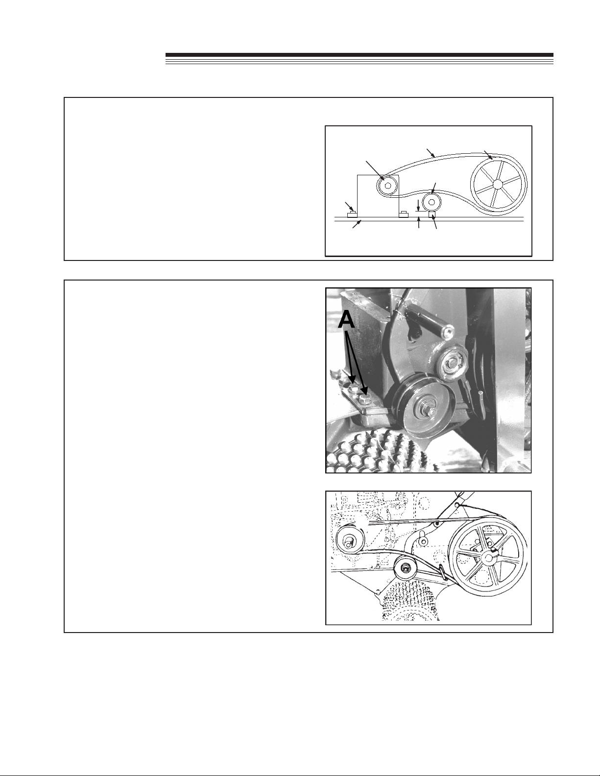
DRIVE BELT ADJUSTMENT
Keep belt free of oil and dirt, and adjusted to
proper tension at all times.
Belt tension is adjusted by loosening four (4)
engine mounting bolts and shifting engine on the
base.
The belt should be taut when the clutch lever is
pushed forward (engaged) and the idler wheel is
1" (25.4 mm) from the engine mount plate.
ENGINE
ENGINE
BOLT
ENGINE
PULLEY
BLOCK
ENGINE
MOUNT PLATE
1" (25.4 mm)
IDLER
PULLEY
BELT DRIVE
PULLEY
DRIVE BELT REPLACEMENT
1. Remove shield on left side of unit.
2. Remove nut securing brake band to clutch
control rod.
3. Remove cotter pin on outside of guard support
rod and move brake band over to nut on rod.
4. Loosen two bolts Asecuring belt guide to
provide clearance when removing belt.
5. Install new belt in reverse procedure. Route the
belt as shown.

14
Jr.
Sodcutter
SERVICE
DRIVE CHAIN REMOVAL
1. Raise unit, place on adequate supports and
remove belt guard.
2. Remove four (4) screws securing cover.
3. Remove throttle cable from engine and lay
behind cam case.
4. Remove dipstick from cover.
5. Remove screw, at washer, nut and bushing from
right lower side of "H" frame.
6. Using a screwdriver, lift cover to break sealant
bond and remove cover.
7. Drain oil out of front cavity on case, and turn
drive wheels until master link is on top of
sprocket.
8. Remove master link and continue rotating drive
wheels until chain is off bottom sprocket.
9. Install new chain in reverse procedure. Clean
mating surfaces on case and cover. Apply 3M
Scotch Grip 847 or an equivalent adhesive to
case cover before installation.
BLADE DRIVE CHAIN REPLACEMENT
NOTE: To prevent small components from falling
down into oil cavities and causing damage
to unit, cover opening with clean rags,
cardboard, etc.
1. Follow steps 1 thru 6 in drive chain removal.
2. Remove bottom screw on bearing cage to drain
oil from rear cavity.
3. Rotate pulley shaft until master link is to front of
top sprocket. Remove master link.
4. Rotate blade drive shaft until chain is free.
5. Install new chain in reverse procedure. Use 3M
Scotch Grip 847 or an equivalent adhesive on
case cover and bearing retainer screw.

15
Jr.
Sodcutter
SERVICE
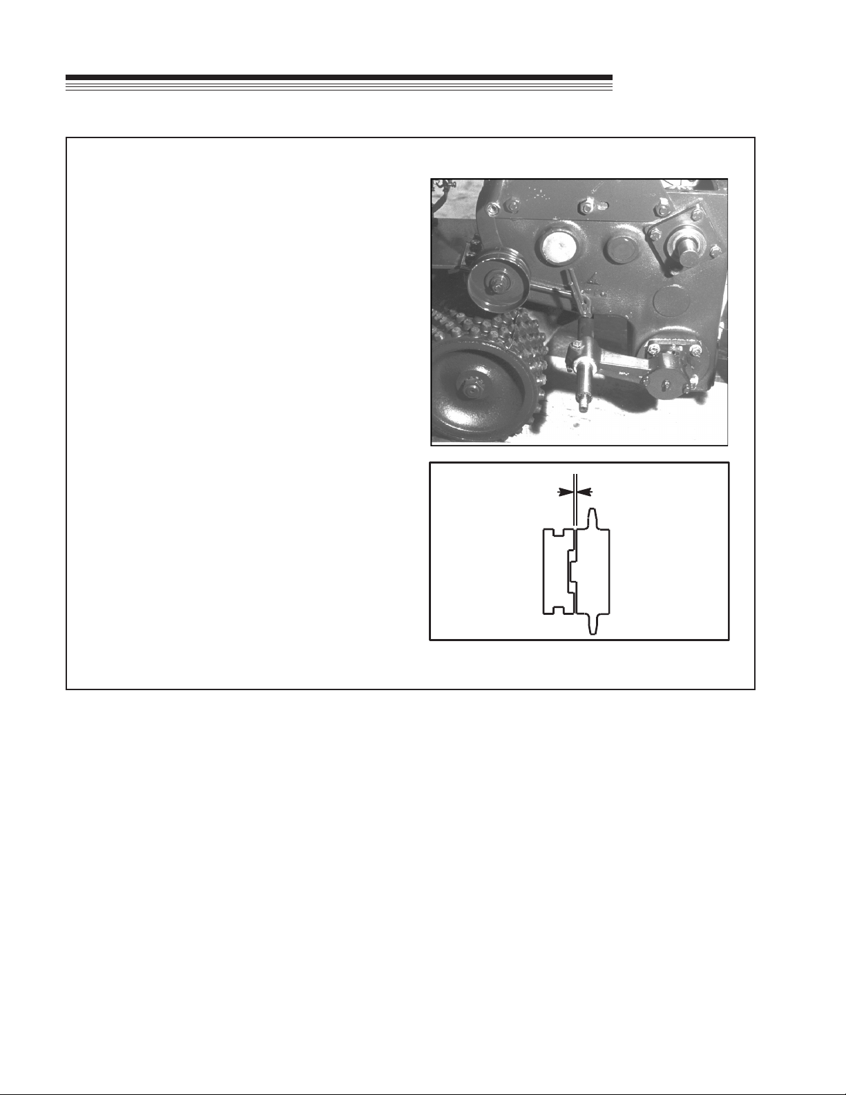
UPPER DRIVE SPROCKET & SHAFT
1. Remove drive chain according to steps 1 thru 6
in drive chain removal section.
2. Remove master link from chain. Chain does not
need to be removed from lower sprocket.
3. Remove drive shifter assembly from gear case.
4. Remove blade and side arms from pivot brackets
for easier access.
5. Remove plugs on both ends of shaft.
6. Remove snap rings Bfrom left bearing.
7. Using a punch and soft hammer (lead, leather,
etc.), drive shaft out left side of unit and remove
large gear.
8. Using a bearing puller or slide hammer, remove
bearing. Shaft is now removable through cam
case cover opening.
9. Dog clutch half is removable from gear by
removing snap ring.
10. Assemble in reverse procedure.
11. After installing blade shifter assembly, adjust
dog clutch to provide .015" (0.39 mm) clearance
between clutch faces, as shown.
12. Apply 3M Scotch Grip adhesive or an equivalent
to gear case cover before installation.
.015
(0.39 mm)
16
Jr.
Sodcutter
SERVICE
DRIVE WHEEL CHAIN SPROCKET SHAFT
1. Follow steps 1 thru 7 in drive chain removal
section.
2. Remove master link and remove chain from top
sprocket.
3. Remove both drive wheels and axle keys.
4. Remove seal in case and snap ring retaining
bearing in case.
5. Install axle nut on end of shaft, opposite the side
of snap ring previously removed.
6. Using a soft hammer (lead, brass, etc.), drive
shaft out of case. Sprocket can now be removed
by lifting up on chain.
7. Top sprocket and chain should be checked for
wear and replaced if necessary.
8. Reassemble in reverse procedure using new
seals and gaskets.
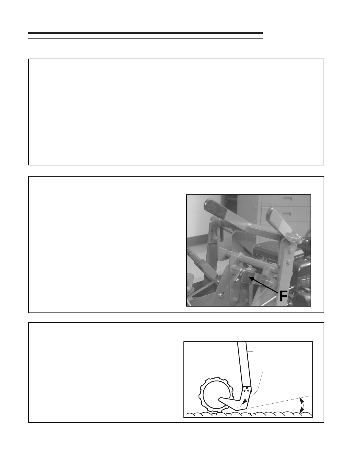
ADJUSTING BLADE ANGLE
1. Loosen blade angle control locking lever Fand
move H-frame forward or backward until blade is
at desired angle of pitch.
2. Tighten blade angle control locking lever F.
SIDE ARM
DRIVE
WHEEL
BLADE
BOTTOM
BLADE
ANGLE
(Pitch)
BLADE ANGLE (PITCH)
Under normal operating conditions, blade angle
is minimal (blade bottom is at). In extremely
hard soil or when cutting with a dull blade, the
blade may want to ride out of the ground. It may
then help to adjust blade angle downward (see
Adjusting Blade Angle above). A short trial run
will indicate which is the best blade angle.

17
Jr.
Sodcutter
SERVICE
ADJUSTING DEPTH OF CUT
1. Make a trial run in turf. Set depth to cut
approximately 3/4" of soil.
2. Loosen depth gauge handle. Adjust depth gauge
Gto contact bottom on depth control lever D.
3. Loosen depth control locking lever Eand lower
depth control Duntil it rests on depth gauge G.
4. Tighten depth control locking lever E.
NOTE: Numbers on depth gauge do not necessarily
represent thickness of sod being cut.
ADJUSTING OPERATOR PRESENCE CONTROL
1. To adjust operator presence cable, pull clutch
control handle Arearward as far as possible.
2. Press operator presence handle (right handlebar)
down as far as possible.
3. Adjust cable until the pivot arm Ccontacts the
arm extending from the operator presence switch
B.
4. Tighten cable clamp to secure cable. Check for
proper operation.
18
Jr.
Sodcutter
PULLEY SHAFT
1. Follow steps 1 thru 4 in belt replacement section
and steps 2 thru 6 in drive chain removal section.
2. Remove blade from unit and remove left side
arm.
3. Remove blade shifter assembly.
4. Turn pulley until master link is on top of sprocket.
Remove chain from top sprocket.
5. Remove belt pulley and key.
6. Remove four (4) bearing cage screws and pull
gears out left side of unit. Dog clutch and double
sprocket will slide off as shaft is removed.
7. To remove gear and bearing, remove snap ring,
slide gear off shaft and remove key. Remove
bearing snap ring and remove bearing.
8. Assemble in reverse procedure. After blade
shifter assembly is installed, adjust dog clutch
to provide .015" (0.39 mm) clearance between
clutch faces, as shown.
9. Apply 3M Scotch Grip 847 adhesive or equivalent
to gear case cover before installation.
SERVICE
.015
(0.39 mm)
Table of contents


