L10 User Manual 7
Do not screw the spikes in too far at this point or they will protrude from the feet and potentially damage
the supporting surface. Do not replace the top-caps yet.
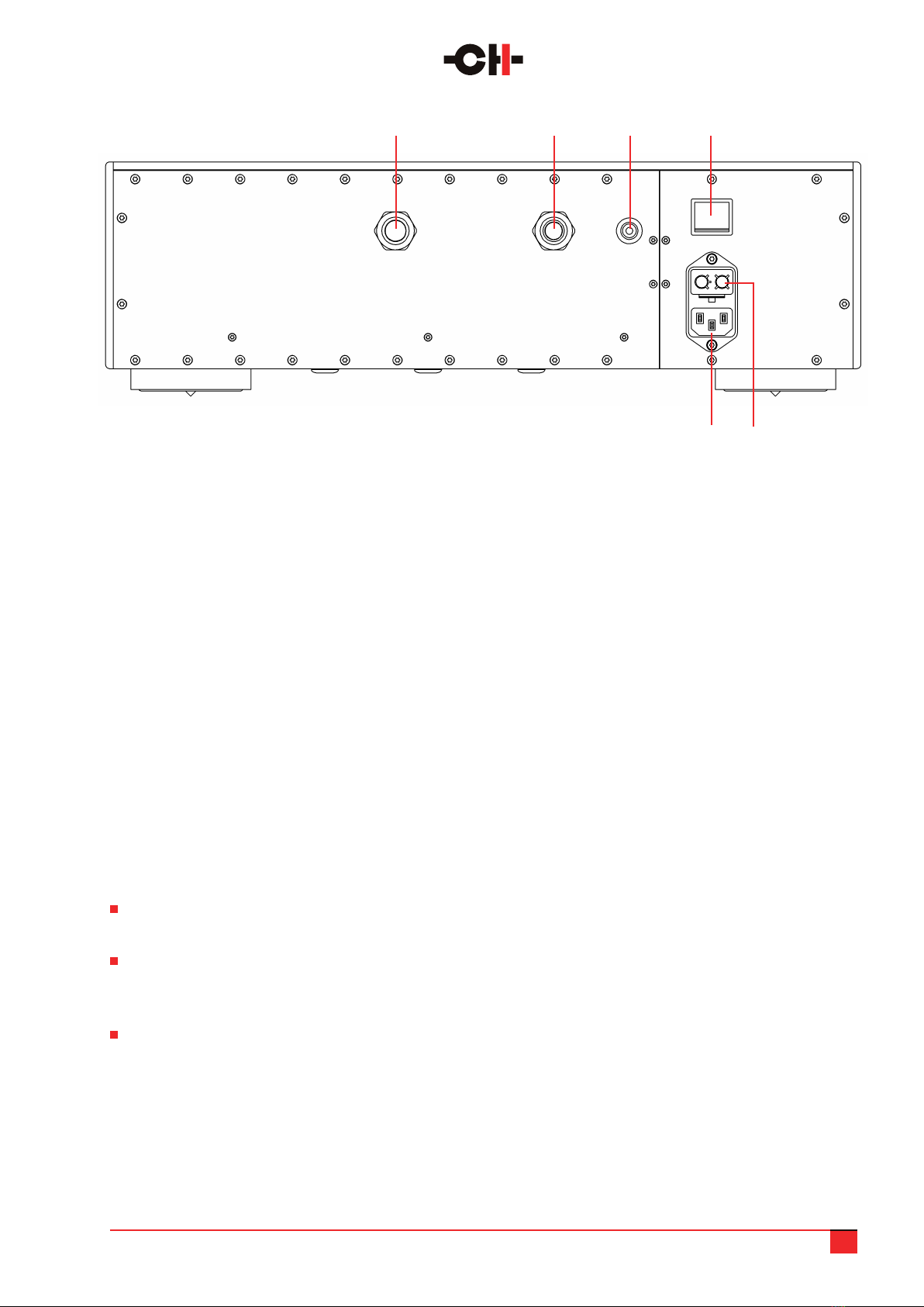
Check that the voltage selector on the L10 power supply unit is set to the correct local voltage and that the
power switch is off (the 0 side depressed).
Now you are ready to place the units. Each chassis is heavy and the feet are tted with rubber rings to protect
the supporting surface, which makes it hard to slide the units. Having a partner to lift and help place each
chassis will make things considerably easier.
Place the power supply rst, carefully planning the path to be taken by the two umbilicals before positioning
the unit.
Gently pull the umbilicals into position to be connected to the audio chassis, noting which is which thanks
to the color identication rings.
Move the audio unit as close as possible to the rack/support so that you can connect the umbilicals before
moving it back into position. Connect the left umbilical to the left input socket and the right umbilical to the
right input socket. The plugs on the umbilicals will only connect in one position, so turn the connector in the
socket until you feel it engage and then gently push it home until you hear a locking sound.
DO NOT force the umbilical connectors into the sockets.
This will risk damaging the connecting pins and disable your L10.
If you feel resistance when you insert the connector, check that you are trying to connect the proper pairs
of umbilicals and connectors together. Please note that the two connectors have the same diameter but
a different number of pins, so it is not possible to plug an umbilical in the wrong connector.
Each L10 chassis is supplied with a set of four support discs. These have a groove machined in the upper face
that ts over the rubber ring in the underside of each foot. Lift each corner of the chassis in turn and position
the disc beneath each foot. The groove that interfaces with the rubber ring will ensure that the footer disc
stays in place if you slide the unit.
As well as making the units easier to position, the support discs can also offer a superior interface between
the grounding spikes and the supporting surface. The spikes are designed to drain internally generated
energy away from sensitive circuitry and into a dispersive support structure, but if the supporting surface
is extremely hard or forms an impedance mismatch with the spike tips, the material and footprint of the
support discs can function as a lossy mechanical buffer, easing the passage of mechanical energy out of the
unit. As a rule, the support discs work well with very hard surfaces, but results will vary with system and
supporting surface. Once set up and warmed up, compare the sound of the unit(s) with and without the discs
in place.
Use the red screwdriver to wind down each of the four spikes until they touch the surface (or disc)
underneath. You will feel a slight resistance due to the chassis’ weight. Then turn each spike by the same
amount, for instance one more full turn. This should ensure that the load is evenly applied on all four spikes.
It is worth using a spirit level to ensure that the L10 units are perfectly level. If they are not at this point of the
setup, adjust the spikes with the screwdriver. Once this is done, simply check that all four spikes show the same
resistance to turning. This means that the spikes are rigidly coupled to the supporting discs and equally loaded.
Replace the top caps. Their magnetic coupling will hold them in place.