installation
The SH 12 is supplied in two cartons, one containing the
heater, the other containing the flue set and shower fittings.
INSTALLING THE BALANCED FLUE
The standard flue set is suitable for walls having athickness
of 75 mm (3 in) to 355 mm (14 in). A flue set for wall
thicknesses up to 610 mm (24 in) is available to special
order.
Detailed recommendations for flueing are given in BS
5440 : 1. The following notes are intended to give general
guidance.
The shower heater must be installed so that the flue ter-
minal is exposed to the external air.
Termination should be on a clear expanse of wall ; the
terminal being preferably not lessthan 600 mm (2 ft) away
from a corner, recessor projection.
DO NOT install the terminal :
a) within 300 mm (1 ft), measured vertically, from the
bottom of an openable window, air vent or any other
ventilation opening.
b) within 300 mm (1 ft) above adjacent ground level.
C)
within 600 mm (2 ft) of any surface facing the terminal.
d) immediately beneath eavesor abalcony.
Where the lowest part of the terminal is less than 2 m
(6.6 ft) above the level of any ground, balcony, flat roof or
place to which any person hasaccessand which adjoins the
wall in which the terminal is situated, the terminal must be
protected by aguard of durable material. (A terminal guard
may be obtained from Chaffoteaux Limited).
The air inlet, products outlet duct and the terminal of the
heater must be not closer than 50 mm (2 in) to combustible
material. Detailed recommendations on protection of
combustible material aregiven in BS 5440 : 1.
Preparing the Wall
The heater should be installed on a wah of flat noncom-
bustible material that will not reverberate.
Whatever the
thickness of the wall, make a hole 240 mm (9.5 ins)
wide x 125 mm (4.9 ins) high. If
the hole is cut
accurately
there is no need to line it, since the wall liner will seal
off the cavity.
A II$&N,M clearance of 75 mm (3.0 in) should be left
above the top of the wall opening. No allowance is neces-
sary at the side of the heater. For dimensions see Dia-
gramPage2.
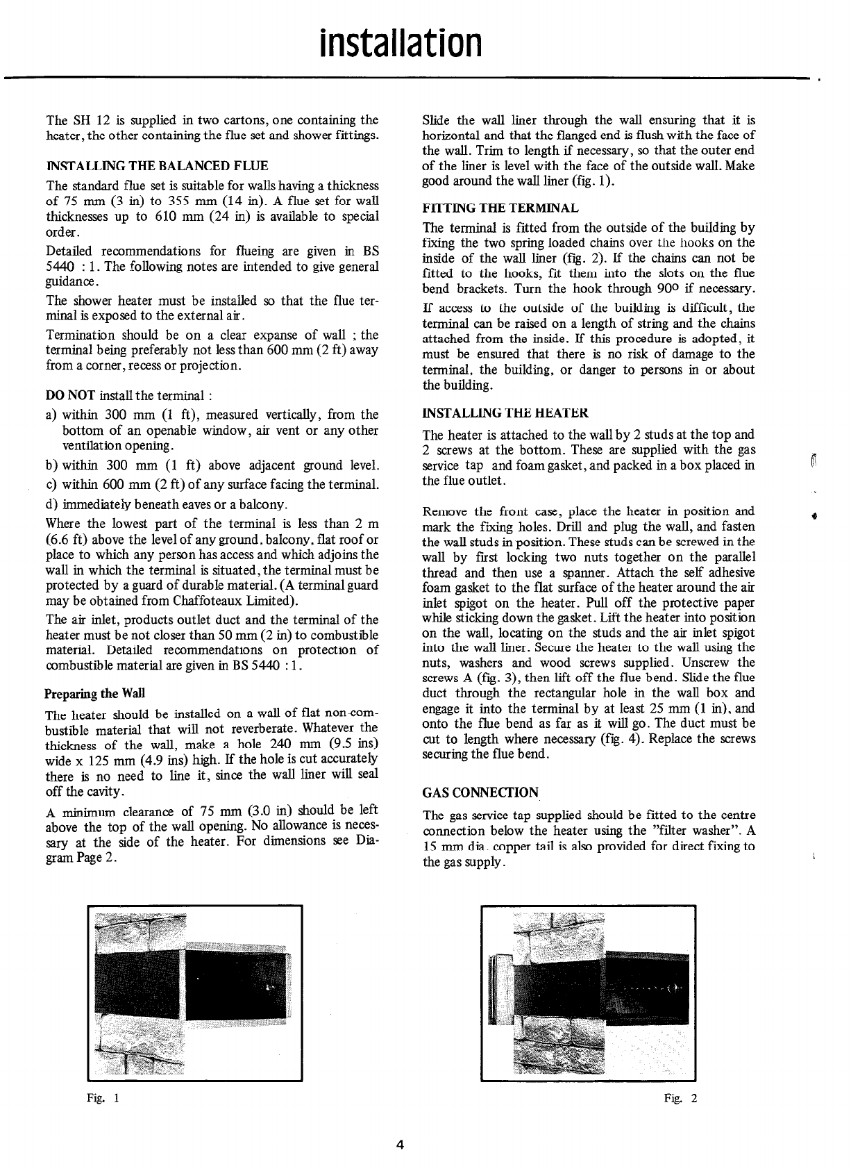
Slide the wall liner through the wall ensuring that it is
horizontal and that the flanged end is flush with the face of
the wall. Trim to length if necessary, so that the outer end
of the liner is level with the face of the outside wall. Make
good around the wall liner (fig. 1).
FITTING THE TERMINAL
The terminal is fitted from the outside of the building by
fixing the two spring loaded chains over the hooks on the
inside of the wall liner (fig. 2). If the chains can not be
fitted to the hooks, fit them into the slots on the flue
bend brackets. Turn the hook through 900 if necessary.
If access to the outside of the building is difficult, the
terminal can be raised on a length of string and the chains
attached from the inside. If this procedure is adopted, it
must be ensured that there is no risk of damage to the
terminal, the building, or danger to persons in or about
the building.
INSTALLING THE HEATER
The heater is attached to the wall by 2 studs at the top and
2 screws at the bottom. These are supplied with the gas
service tap and foam gasket, and packed in abox placed in
the flue outlet.
Remove the front case, place the heater in position and
mark the fixing holes. Drill and plug the wall, and fasten
the wall studs in position. These studs can be screwedin the
wall by fast locking two nuts together on the parallel
thread and then use a spanner. Attach the self adhesive
foam gasket to the flat surface of the heater around the air
inlet spigot on the heater. Pull off the protective paper
while sticking down the gasket. Lift the heater into position
on the wall, locating on the studs and the air inlet spigot
into the wall liner. Securethe heater to the wall using the
nuts, washers and wood screws supplied. Unscrew the
screws A (frg. 3), then lift off the flue bend. Slide the flue
duct through the rectangular hole in the wall box and
engage it into the terminal by at least 25 mm (1 in), and
onto the flue bend as far as it will go. The duct must be
cut to length where necessary(fig. 4). Replace the screws
securing the flue bend.
GAS CONNECTION
The gas service tap supplied should be fitted to the centre
connection below the heater using the “filter washer”. A
15 mm dia. copper tail is also provided for direct fixing to
the gassupply
Fig. I
4
Fig.
2