Chamberlain CAPXSTK User manual

TRIM PLATES AND HOOD
MODELS: CAPXSTK, CAPXSTKPL, AND CAPXSHOOD
INTRODUCTION
The CAPXSTK and CAPXSTKPL are available to conceal the replacement of
an existing telephone entry system or buzzer with a CAPXS. The CAPXSTK
is a standard trim plate, and the CAPXSTKPL provides a postal lock
provision for buildings that require the integration of a postal lock.
CAPXSTKPL INSTALLATION
CARTON INVENTORY
Trim Panel, Postal Lock Cover, (4) #10 Phillips Screw and Hex Nut, (4)
#8T20 Torx Screw
ADDITIONAL ITEMS YOU MAY NEED
Silicone Sealant, Phillips Screwdriver, T20 Screw Driver/Bit, Mounting
Hardware per CAPXS Installation manual, Postal Lock Device (provided by
USPS)
POSTAL LOCK INSTALLATION
1. Fasten Postal Lock to Trim Panel using #10 Phillips screws and hex
nuts provided. (See Figure 1)
2. Verify switch is depressed while in the locked position. Adjust as
needed. (See inset of Figure 1)
3. Position Cover over Postal Lock. Make sure that sealing gasket is
properly seated. (See Figure 2)
4. Secure the Cover over the Postal Lock from the rear using #8 T20
Screws.
5. Make sure Postal Lock Switch wires are routed through the wire egress
opening. (See inset of Figure 1)
6. Fasten to the gang box or wall through the Mounting Bracket and Trim
Panel using the hardware specified in the CAPXS Installation Manual.
(See Figure 3)
7. Silicone Sealant can be used on the rear edge of the trim panel or along
the mating edge after installation.
8. Follow CAPXS manual to finish the installation. (See Figure 4)
WARNING: This product can expose you to chemicals
including lead, which are known to the State of California to
cause cancer or birth defects or other reproductive harm. For
more information go to www.P65Warnings.ca.gov.
Figure 1
Figure 3
Figure 2
Figure 4
CAPXSTKPL
Postal Lock
(not provided)
Cover
CAPXS
Bracket

CAPXSTK INSTALLATION
CARTON INVENTORY
Trim panel
ADDITIONAL ITEMS YOU MAY NEED
Silicone Sealant, Mounting Hardware per CAPXS Installation manual
TRIM PANEL INSTALLATION
1. Place the Mounting Bracket on the Trim Panel.
2. Fasten to the gang box or wall through the Mounting Bracket and Trim
Panel using the hardware specified in the CAPXS Installation Manual.
(See Figure 5)
3. Silicone Sealant can be used on the rear edge of the trim panel or along
the mating edge after installation.
4. Follow CAPXS manual to finish the installation.
CAPXSHOOD INSTALLATION
CARTON INVENTORY
Hood, (2) T20 Torx Screw
ADDITIONAL ITEMS YOU MAY NEED
T20 Screw Driver/Bit
HOOD INSTALLATION
The CAPXS Hood can be installed on CAPXS during a new install, or it can
be installed on a existing installation.
1. If installing on an existing installation, remove the side screws on the
CAPXS. Discard these screws. (See Figure 6)
For new installations proceed to step 2.
2. For new installation, follow CAPXS manual for installation of the
CAPXS.
3. Place the CAPXS Hood. The side detent will fit into the Mounting
Bracket recesses. (See Figure 7)
4. Once both sides are seated, using new screws provided with
CAPXSHOOD, tighten using a T20 Torx Screw Driver. (See Figure 8)
Figure 5
CAPXSTK
Figure 8
CAPXSHOOD
Figure 6
Figure 7
114-5813-000
© 2022, LiftMaster
All Rights Reserved
Tous droits réservés
Todos los derechos reservados
LiftMaster
300 Windsor Drive
Oak Brook, IL 60523
LiftMaster.com


PLAQUES DE GARNITURE ET CAPOT
MODÈLES: CAPXSTK, CAPXSTKPL ET CAPXSHOOD
INTRODUCTION
Les CAPXSTK et CAPXSTKPL sont disponibles pour dissimuler le
remplacement d’un système d’entrée téléphonique ou d’une sonnette
existant par un CAPXS. Le CAPXSTK est une plaque de garniture standard,
et le CAPXSTKPL est compatible à une serrure postale pour les bâtiments
qui nécessitent l’intégration d’une serrure postale.
INSTALLATION DU CAPXSTKPL
INVENTAIRE DU CARTON
Panneau de garniture, couvercle de serrure postale, (4) vis cruciforme
n°10 et écrou hexagonal, (4) vis Torx T20 #8
ARTICLES SUPPLÉMENTAIRES DONT VOUS
POURRIEZ AVOIR BESOIN
Mastic silicone, tournevis cruciforme, tournevis/embout T20, matériel de
montage conformément au manuel d’installation du CAPXS, dispositif de
serrure postale (fourni par USPS)
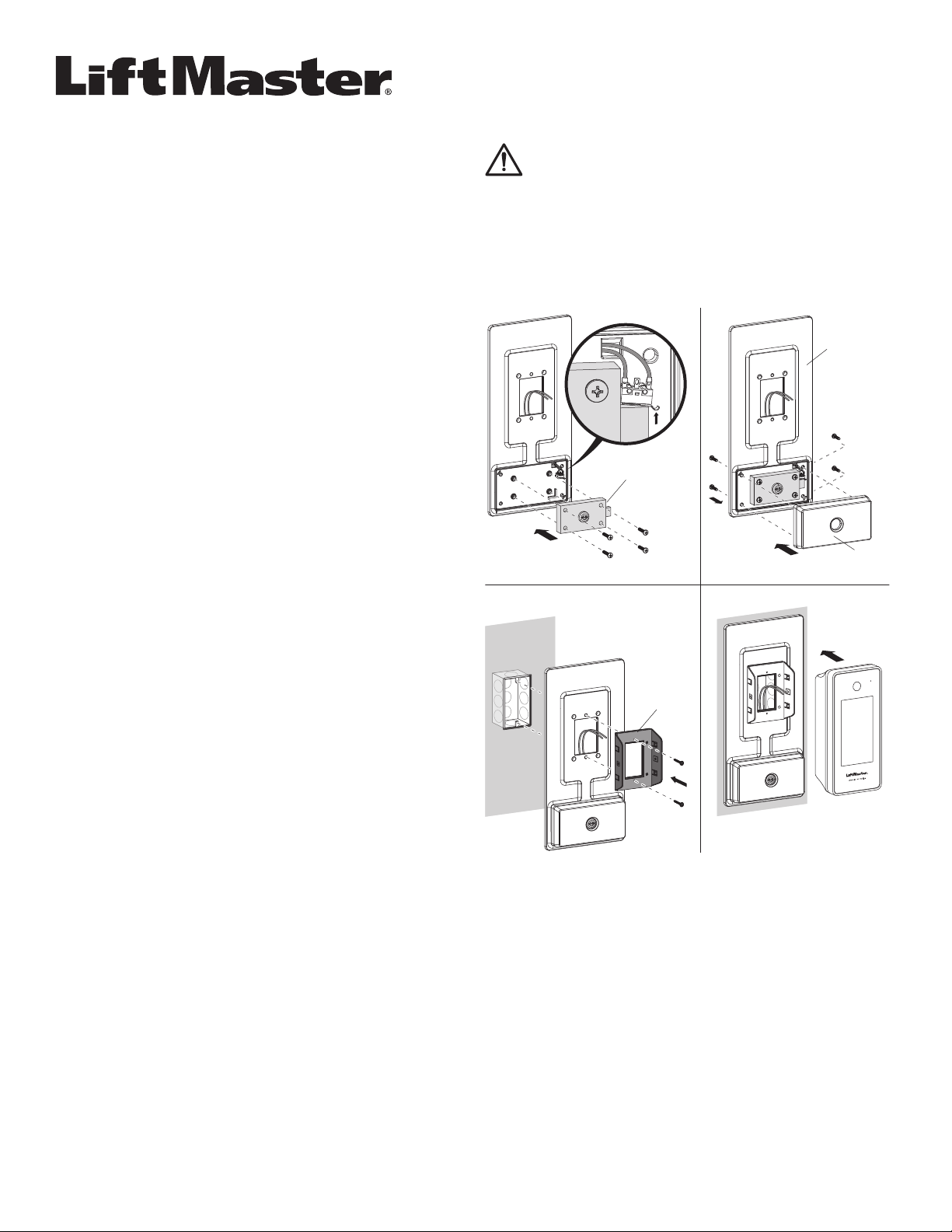
INSTALLATION DE LA SERRURE POSTALE
1. Fixez la serrure postale au panneau de garniture à l’aide des vis
cruciforme n°10 et des écrous hexagonaux fournis. (Voir figure 1)
2. Vérifiez que le commutateur est enfoncé en position verrouillée. Ajustez
si nécessaire. (Voir encadré de la figure 1)
3. Placez le couvercle sur la serrure postale. Assurez-vous que le joint
d’étanchéité est bien en place. (Voir figure 2)
4. Fixez le couvercle sur le verrou postal par l’arrière à l’aide de vis T20
n°8.
5. Assurez-vous que les fils de l’interrupteur de serrure postale sont
acheminés par l’ouverture de sortie des fils. (Voir encadré de la figure 1)
6. Fixez à la boîte de commande ou au mur en passant par le support de
montage et le panneau d’habillage à l’aide du matériel spécifié dans le
manuel d’installation du CAPXS. (Voir figure 3)
7. Le mastic silicone peut être utilisé sur le bord arrière du panneau de
garniture ou le long du bord d’accouplement après l’installation.
8. Suivez le manuel du CAPXS pour terminer l’installation. (Voir figure 4)
Figure 1
Figure 3
Figure 2
Figure 4
CAPXSTKPL
Serrure
postale (non
fournie)
Couvercle
Support
du CAPXS
AVERTISSEMENT: Ce produit peut vous exposer à des produits
chimiques, dont le plomb, qui sont reconnus par l’État de Californie
comme provoquant le cancer, des malformations congénitales
ou d’autres problèmes de reproduction. Pour plus d’information,
visitez www.P65Warnings.ca.gov.

INSTALLATION DU CAPXSTK
INVENTAIRE DU CARTON
Panneau de garniture
ARTICLES SUPPLÉMENTAIRES DONT VOUS POUR-
RIEZ AVOIR BESOIN
Joint en silicone, matériel de montage selon le manuel d’installation du
CAPXS
INSTALLATION DES PANNEAUX DE GARNITURE
1. Placez le support de montage sur le panneau de garniture.
2. Fixez à la boîte de commande ou au mur en passant par le support de
montage et le panneau d’habillage à l’aide du matériel spécifié dans le
manuel d’installation du CAPXS. (Voir figure 5)
3. Le mastic silicone peut être utilisé sur le bord arrière du panneau de
garniture ou le long du bord d’accouplement après l’installation.
4. Suivez le manuel du CAPXS pour terminer l’installation.
INSTALLATION DU CAPXSHOOD
INVENTAIRE DU CARTON
Capot, (2) vis Torx T20
ARTICLES SUPPLÉMENTAIRES DONT VOUS
POURRIEZ AVOIR BESOIN
Tournevis/embout T20
INSTALLATION DU CAPOT
Le capot du CAPXS peut être installé sur le CAPXS lors d’une nouvelle
installation, ou sur une installation existante.
1. En cas d’installation sur une installation existante, retirez les vis
latérales du CAPXS. Jetez ces vis. (Voir figure 6)
Pour les nouvelles installations, passez à l’étape 2.
2. Pour une nouvelle installation, suivez le manuel du CAPXS pour
l’installation du CAPXS.
3. Placez le capot du CAPXS. Le cliquet latéral s’insère dans les
évidements du support de montage. (Voir figure 7)
4. Une fois les deux côtés en place, serrez les nouvelles vis fournies avec
le CAPXSHOOD à l’aide d’un tournevis Torx T20. (Voir figure 8)
Figure 5
CAPXSTK
Figure 8
CAPXSHOOD
Figure 6
Figure 7
114-5813-000
© 20, LiftMaster
All Rights Reserved
Tous droits réservés
Todos los derechos reservados
LiftMaster
300 Windsor Drive
Oak Brook, IL 60523
LiftMaster.com


PLACAS DE AJUSTE Y CUBIERTA
MODELOS: CAPXSTK, CAPXSTKPL Y CABEZAL CAPXS
INTRODUCCIÓN
Los modelos CAPXSTK y CAPXSTKPL están disponibles para ocultar la
sustitución de un portero automático o un timbre existente por un CAPXS.
El modelo CAPXSTK es una placa de ajuste estándar y el CAPXSTKPL
tiene la función de cerradura postal para los edificios que requieren que
dicha cerradura se encuentre integrada.
INSTALACIÓN DE CAPXSTKPL
INVENTARIO EN LA CAJA
Panel de ajuste, cubierta de cerradura postal, (4) tornillos Phillips #10 y
tuerca hexagonal, (4) tornillos Torx #8T20
ARTÍCULOS ADICIONALES QUE PUEDE NECESITAR:
Sellador de silicona, destornillador Phillips, destornillador/broca T20,
herraje de montaje según el manual de instalación de CAPXS, dispositivo
de cerradura postal (proporcionado por USPS)
INSTALACIÓN DE LA CERRADURA POSTAL
1. Fije la cerradura postal al panel de ajuste mediante los tornillos Phillips
#10 y las tuercas hexagonales suministradas. (Vea la Figura 1)
2. Verifique que el interruptor esté presionado en la posición de bloqueo.
Ajuste si es necesario. (Vea el recuadro de la Figura 1)
3. Coloque la cubierta sobre la cerradura postal. Asegúrese de que la
junta de sellado esté bien asentada. (Vea la Figura 2)
4. Fije la cubierta sobre la cerradura postal desde la parte trasera con
tornillos T20 #8.
5. Asegúrese de que los cables del interruptor de la cerradura postal
pasen por la apertura de salida de los cables. (Vea el recuadro de la
Figura 1)
6. Sujetar a la caja de distribución o a la pared a través del soporte de
montaje y el panel de ajuste utilizando los accesorios especificados en
el manual de instalación de CAPXS. (Vea la Figura 3)
7. Se puede utilizar un sellador de silicona en el borde posterior del
panel de ajuste o a lo largo del borde de acoplamiento después de la
instalación.
8. Siga el manual de CAPXS para terminar la instalación. (Vea la Figura 4)
Figura 1
Figura 3
Figura 2
Figura 4
CAPXSTKPL
Cerradura
postal (no se
suministra)
Cubierta
Soporte
CAPXS
ADVERTENCIA: Con este producto, puede exponerse a sustancias
químicas, incluido el plomo, que el Estado de California reconoce
como causantes de cáncer o anomalías congénitas u otros
daños reproductivos. Para obtener más información, visite
www.P65Warnings.ca.gov.

INSTALACIÓN DE CAPXSTK
INVENTARIO EN LA CAJA
Panel de adorno
ARTÍCULOS ADICIONALES QUE PUEDE NECESITAR:
Sellador de silicona, herraje de montaje según el manual de instalación de
CAPXS
INSTALACIÓN DEL PANEL DE AJUSTE
1. Coloque el soporte de montaje en el panel de ajuste.
2. Sujetar a la caja de distribución o a la pared a través del soporte de
montaje y el panel de ajuste utilizando los accesorios especificados en
el manual de instalación de CAPXS. (Vea la Figura 5)
3. Se puede utilizar un sellador de silicona en el borde posterior del
panel de ajuste o a lo largo del borde de acoplamiento después de la
instalación.
4. Siga el manual de CAPXS para terminar la instalación.
INSTALACIÓN DEL CABEZAL CAPXS
INVENTARIO EN LA CAJA
Cabezal, (2) Tornillos Torx T20
ARTÍCULOS ADICIONALES QUE PUEDE NECESITAR:
Destornillador/broca T20
INSTALACIÓN DEL CABEZAL
El cabezal CAPXS puede colocarse en CAPXS durante una nueva
instalación o puede colocarse en una instalación actual.
1. Si se coloca en una instalación actual, quite los tornillos laterales del
CAPXS. Descarte estos tornillos. (Vea la Figura 6)
Para nuevas instalaciones, proceda al paso 2.
2. Para una nueva instalación, siga el manual de CAPXS sobre cómo
instalarlo.
3. Coloque el cabezal CAPXS. El retén lateral encajará en los huecos del
soporte de montaje. (Vea la Figura 7)
4. Una vez que ambos lados estén asentados, apriételos utilizando un
destornillador Torx T20 y los nuevos tornillos suministrados con el
cabezal CAPXS. (Vea la Figura 8)
Figura 5
CAPXSTK
Figura 8
CABEZAL
CAPXS
Figura 6
Figura 7
114-5813-000
© 2022, LiftMaster
All Rights Reserved
Tous droits réservés
Todos los derechos reservados
LiftMaster
300 Windsor Drive
Oak Brook, IL 60523
LiftMaster.com
This manual suits for next models
2
Table of contents
Languages:
Popular Ventilation Hood manuals by other brands

VESTEL
VESTEL VHUE60DX operating instructions

Thermador
Thermador Professional Series installation guide

FALMEC
FALMEC Lumen 175 sx Instruction booklet

CONSTRUCTA
CONSTRUCTA CD639 Series User manual and installation instructions

Brisas
Brisas BFG-E30AG installation guide

OSTBERG
OSTBERG IFK EC Series Directions for use

ETNA
ETNA RA345 Series Instructions for use

Kleenmaid
Kleenmaid TAMAYA90 Instructions for use and warranty details

Beko
Beko BHCA96641BBHS user manual

Ancona
Ancona WRP436 User's manual & installation instructions

ELICA
ELICA ELITE 14 LUX GRIX/A/90 Instruction on mounting and use

TCF
TCF IM-5500 Installation, operation & maintenance manual