CHAMPEDAL Champ Climber User manual

ELECTRIC BICYCLE
USER MANUAL
1
1. Important Tips
Do not use the electric bicycle before reading the specification carefully and
knowing its performance. And never lend it to those who do not know how to
operate and drive.
Frequent starting, braking, climbing, upwind driving, muddy road, overloading
will consume the battery too much and affect the total range. So it is suggested to
avoid the fact all the above when you drive the electric bicycle.
If the storage battery is stopped using for a long time, Make sure to store it before
charged adequately, and it needs to charge again after stored for more than a
month.
It is forbidden to driving when the motor or other electric parts are all into the
water because of the short circuit.
It is forbidden to disassemble or refit the bicycle without authorization; otherwise,
CHAMPEDAL will not take responsibility for the entire fault caused by it.
It is forbidden to discard the useless battery because of the environment
protecting.
2
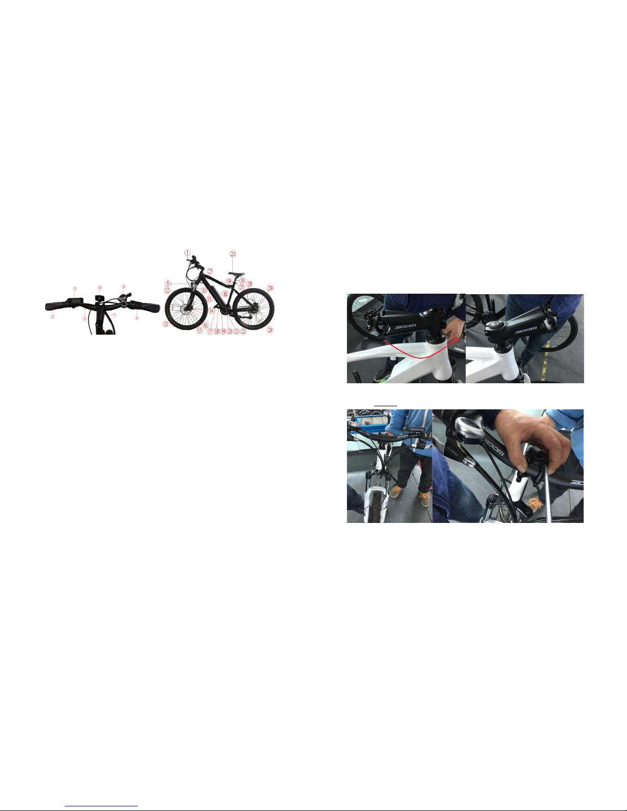
2. Spare parts
1. Brake lever 16. Disc
2. Grips 17. Pedal
3. Display 18. Crank
4. Handle bar 19. Crankset
5. Headlight 20. Middle axle
6. Throttle 21. PAS sensor
7. Stem 22. Kickstand
8. Battery 23. Saddle
9. Frame 24. Wheel reflector
10. Front fork 25. Seat post clip
11. Battery key 26. Front reflector
12. Tire 27. Controller (inside)
13. Rim 28. Chain
14.Brake clip 29. Motor
15.Spokes 30. Seat post
3
3. Assembling and adjusting
Step 1: Take the bike from the carton and take off all the protecting films and belts.
Step 2: Move the stem to the opposite side.
There are 4 screws for assembling of the handle bar.

4
Step 3: Before assembling the wheel inside the front fork. You must make sure the disc
is inside the disc clips. Otherwise you cannot put the wheel in or will break the disc
pads.
Remark: There is no hole and fork with front suspension fork.
Step 4: Generally it is unnecessary to adjust the disc brake. But if necessary, use the
screws below. The one with hand is for minor adjustment. Another one with spanner is
for big adjustment.
5
Step 5: There is only 1 screw for the fender. Screw it. It is very easy.
Step 6: On the top of the pedal shaft, “L” shows the left side pedal and “R” shows the
right pedal. Use a spanner to make the pedals tight. Please do not forget to cover the
rubber cap of the stem screw.

6
4. Checking before riding
Make sure that the brakes and the front & rear lights are all working .
Check the pressure of the tires.
Check the display works well or not.
Check the battery capacity.
This bike is not designed for rough using such as jumping, riding on rough road and etc.
.
Please note: If you use your bicycle frequently, it is recommended to inspect the
performance of the fork, the frame, the suspension and the brakes.
If you have any doubt, please contact your dealer. They will proceed with the necessary
inspection.
5. Operation and Adjustment
5.1Using the bike
◆ Start
Turn the system on with pressing the “C” (or on/off) button on the display for two
seconds. The light on the display will indicate that you have started the e-bike. Use the
throttle slightly if you have (do not use it to maximum at the beginning), you will find
that the engine starts soon.
◆Speed up
With the vehicle’s starting, you can keep on using the throttle more and more. But
please control your speed according to the situation. And also you can use the PAS to
drive the bicycle. You only need to pedal like a normal bicycle. The PAS will start
automatically. You can adjust PAS levels on the display.
◆ If you use the e-bike in the evening, make sure to turn on the front light. The
button is on the handle bar or on the top of the light itself.
7
5.2 PAS System
◆Introduction of PAS
PAS system is a pedal assisted sensor that installed in middle axis position. When you
Pedal the bicycle, the sensor will receive the action of the user. And then send the signal
to the controller. Then the controller will start the motor.
◆ How to start PAS System
Turn on the power of the bicycle and adjust PAS levels on the display. Then you only
need to pedal like a normal bicycle, The PAS will start automatically.
5.3 Safety Height Mark
◆ Handle stem position
Adjustable handle bar can be adjusted according to your favorite driving position, but it
is forbidden to be out of the safety mark.
◆Method for adjustment:
1. Screw off the adjusting screw in the stem.
2. Move the angle of the stem to your favorite but in the safety mark (safety line).
3. Screw on the adjusting screw in the stem.
◆Seat cushion position:
The height of the seat can also be adjusted according to your favorite by loosing the seat
post clip. But do not make it out of the max line (safety line).
The angle of saddle is also adjustable. You can loose the screw between the seat and
seat post to adjust.

8
5.4 Brake System
Brake system is the most important for your safety driving, so it is necessary to check
the brake system carefully before driving.
The normal idea is that the bicycle should stop in a short distance if you brake the
bicycle suddenly, but it is wrong. Suddenly
brake will not make the bicycle stop in a
short distance. The bicycle will slide
inertially. It will not only cause danger but
also increase the brake distance. So the brake system is only used for the adjustment of
the speed of bicycle.
Generally, brake system is including the brake lever, braking device (disc brake, V
brake and other brake types) and brake cable.
◆ Brake lever
The structure of the brake lever is shown in picture: the right brake lever controls the
front brake and the left brake lever controls the rear brake. But it may be different in
some countries because of the laws.
﹡Adjustable screw is used for adjusting the distance between brake pads and rim.
﹡Effective distance of the brake lever is half of the distance between the brake lever
and the grip. If the brake lever is near to the grip before braking tightly, that means there
is a very large distance between the brake pads and the rim.
◆ Disc brake (as shown in right
Pic.)
Adjustment method for brake
pads:
1.Screw off the position screw;
2.Adjust the distance of brake
pads by left/right moving.
3.Screw on the position screw.
◆ V brake (as shown in left Pic)
9
Adjustment method for brake pads:
1. Loosen the fixed screw and you will see three holes on fixed
base;
2. The elasticity will increase if you move the spring upon the
hole. This will increase the distance between brake pads and rim.
And the distance will decrease on the contrary.
◆Brake cable
﹡Bifurcation should be avoided for internal
wiring. So it is better to wear a tail sleeve at the
end of the wires.
﹡The brake cable should be pull out and oiled
regularly to avoid rusting and resistance.
﹡It is better to wire the brake cable on a line. but if it must be bent, try to avoid small
radian bending as possible.
﹡The brake cable should not be locked when the handlebar reaches the limit of left and
right turning.
5.5 Shift System
Shift system includes: Shift, front & rear derailleur, chain, flywheel and speed changing
wiring.
The speed changing levels is the number of front crankset plate ×the number of rear
flywheel plate.
For example: 3 pieces of crankset plate (front) ×7 pieces of flywheel plate (rear) =21
speed.
◆ Shift
﹡The shift includes: speed display and finger shift (as shown in the picture).
﹡Shifts are on both sides of the handle bar. The left one controls the front transmission

10
and the right one controls the rear transmission.
﹡If there the speed of the bicycle is 6,7,8 or 9. That
means there is only one plate for the crankset. So
there is only a right shift to control the speed.
◆ Rear Transmission Parts
Rear Transmission parts include front derailleur and rear derailleur. If the speed
changing wiring is too loose or too tight, you cannot change the speed smoothly. If so,
we need to make small adjusting.
When you change the speed, if the chain cannot be changed from the bigger gear to the
smaller gear. You should roll the screw to the up direction. If the chain cannot be
changed from the smaller gear to the bigger gear, you should roll the screw to the down
direction. This screw is for small adjustment. There is also a nut for a big adjustment.
You need a banner to loose or tight the wire.
5.6 Carrier
Maximum loading of the carrier should be less than 15KGS.
This luggage carrier is not designed for a trailer. Don't install the child-seat on the
carrier. The bicycle performance maybe different (particularly when steering and
braking) when the luggage carrier is loaded, please pay attention.
Please make sure that any luggage on the carrier should be safe.
Please put the luggage evenly to the two sides of the luggage carrier.
11
5.7 Battery
Installing and removing the battery
Remove the battery: turn off the lock located on the battery to the last level. Pull out the
battery slightly.
Install the battery: Put the battery on its guide. Put the battery into its socket slightly.
And lock it.
Charging the battery
Never let a battery be charged unattended.
The battery’s autonomy is indicated with the LED lights located on the battery, and also
on the display located on the handlebar.
Your battery must be charged in the regular temperature, non-flammable and dry place.
Also, it must not be covered.
On the battery, the charging place are covered by a rubber cap.
Here are the steps to be followed when charging your battery:

12
Step 1
Turn the battery off. The LED lights will be off.
Step 2
Plug the charger plug into the socket located on the charger (Pic.A).
Make sure to make them tight. And also put the battery plug into the
battery socket.
Step 3
Connect the charger to the socket in your house.
Step 4
Check the LED light on the charger:
• The red LED light is on: the battery is being charged.
• The green LED light is on: the battery is charged; you can unplug the
charger.
(A) (B)
It takes about 5-6 hours for a full charge when using the standard charger supplied by
the original bicycle company. Faster charger is not suggested to be used.
Battery autonomy and life
Autonomy
Your bicycle’s autonomy is from 45 to 70 with PAS. It depends on many different
factors (level of PAS used, different road, rider’s weight, frequent stops/start-ups, hills,
tire pressure, etc…)
Battery
With the using of the battery, the capacity of the battery will be lower and lower
gradually. If the available autonomy of the battery no longer satisfy your needs, you
13
will be able to obtain a new one from your dealer.
Maintenance
If you don’t use your bike more than 45 days, store it in a dry place to protect the
electronic components and also charge it every 45 days.
Battery safety instructions
For your safety, you should follow these rules:
Note: Never store a completely discharged battery .
During the winter or long storage periods, it is recommended to charge the
battery every 45 to 60 days. Don’t forget to switch it off. Store your battery at a
temperature between 15° to 25°.
Always handle with great care
Always keep it away from children
Do not open, hit, pierce or submerge it
Keep it away from more than 60° temperatures.
Never create a connection between the +/- plugs.
Never let the battery charge unattended
Never sleep near a battery when it is charging
Only use the charger come with your bicycle or supplied by your dealer
If your battery is damaged, do not use it and take it back to your dealer as soon
as possible

14
5.8 Lubrication
Frequency
Component
Lubricant
How to Lubricate
Weekly
Chain
Speed shift
Pulleys
Derailleurs
Brake Calipers
Brake Levers
Chain Lube
Oil
Chain Lube
Oil
Oil
Oil
Brush On or Squirt
Brush On or Squirt
Oil Can
3 drops from oil can
2 drops from oil can
Monthly
Shift Levers
Lithium Based Grease
Disassemble
Every Six Months
Freewheel
Brake Cables
Oil
Grease
2 squirts from oil
can
Disassemble
Yearly
Bottom Bracket
Pedals
Derailleur
Cables
Wheel Bearings
Headset
Seat Post
Grease
Grease
Grease
Grease
Grease
Grease
Disassemble
Disassemble
Disassemble
Disassemble
Disassemble
Disassemble
Note: The frequency of maintenance should increase with using in wet or dusty
conditions. Do not over lubricate. Never use a degreaser to lubricate your chain
5.9 LCD display operation
. Shape, Size and Material
The shell of this product is ABS,The transparent LCD window is imported high
hardness Acrylic. It is as harder as the toughened glass.
15
Front view Side view
.Working voltage and wiring
1、working voltage:DC24V /36V compatible、36/48V compatible(set on LCD),
Other voltage can be customized.
2、Wiring:
Standard connector wiring
Bracket side view
16
Connector to the controller LCD outlet terminal abutment terminal
Standard connector wiring turns
wiring turns
color
function
1
Red(VCC)
Power wire
2
Blue(K)
Controller and power controlling
wire
3
Black(GND)
Earth wire
4
Green(RX)
Data receiving wire
5
Yellow(TX)
Data sending wire
EXTENTION FUNCTION:
Headlight:Brown(DD): headlight positive pole,
White(GND): headlight negative pole。
P WM Voltage type assistance controlling out independence speed sensor,
Order new function for different color of wire。
Marks:Some products are using water-proof connector,User cannot see the
color inside.
.Functions:
1、Display function
Speed display、Assistance display、Battery power display、Fault display、Total range
display、current range display、fix-speed cruise、brake display、headlight display
2.Control and set function
17
Power control 、headlight control 、6Km/h control 、fix-speed cruise control、rim size
set、5 levels assistance set、max speed set、Automatic dormancy set、back light
brightness set、Starting method set、driving method set、assistance sensibility set、
assistance magnet disc type set、voltage set、current-limit of controller set,
3.communication protocol:UART
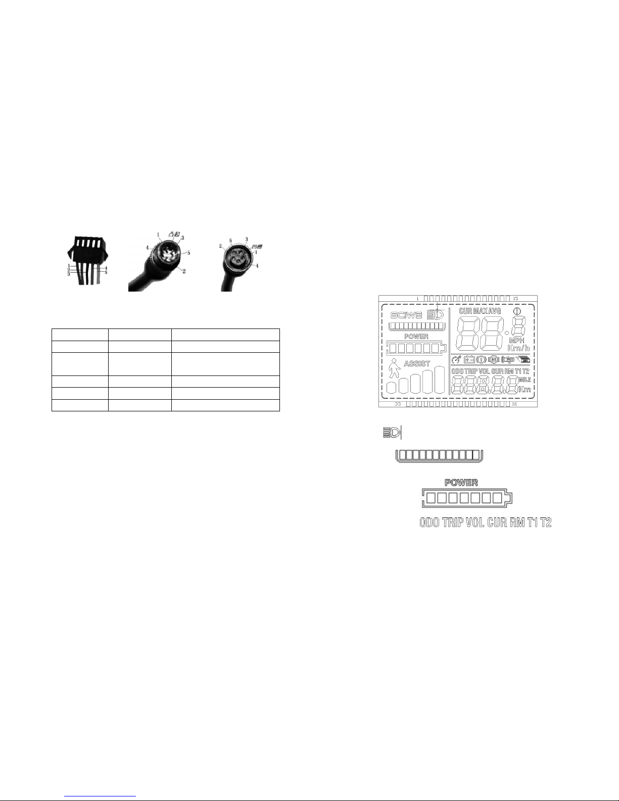
ALL ON DISPLAY(power on within 1S)
Display introduction
1 Headlight
2. Current levels This function needs a software
support in controller.
3. Voltage levels POWER
4.Multifuction display area
Total range ODO、Current range TRIP、Voltage VOLT、Current CURRENT、Rest of
range RM(a software support in BMS needed)、 working time TIME

18
5. Speed display area
Current speed CUR、Max speed MAX、Average speed AVG
Unit MPH, KM/H
The display will calculate the speed according to the rim size and signal data (Motor
hall need to set the magnet quantity ).
6. Fault display area
Motor fault 、Throttle fault 、controller fault 、brake lever
fault 、protecting of under voltage
7.Assistance display area
Assistance (0-5 levels)、Cruise
8.Setting
P01:Brightness of the backlight ,1 is the lowest level,3 is the highest level;
P02:Unit of the range,0:KM;1:MILE;
P03:Voltage:24V,36V,48V,Default 36V;
P04:Dormancy time:0,no dormancy;Other numbers is the dormancy time,
unit is 0-60 minutes;
19
P05:Assistance level : 0-3levels:1 level 2V,2 level,3V,3 level,4V;
1-5levels: 1 level 2V,2 level,2.5V,3 level,3V,
4 level,3.5V,5 level,4V;
P06: Rim size:Unit,inch;precision:0.1;
P07: Number of magnet steel:Range:1-100;
P08: Speed limit:Range 0-50km/h,50 means no speed limit,
1. No signal communication condition(Display controlling):When
the actual speed larger than setting speed,Turn off the PWM
output;When the actual speed less than the setting speed,Turn on
the PWM output automatically,Driving speed is the current
speed ±1km/h;( Only limited to PAS not Throttle)
2. Signal communication condition(Controller controlling):Driving
speed will be kept to the setting speed.
Tolerance:±1km/h;( Limited to both PAS and throttle)
Mark: The data here is based on KM. When the unit setting is Mile, The
speed on the display is correct Mile. But the data setting in this menu
will not be changed. So it is different to the actual speed.
P09:Zero starting、Unzero starting setting,0:Zero starting;1:Unzero starting;
P10:Driving method setting
0 : Assistance driving(Throttle is unusable)。
1 : Throttle driving(PAS is unusable)。
2 : Both Assistance and throttle driving(The Zero
starting is unusable when under throttle
driving)。
P11:Sensitivity of PAS Range:1-24;
P12:Strength of PAS starting Range:0-5;
P13:Magnet types of PAS setting 5,8,12 three types
P14:Current limit of controller Default 12A Range:1-20A
P15:This function has not developed

20
P16: ODO set to 0. Long press the top button for 5s.
. Button introduction:
Buttons will be like this
Button using introduction
Button operations are short press, long press and combination long press.
Short press is used for convenient and frequent operations. For example:
1. When riding,If you need to change the assistance or
speed,short press.
2. Change to multifuction area when riding, short press.
Single button long press is used for mode and switch.
Combination press(long press) is used for parameter setting.
Operation details:
1. Modify assistance levels
21
1.Short press ,Assistance + 1
2.Short press ,Assistance - 1
2.Change to speed display
Long press +
3.set/clear 6KM/H cruise, headlight turn on/off
Stop vehicle,long press ,will be 6KM/h cruise;Long press when
riding,it will be fix speed cruise,If it is under fix speed cruise currently,it will release
cruise;
Long press turn on/off headlight.
4.Turn on/off display
Long press

22
5.Change to multifuction display area
Short press
6.Setting parameter
Long press +will be into parameter setting page,the
parameter setting can be including,
Rim size(inch),number of magnet steel,brightness of the display, under voltage
point and etc.(setting:P01-P14);
In the page of parameter setting,short press +parameter,or short press
-parameter,parameter will be shining after setting,after choose the
parameter,
4.a.Long press to save, shining will be stop.
b.short press to change to next parameter and save the last parameter
23
at the same time.
2. Press +,quit setting and save,If you do not press,it will
quit and save automatic after 10S.
Marks:Because of the updating of the products, there may be some difference
between the product you get and the manual. But it will not affect your using.
6. Recommended safety instructions and maintenance
6.1 Recommended safety instructions
Helmet
Use a bicycle helmet.
Tires
Inspect the abrasion of your tires on a regular period and check the tire pressure at least
once a month.
Reflector
Please make sure that the position of reflectors and lamps are not obscured when
luggage is attached to the luggage carrier
Battery
Cf. Chapter. 4.7
6.2 Maintenance
Caution:
Bike maintenance and repairing needs more skills and professional tools. Do not repair
your bike or change any settings by yourself. Contact your dealer to do that. Any bad
adjustment or repairing can damage the bike and lead to accidents. Using the replacing
parts from your dealer only.
Cleaning
Always remove the battery when cleaning. Use soapy water or water mixed with a
gentle detergent, and then rinse with clean water.
Make sure to keep the controller dry.
Do not use a high-pressure washer!

24
Maintenance
Your electric bicycle is safe for the environment.
A battery that no longer works must be returned to your dealer so that he may pass it to
a recycling company.
The engine does not require maintenance.
7. Regular maintenance
7.1 Recommended values of the nut torque
Front Wheel Nuts
22-27 Newton Meters
16.2-19.8 ft.-lb.
Rear Wheel Nuts
24-29 Newton Meters
17.5-21.3 ft.-lb.
Seat Binder Nut
12-17 Newton Meters
8.8-12.5 ft.-lb.
Seat Pillar Clamp Nut
15-19 Newton Meters
11.0-14.0 ft.-lb.
Brake Anchor Nut
7-11 Newton Meters
5.1-8.1 ft.-lb.
Handlebar Clamp Nut
17-19 Newton Meters
12.5-14.0 ft.-lb.
Head Stem Expander
Nut
17-19 Newton Meters
12.5-14.0 ft.-lb.
Crank Cotter Pin Nuts
9-14 Newton Meters
6.6-10.3 ft.-lb.
Brake Centre Bolt
2-17 Newton Meters
1.5-12.5 ft.-lb.
7.2 Recommended Checklist
Frequency
Task
Before every ride
Be sure batteries are fully charged
Check tire pressure
Check brake operation
Check spokes loosing
After every ride
Be sure to fully charge batteries
Wipe the water quickly
Weekly
Lubrication as per schedule4.8
Inspect wires
25
Monthly
Inspect connectors
Check derailleur adjustment
Check brake adjustment
Check brake and gear cable adjustment
Check tire abrasion and pressure
Check wheels and spokes tightness
Check hub, head set, crank and bearings looseness
Check pedals tightness
Check handlebars and stem tightness
Check seat and seat post tightness and comfortably adjusted
Check frame and fork for safty
Lubrication as per schedule4.8
Safety check
Every six months
Lubrication as per schedule 4.8
Check all points as per monthly service
Check and replace brake pads if required
Check chain abrasion
Yearly
Lubrication as per schedule 4.8
8. Fault and Solving
NO.
Fault
Reason
Solving
1
Speed adjustment
is not sensitive or
the max speed is
too low
1.Low battery voltage
2.Something is wrong
with the throttle
3.Something is wrong
with controller
1.Recharge the storage battery
2.Replace the throttle and
controller

26
9. Warranty
Information regarding your electric bicycle warranty coverage terms is available from
your dealer. When you need a replacement or repairing under your warranty, you should
send the numbers of frame, motor, battery and controller. And also provide pictures or
videos to prove the damage and not caused by human.
Have a pleasant riding!
2
The motor does
not work when the
power is on
1.Something is wrong
with the throttle
2.Bad connecting of the
power lock and plugs
3.Something is wrong
with controller
4.Something is wrong
with PAS sensor
1.Replace the throttle,
controller or PAS sensor
2.Weld the connecting part
again
3.Adjust the distance between
the two parts of the PAS
sensor.
3
Less mileage for
once charge
3.Tire pressure is less
4.Wrong charge or the
fault of charger
5.Storage battery is
damaged or end of life
6.Frequent braking
starting and overloading
1.Make the tire with more
pressure
2.Right charge the storage
battery or replace charger
3.Replace the storage battery
4
The charger fails
to charge
1.The connection of the
charger is loose or
damaged
2.The welding points of
the storage battery falls
off or damaged
1.Weld connections or replace
it
2.Weld connections or replace
it
5
The PAS fails to
assist power
1.Bad contact of the
sensor or it is damaged
2.Bad contact of PAS or
it is damaged
1.Adjust the place of the
sensor or replace it
2.Connect the lines
Table of contents


