champion spas 108 User manual

OWNERS MANUAL
champion spas®
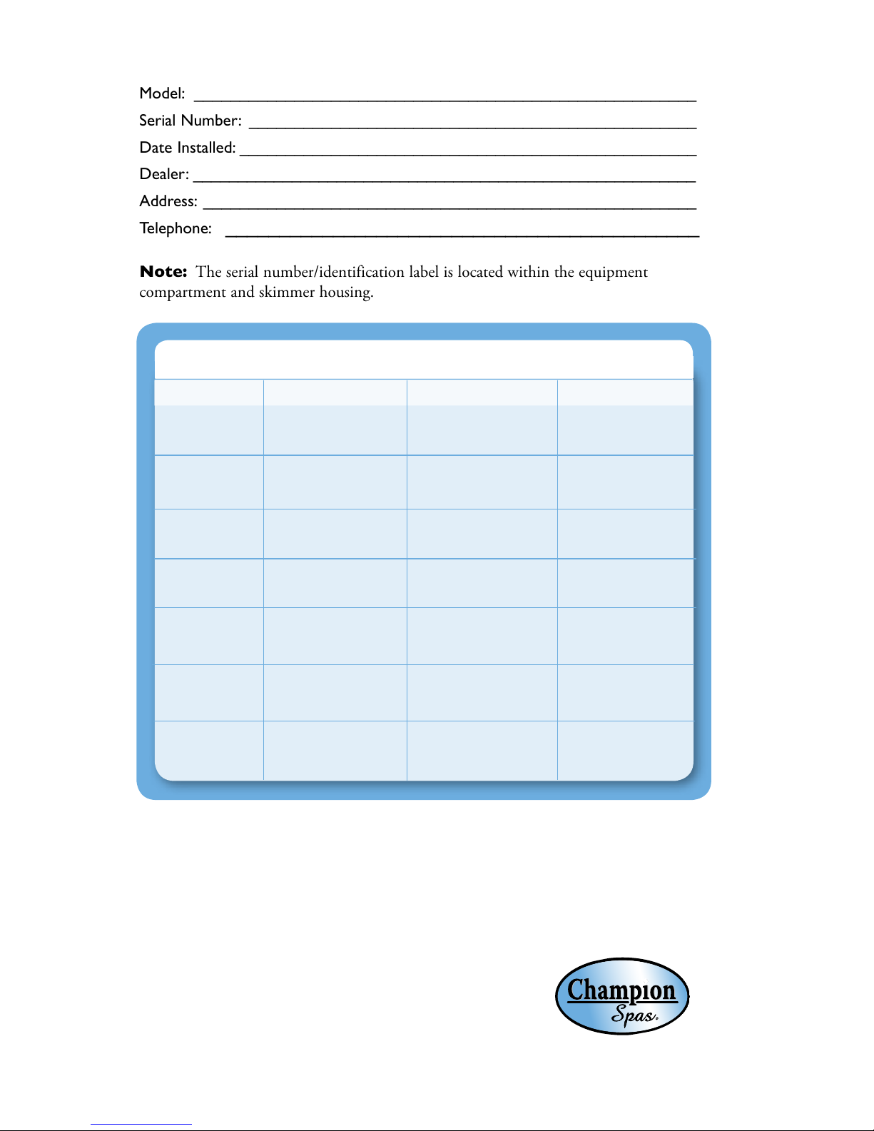
Model: _______________________________________________________
Serial Number: _________________________________________________
Date Installed: __________________________________________________
Dealer: ________________________________________________________
Address: ______________________________________________________
Telephone: ____________________________________________
Note: The serial number/identification label is located within the equipment
compartment and skimmer housing.
CHAMPION SPAS®
MODEL AVG. FILL AVG. FILL WEIGHT AVG. DRY WEIGHT
240 gal. / 909 L
150 gal. / 568 L
150 gal. / 568 L
240 gal. / 909 L
350 gal./ 1325 L
350 gal. / 1325 L
450 gal. / 1703 L
2278 lbs. / 1033 kg.
1500 lbs. / 680 kg.
1650 lbs. / 748 kg.
2600 lbs./ 1179 kg.
3500 lbs./ 1587 kg.
3500 lbs. / 1587 kg.
4400 lbs. / 1996 kg.
310 lbs. / 141 kg.
300 lbs. / 136 kg.
385 lbs. / 175 kg.
480 lbs. / 217 kg.
700 lbs/ 318 kg.
700 lbs. / 318 kg.
725 lbs./ 329 kg.
Thank you for your recent Champion Spas® purchase.
This owner's manual has been designed to acquaint you with your Champion Spas®
operation and general maintenance. Keep this manual available for future reference.
If you have any questions regarding your Champion Spas® model, contact your local dealer.
Thank you.
108
213
320
650
540
436
215

CHAMPION SAFETY INSTRUCTIONS
Avoiding Risk to Children .................. 2
Avoiding Risk of Electrical Shock ............. 2
Avoiding Risk of Injury..................... 3
Unclean Water ........................... 3
Avoiding Risk of Hyperthermia............... 4
Avoiding Risk of Skin Burns ................. 4
Important Do's and Don'ts.................. 5
CHAMPION SPAS® MODELS
Specifications ............................ 6
INSTALLATION INSTRUCTIONS
Location Preparation....................... 7
Outdoor Installation ...................... 7
Indoor Installation ........................ 7
ELECTRICAL REQUIREMENTS
AND PRECAUTIONS
220 V Permanently Connected Models ........ 8
Electrical Installation Instructions ...........8-9
Electrical Spa Wiring Connection Instructions ... 9
110/220 Volt Convertible Models .........10-11
INITIAL OPERATING INSTRUCTIONS
Start-up and Refill Procedures .............. 12
Model Start-up Procedures ................. 13
EQUIPMENT MAINTENANCE
Light Bulb Replacement ................... 14
CONTROL PANEL FUNCTIONS
Main Control Panel ...................... 14
Main Control Panel Navigation ............. 14
Temperature Controls ...................14-15
Panel Functions.......................... 15
Hold, Lock/Unlock, 24 Hour Clock,
Temp Display, Flip Button
Operating the Hydro Pumps................ 16
Jet Buttons ......................... 16
Clean-up cycle....................... 16
Light Control Button ................. 16
Optional LED Lighting Systems......... 16
Heating Modes .......................... 17
Filter Cycle Modes ....................... 18
Reminder Messages ....................... 19
Diagnostic Messages ...................... 20
SPA CARE & WATER MAINTENANCE
General Information ..................... 21
Filter Cartridge Removal and Cleaning ....... 22
Care of Pillows ........................22-23
Care of Exterior ......................... 23
Care of Spa Cover .....................23-24
Winterizing Your Spa ...................24-25
Water Quality Maintenance ..............26-28
TROUBLESHOOTING
Operational Trouble Shooting Guide .......29-30
Control Panel Identification ................ 30
SERVICE & WARRANTY INFORMATION
Service and Warranty Information ........... 31
Spa Care and Maintenance Record .......... 32
TABLE OF CONTENTS

2Champion Spas®
OWNER'S MANUAL
CHAMPION SPAS® SAFETY INSTRUCTIONS
Read And Follow All Instructions
AVOIDING THE RISK TO CHILDREN
RISK OF CHILD DROWNING
Extreme caution must be exercised to prevent unauthorized access by children. To avoid
accidents, ensure that children cannot use a spa unless they are supervised at all times.
• Toreducetheriskofinjury,donotpermitchildrentousethisspaunlesstheyareclosely
supervisedatalltimes.
•Toreducetheriskofinjury,lowerwatertemperaturesandcontrolthetimeofhotwater
exposureforyoungchildren.Childrenareespeciallysensitivetohotwater.
RISK OF ELECTROCUTION
• Connect only to a grounded source.
• Do not bury the power cord. A buried power cord may result in death, or serious
personal injury due to electrocution if direct burial-type cable is not used, or if
improper digging occurs.
• A ground terminal (pressure wire connector) is provided on the control box inside the
unit to permit connection of a minimum No. 8 AWG (8.4 mm) solid copper bonding
conductor between this point and any metal equipment, metal water pipe, metal
enclosures of electrical equipment, or conduit within five feet (1.5 m) of the unit as
needed to comply with local requirements.
• To reduce the risk of electrocution, replace all damaged cords immediately. Failure to
do so may result in death or serious personal injury due to electrocution.
• Do not connect any auxiliary components (for example, additional cable speakers,
headphones or other audio components) to the audio system unless approved by
Saratoga Spa® Company.
• Do not self-service audio components by opening or removing the cover as this
may expose you to dangerous voltage or other risk of injury. Only qualified service
personal should service your spa and it's components.
• Do not attach an external antenna to a spa audio system unless it is installed by a
licensed electrician in accordance with Article 810 of the National Electric Code,
ANSI/NFPA 70.
AVOIDING RISK OF ELECTRICAL SHOCK
• Do not permit any electrical appliance, such as a light, telephone, radio or television
within 5 feet (1.5m) of a spa. These units DO NOT have an internal ground fault
circuit interrupter. The installation of a ground fault circuit interrupter MUST be
done by a qualified Electrician and must meet all local and national codes. Failure
to maintain a safe distance may result in death, or serious personal injury due to
electrocution, if the appliance should fall into the spa.
!
!
!
!
!
!

3
Champion Spas®
OWNER'S MANUAL
• Install at least 5 feet (1.5 m) from all metal surfaces. A spa may be installed within 5 feet
of a metal surface if each metal surface is permanently connected by a minimum No. 8
AWG (8.4 mm) solid copper conductor attached to the wire ground connector on the
terminal box that is provided for this purpose if in accordance with National Electrical
Code ANSI/NMFPA70-1993.
• Install your spa in such a way that drainage is away from the electrical compartment
and from all electrical components.
AVOIDING RISK OF INJURY
• To reduce the risk of injury to persons, DO NOT remove suction fittings located at
the bottom footwell of the spa.
• The suction fittings in the spa are sized to match the specific water flow created by the
pump. Never replace a suction fitting with one rated less than the flow rate marked on
the original suction fitting. Never operate the spa if the suction fittings are broken or
missing.
• There is a danger of slipping and falling. Remember that wet surfaces can be very
slippery. Take care when entering or exiting the spa.
• People with infectious diseases should not use the spa.
• Keep any loose articles of clothing or hanging jewelry away from rotating jets or other
moving components.
• The use of drugs, alcohol, or medication before or during spa use may lead to
unconsciousness with the possibility of drowning.
• Persons using medications should consult a physician before using a spa; some medication
may cause a user to become drowsy, while other medication may affect heart rate, blood
pressure, and circulation.
• Persons taking medications which induce drowsiness, such as tranquilizers,
antihistamines or anticoagulants should not use the spa.
• Water temperature in excess of 104ºF (38ºC) may be injurious to your health.
• Pregnant women should consult a physician before using spa.
• Persons suffering from obesity, or with a medical history of heart disease, low or high
blood pressure, circulatory system problems, or diabetes should consult a physician
before using spa.
• Persons using or having Implanted Pacemakers or Defibrillators should consult their
physician prior to using a spa, as there are risks of electrocution.
UNCLEAN WATER
• Keep the water clean and sanitized with correct chemical care.
• Maintain water chemistry in accordance with chemical manufacturer’s instructions.
Important:
• Turn the Jet Pump on high speed and it will operate for a 15 minute cycle after adding ANY
spa water chemicals into the spa.
• Clean the filter cartridges monthly to remove debris and mineral buildup which may
affect the performance of the jets, limit the flow, or cause a high limit problem.
!
!

4Champion Spas®
OWNER'S MANUAL
AVOIDING RISK OF HYPERTHERMIA
The causes, symptoms and effects of hyperthermia may be described as follows:
Hyperthermia occurs when the internal temperature of the body reaches a level several
degrees above the normal body temperature of 98.6ºF. The symptoms of hyperthermia
include an increase in the internal temperature of the body, dizziness, lethargy,
drowsiness and fainting.
The effects of hyperthermia include:
1. Failure to perceive heat.
2. Failure to recognize the need to exit the spa or hot tub.
3. Unawareness of impending hazard.
4. Fetal damage in pregnant women.
5. Physical inability to exit the spa or hot tub.
6. Unconsciousness resulting in drowning.
Theuseofalcohol,drugs,ormedicationcangreatlyincreasetheriskoffatal
hyperthermiainhottubsandspas.
To Reduce The Risk of Injury:
• The water in the spa should never exceed 104°F (40ºC). Water temperatures between
100°F (37.7ºC) and 104°F (40ºC) are considered safe for a healthy adult.
• Lower water temperatures are recommended for extended use (exceeding ten
minutes) and for young children. Extended use can cause hyperthermia.
• Pregnant or possibly pregnant women should consult with their physician before
entering a spa. Failure to do so may result in permanent injury to your baby.
• Do not use spa immediately following strenuous exercise.
AVOIDING RISK OF SKIN BURNS
• To reduce the risk of injury, before entering a spa the user should measure the water
temperature with an accurate thermometer, since the tolerance of temperature-
regulating devices may vary by as much as ±5°F.
• Test the water with your hand before entering the spa to be sure it’s comfortable.
!
!
!
!
!
!
!
!

5
Champion Spas®
OWNER'S MANUAL
Do:
• Make sure you always lock the child resistant spa cover locks after using the spa for
your children’s safety. Every Champion Spas® model is equipped with a locking cover
that meets the ASTM F1346-91 Standard for Safety Covers.
• Test the water temperature with your hand before allowing children to enter the spa to
be sure that it’s comfortable. Children are especially sensitive to hot water.
• Remind children that wet surfaces can be very slippery. Make sure that children are
careful when entering or exiting the spa.
• Use and lock the vinyl cover when the spa is not in use, whether it is empty or full.
• Follow the Spa Care and Maintenance recommendations stated in this manual.
• Use only approved accessories and recommended spa chemicals and cleaners.
• Keep the spa cover locked when the spa is not in use.
• Check the equipment compartment monthly for any signs of tampering to the spa
equipment.
• Follow the maintenance instructions of the spa found in this owner’s manual.
• Be sure your spa is connected to the power supply correctly - use a licensed electrical
contractor.
• Test the Ground Fault Circuit Interrupter(s) once a month.
• Place the spa on a level load bearing surface.
Don't:
• Allow children or pets to climb onto the spa cover.
• Allow children to have unsupervised access to the spa.
• Leave the Champion Spas® exposed to the sun without water or the cover in place.
Exposure to direct sunlight can cause solar distress of the shell material and will void
the warranty.
• Lift or drag the vinyl cover by using the cover lock straps; always lift or carry the cover
by using the handles.
• Attempt to open the electrical control box. There are no user serviceable parts inside.
Opening of the control box by the spa owner will void the warranty. If you have an
operational problem, carefully go through the steps outlined in the Troubleshooting
section. If you are not able to resolve the problem, contact your authorized Champion
Spas® dealer. Many problems can easily be diagnosed over the telephone by an
Authorized Service Technician.
• Block or sit on the filter compartment area.
• Allow excessive weight to be placed on the spa cover. Doing so could damage the spa
cover and void any warranty.
• Use the spa with the equipment compartment door removed.
• Place electrical appliances within 5 feet (1.5m) of the spa.
• Block the equipment compartment vents. This could cause damage to the spa
equipment and will void the warranty.
* SAVE THESE INSTRUCTIONS *
IMPORTANT DO'S & DON'TS
Important:
The following contains important spa information, and we strongly encourage you to read
and apply them.
!
!
!
!

6Champion Spas®
OWNER'S MANUAL
Width Length Height Average Dry Average Seating
Fill Weight Fill Weight Locations
108 78.5” Round 31.5” 240 gal 310 lbs. 2,278lbs. 3
2 m Round 0.80 m 909 L 141 kg 1033 kg
213 59” 82” 29” 150 gal 300 lbs. 1,500 lbs. 2
1.49 m 2.08 m 0.74 m 568 L 136 kg 680 kg
215 57" 80" 29" 150 gal 385 lbs. 1650 lbs 2
1.45 m 2.03 m 0.74 m 568 L 175 kg 748 kg
320 67” 80” 32” 240 gal 480 lbs. 2600 lbs. 3 - 4
1.70 m 2.03 m 0.80 m 909 L 217 kg 1,179 kg
436 80" 84" 36" 350 gal 700 lbs. 3,500 lbs. 5
2.03 m 2.13 m 0.91 m 1,325 L 318 kg 1,587 kg
540 80” 84” 36” 350 gal 700 lbs. 3,500 lbs. 5
2.03 m 2.13 m .91 m 1,325 L 318 kg 1,588 kg
650 89" 93" 40 " 450 gal. 725 lbs. 4,400 lbs. 6
2.26 m 2.36 m 1.02 m 1,703 L 329 kg 1,996 kg
Due to the risk of property damage and injury, the manufacturer of the Champion
Spas® strongly suggests a structural engineer or contractor be consulted before the spa
is placed on an elevated deck.
Note: The “Average Full” weight of the spa includes only the spa and the water inside the spa.
SPA SPECIFICATIONS
!
!

7
Champion Spas®
OWNER'S MANUAL
INSTALLATION INSTRUCTIONS
Location Preparation
Your Champion Spas®model is totally self-contained and portable. You can install the spa
outside or inside. Preferable places are on a patio, deck or indoors. The spa should always be
placed on a level, load bearing surface in accordance with your local building code requirements.
Other items you need to consider are the following:
• Verify that the location chosen can support the weight of the spa, the water of the spa and
its occupants.
• Always check the surface of the site to see if it is level before filling the spa with water.
• Allow access to the equipment compartment for routine maintenance.
• When positioning the spa, be sure to allow for drainage away from the electrical compartment.
• Leave easy access to the GFCI breaker.
ChampionSpas®ismanufacturedtobeaportableunit.Anypermanentinstallation
ofthisproductisdoneattheriskoftheowner.Permanent
installationofthisunitviolateswarrantycoverage.
Outdoor Installation
Always keep in mind what type of climate you live in. In a climate with cold, snowy winters you
may want to consider locating the spa close to the house for easy access. In climates where it is
normally warm or hot year-round, it would be recommended to place the spa in a shaded or cool
area. With deck installations it is recommended that a qualified building contractor or structural
engineer review the weight the deck can support. The spa specification sheet (on page 6) can
assist you with the weights and dimensions of your spa.
Indoor Installation
Special requirements are needed for indoor installation. Spas normally produce moisture. A
ventilation system needs to be considered. Your spa area should contain moisture resistant wall/
floor coverings and building materials to avoid damage from moisture over time. Proper drainage
of the spa water also needs to be considered.
Your Champion Spas® model is equipped with air vents to allow for circulation of
air throughout the equipment compartment. These vents are found on the face of the
equipment compartment panel and under the corners of the spa at the equipment
compartment end. Do not allow vents to be blocked as to prevent the circulation of
air in the equipment compartment.
Your Champion Spas® dealer can help you with information such as local
zoning regulations and building codes.
!
!
!
!

8Champion Spas®
OWNER'S MANUAL
ELECTRICAL REQUIREMENTS AND PRECAUTIONS
Your Champion Spas® model has gone through numerous tests to verify that all of the spa
functions operate. Beyond the tests, your Champion Spas® model has been designed to
provide the maximum safety against electrical shock. Read and follow the electrical installation
requirements and instructions completely. The next few pages will assist you in properly
connecting the electrical input. Follow the electrical instructions for your specific spa model.
Serious risks or injuries may occur if the spa is improperly wired.
220 Volt Permanently Connected Models:
• 108* • 213* • 215* • 320* • 436 •540 • 650
*This model is convertible to 110V—See page 10 for installation instructions.
Champion Spas® must be wired in accordance with all applicable local electrical codes.
Use NEC 250-122(table) and local codes for more information. All electrical work
should be done by an experienced, licensed Electrician. We recommend the use of
appropriate electrical conduit, fittings and wire for all circuits.
220 Volt installations require a 60Hz, single phase, three-wire electrical service plus
ground (Line 1, Line 2, Neutral and Ground) and must be connected using a minimum
supply conductor ampacity of 50 AMPs and a minimum circuit breaker size of 50 AMPs.
Note: Use copper wire only (3 wire with ground; 8 gauge under 50', 6 gauge over 50')
220 Volt model spas must be connected to a “dedicated” 220 volt 50 Amp grounded
circuit. The term “dedicated” means the electrical circuit is not being used for any other
electrical items (lights, appliances, etc.). If the spa is connected to a non-dedicated
circuit, overloading will occur and nuisance tripping of the GFCI breaker switch at the
house breaker panel will occur.
A ground lug connector is provided on the exterior surface of the spa pack (operations
center) inside the equipment compartment. This is to permit the connection of a
bonding wire between this point and any metal equipment, enclosures, pipe or conduit
within five feet (1.5m) of the spa. This bonding wire must be at least 8AWG solid
copper wire.
Due to the risk of equipment damage or fire, use only approved pressure-type wire
splicing lugs or connectors suitable for the size and type of wiring used.
Electrical Installation Instructions for 220 Volt Models
1. To connect the electrical service, first remove the screws from the equipment compartment
door. Carefully remove the access panel.
2. Locate the spa power pack. Loosen the screws on the front of the control box. Remove the
screws and the control box cover.
3. Input the electrical service from the GFCI breaker into the spa equipment compartment.
The GFCI breaker must be placed in sight of the spa, at a minimum distance of five
feet (1.5m) away.
As of January 1, 1996 the National Electric Code (NEC) requires GFCI (Ground Fault
Circuit Interrupter) on all spa installations.
4. Connect the supply conduit to the spa power pack.
!
!
!
!
!
!
9
Champion Spas®
OWNER'S MANUAL
Electrical Spa Wiring Connection Instructions
Due to the risk of damaging the PC Board, the equipment and the GFCI tripping,
never, under any circumstances, should you connect power to the neutral terminal.
1. Identify the TB1 terminal block, located inside the spa power pack on the left side.
2. Connect the 8 AWG, WHITE wire, from the GFCI 50 amp breaker,to the WHITE "NEU"
terminal on TB1.
3. Connect the 8 AWG, BLACK wire, from the GFCI 50 amp breaker, to the BLACK "HOT"
terminal on TB1.
4. Connect the 8 AWG, RED wire, from the GFCI 50 amp breaker, to the RED "HOT"
terminal on TB1.
5. Connect the 8 AWG, GREEN wire, from the GFCI 50 amp breaker, to the GREEN
"GROUND" location on the "BONDING LUGS" terminal.
6. At least two additional lugs marked “BONDING LUGS” are provided on the external surface
of one of the bonded components metal enclosures. To reduce the risk of electrical shock,
connect the local common bonding grid in the area of the hot tub or spa to these terminals
with an insulated or bare copper conductor not smaller than No. 6 AWG.
7. All field-installed metal components such as rail, ladders, drains or other similar hardware
within 10 ft (3m) of the spa or hot tub shall be bonded to the equipment grounding bus with
copper conductors not smaller than No. 6 AWG.
8. Replace the control box cover and securely tighten the fastening screws. Close and secure the
equipment compartment panel.
Always use copper wire only (3 wire with ground; 8 gauge under 50ft, 6 gauge over
50ft). The electrical supply for this product must include a suitable rated switch or
circuit breaker to open all ungrounded supply conductors to comply with Section
422.20 of the National Electrical Code ANSI/NEPA 70-1987. The disconnecting
means must be readily accessible to the tub occupant but installed at least 5 feet (1.5m)
from tub water
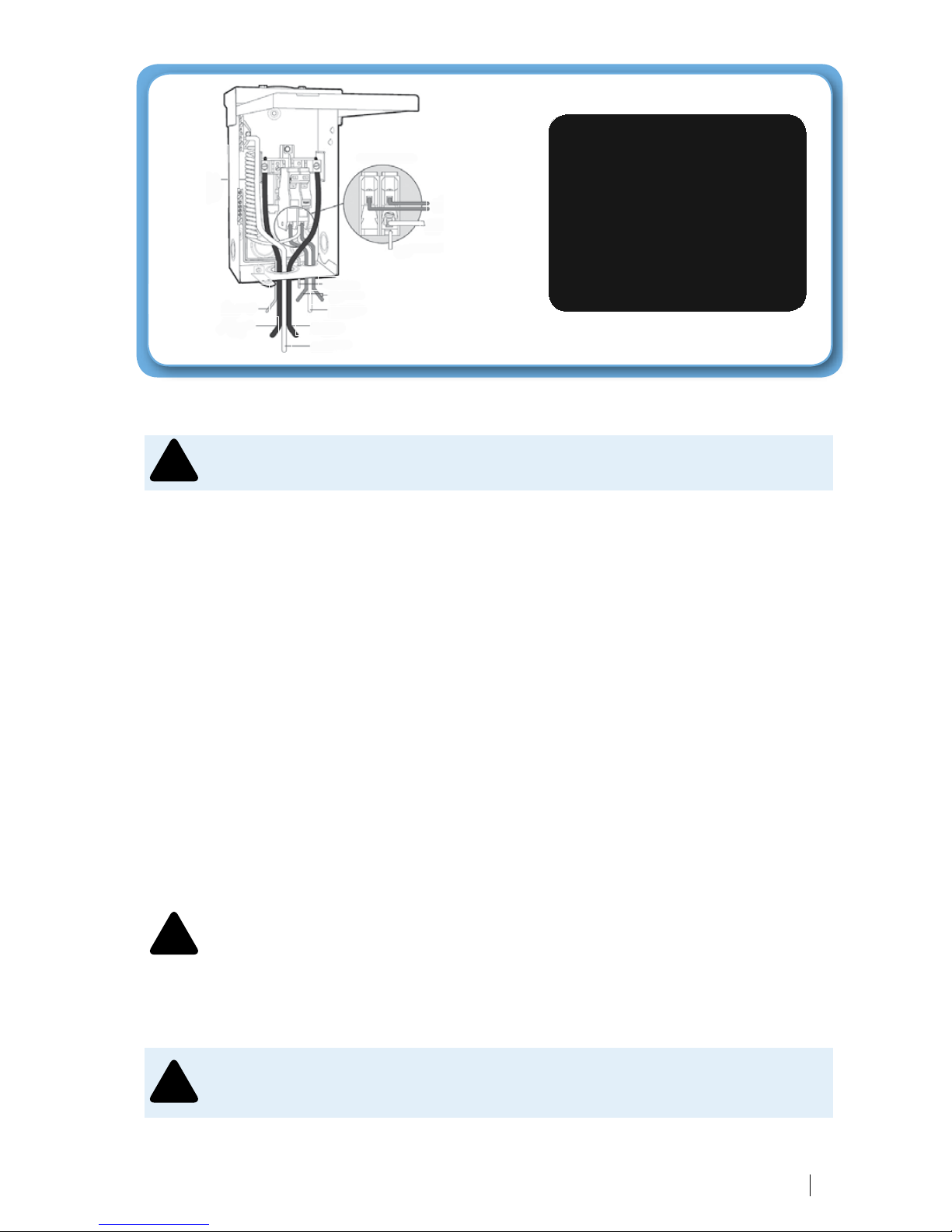
Please review the back of the spa pack cover, located in the spa equipment bay, for a
complete spa equipment wiring diagram.
PowertoSpa
NeutraltoSpa
Factory
Installed
Neutral
(Pigtail)
GroundtoSpa
OutgoingPowertoSpa
OutgoingNeutraltoSpa
IncomingPower(BlackorRed)
IncomingNeutral(White)
Incoming
Power(Black)
Incoming
Ground(Green)
BOTTOM VIEW
OF BREAKER
!
!
!
!
!
!

10 Champion Spas®
OWNER'S MANUAL
110 / 220 VOLT CONVERTIBLE MODELS
• 108* • 213* • 215* • 320*
110 VOLT ELECTRICAL REQUIREMENTS:
*The above models are manufactured with the Champion Spas® 110V/220V convertible spa
pack. The unit is factory wired for 220 Volt applications with 4 kW heater operation. The model
can be converted for 110 Volt applications and to run with a 1 kW heater operation.
The 110 Volt model must be connected to a “dedicated” 110 Volt 20 Amp grounded
circuit. The term “dedicated” means the electrical circuit is not being used for any other
electrical items (lights, appliances, etc.). If the spa is connected to a non-dedicated
circuit, overloading will occur and nuisance tripping of the GFCI breaker switch at the
house breaker panel or GFCI cord will occur. Never connect the spa to an extension
cord due to the potential for fire from wires overheating.
The 110 Volt models may be optionally equipped with a GFCI power cord
(approximately 13 feet long). This model must be plugged into a grounding type,
110 Volt 20 Amp receptacle as shown below. No other electrical appliances or fixtures
should be used on this circuit.
Theuseofanyotherreceptacleortheconnectionoftheplugtoa220Voltservicemay
causethespapacktooperateimproperly,createthepotentialforanelectricalhazard
andmayvoidthespawarranty.
Champion Spas® models must be wired in accordance with all local electrical codes. All
electrical work should be done by an experienced, licensed electrician familiar with spa
installations.
Note: As of January 1, 1996 the National Electrical Code (NEC) requires a GFCI
(Ground Fault Circuit Interrupter) on all spa installations.
CORRECT INCORRECT
Data label amperage rating of 16 Amps must use
this type of 20 Amp dedicated receptacle and plug.
Dedicated110V,20AReceptacle Dedicated110V,15AReceptacle
Do not use this type.
!
!
!
!

11
Champion Spas®
OWNER'S MANUAL
INSTALLATION INSTRUCTIONS:
The following instructions are for the conversion of the Champion Spas® models 110V/220V
control pack from a 220 Volt application to a 110 Volt application.
Due to the risk of equipment damage or fire, use only approved pressure-type wire
splicing lugs or connectors suitable for the size and type of wiring used.
Before servicing the spa, make sure all power to the spa is disconnected. Follow these instructions
for a successful electrical installation.
1. Unscrew the screws on the front access panel.
2. Carefully pull access panel toward you (away from spa) and pull upward. Set access
panel aside.
3. Locate the spa power pack. Loosen the screws on the front of the control box. Remove the
control box cover and the terminal block will be exposed.
4. Route the GFCI power cord through the vent hole in the base of the equipment
compartment and out from under the corner of the spa.
Note: 110 Volt installations require a 60Hz, single phase, two-wire electrical service plus
ground (Line 1, Neutral and Ground) and must be connected using a minimum supply
conductor ampacity of 20 Amps and a minimum GFCI circuit breaker size of 20 Amps.
5. Input the GFCI power cord to the terminal block inside the spa pack.
6. Connect the 8 AWG WHITE wire, from the power cord, to the WHITE "NEU"
terminal on TB1.
7. Connect the 8 AWG BLACK wire, from the power cord, to the BLACK "HOT"
terminal on TB1.
8. Connect the 8 AWG GREEN wire, from the power cord, to the GREEN "GROUND"
location on the "BONDING LUGS" terminal.
9. Connect jumper wire (jumper wire taped to the back of the spa pack) to J11 and J32.
10. Move dip switch #10 to the ON position.
11. Replace the control box cover and securely tighten the fastening screws. Close and secure the
equipment compartment panel.
Note: Please review the back of the spa power pack cover, in the equipment bay, for a complete
spa wiring diagram.
!
!

12 Champion Spas®
OWNER'S MANUAL
INITIAL OPERATING INSTRUCTIONS
Start-Up and Refill Procedures
Your Champion Spas® model has been tested at the manufacturing plant to ensure that all of the
spa functions operate. During the test procedure, a small amount of water may have remained in
the spa plumbing. Through the shipping process water may have spotted the spa shell. You may
need to wipe down the shell with a soft cloth. Please read and follow the start-up instructions to
ensure a successful start-up or refill.
• Inspect and clean spa shell of any debris
• Do not turn power on to spa unless filled with water to appropriate level (See Page
13). The spa pack must never be operated without water in the spa; serious damage to
the heater and/or pump(s) may result.
• Do not fill spa with water before checking the items below (below items may become
loose in transit):
• Do not fill spa with hot water. This may cause a false error code to the temperature sensor.
A
A
C
A. Hand tighten unions at the pumps
B. Tighten drain valve
Note: The Drain Valve is left open for
shipping and must be closed before filling spa.
C . Tighten unions on heater
B
!
!
C

13
Champion Spas®
OWNER'S MANUAL
Start-up Procedures
1. For a successful start-up, remove both filter cartridges, and fill the spa with water through
the openings in the filter compartment.
a. Locate the filter compartment area.
b. Pull up and remove filter cover.
c. Remove each filter cartridge and screen adapter by turning counter clockwise.
d. After removing the filter cartridges and screen adapters, place a garden hose through
one of the filter openings.
e. Turn water on and run water until it reaches a minimum level of 2” above the top of
the filters.
Note: Besides filling the spa to 2” above the top of the filter, all models will need to
be filled to 2” above the highest jet(s) in the spa. This is the minimum level allowed to
run the spa's circulation system, and/or jet pump(s).
2. Check all plumbing (clamps, unions and drain valve) connections for leaks.
3. Re-install filter cartridges and screen adapters by turning them clockwise. Exit garden hose
from the spa.
4. At this point turn power on to the spa control system by turning on the GFCI breaker. A
startup sequence of numbers will appear on the display. If no button is pressed, LINK will
appear after the startup sequence. Press any button to link the panel with the system. The spa
will go into Priming Mode. During the Priming Mode the heater will be disabled. Priming
Mode will end automatically in 4 minutes. (Pressing a TEMP button will exit Priming Mode
manually). When the Priming Mode ends Pump 1 low speed will start, however the water
temperature will not appear for a minute or so. Press the Jets Button(s) to turn the pumps
on and off to verify that all air is purged from the plumbing, particularly the plumbing
associated with the heater. (Pump 1 low speed). If the pump(s) have been primed continue
to next step. If the pump(s) have not primed after 2 minutes, and the water is not flowing
from the jets in the spa it may be necessary to manually prime the pump(s) by taking the
following steps: First turn the power off at the GFCI breaker. Next loosen, but do not
remove, the union nuts associated with the pump(s). Once all the air has escaped tighten the
union nuts back down. After the pump(s) have been vented, turn on the spa control system
by turning on the GFCI breaker. The spa will now go back into Priming Mode.
5. After you verify the pumps are primed, turn them off by pressing the Jet(s) button(s). The
Priming Mode ends after 4 minutes, or Press TEMP to exit manually. The current factory
default set temperature will display flashing 80*F (26*C) (The set temperature and actual
water temperature are often different). While the numbers are flashing, Press TEMP again
to change the Set Temperature. Press and hold for faster adjustment. After the new Set
Temperature stops flashing, in about 10 seconds, the actual water temperature is displayed
again and the new set temperature is programmed. The spa will now heat to the new set
temperature as needed.
6. Re-install filter cover and allow spa to heat to desired set temperature; this normally takes 24
hours. 110 Volt models may take up to 48 hours to reach desired set temperature.
7. Water must be balanced and shocked upon start-up. See your dealer or pages 24-26 of this
manual for details. This procedure must be repeated each time the spa is drained and refilled.
It is recommended to press and release the ground fault circuit interrupter (GFCI)
RESET button monthly to verify GFCI is working properly.
Note: When there is a heat demand, a cool down period (30 seconds after heater turns
off), or when the pump is running because of a filter cycle, the controller will turn the
pump on low speed.
!
!

14 Champion Spas®
OWNER'S MANUAL
EQUIPMENT MAINTENANCE
Replacing the Spa’s Light Bulb
The spa’s light bulb is located inside the equipment compartment. Remove the front access
panel, by first removing the screws on the access panel. Then locate the light housing mounted
to the spa shell. Grasp the bulb holder on the back of the light niche. Turn bulb holder counter
clockwise to release it from the light niche. Pull bulb out of receptacle and replace it with a new
light bulb, available at your Champion Spas® dealer. Re-attach the light bulb holder to the light
niche by turning the light bulb holder clockwise.
CONTROL PANEL FUNCTIONS
MAIN CONTROL PANEL
Champion Spas® models are equipped with a main control panel located on the top collar of
the spa. The main control panel controls all of the spa functions.
The panel/topside will indicate the operations of the hydro jet pump(s), spa light, and water
temperature and will display the spa’s status regarding diagnostics, reminders and system
functions.
MAIN CONTROL PANEL NAVIGATION
The main control panel includes navigation, setting functions and modes (time of day,
temperature, filter cycles, light and preferences) activate or deactivate the hydro jet pump(s),
sensor related messages, reminder messages and diagnostic messages as well as much more.
Navigating the entire menu can be accomplished with the TEMP and the LIGHT buttons.
From this point on, the “WARM” and “COOL” will be referred to as TEMP button. TEMP
buttons are “action” buttons (changing temperature, flashing screen for further prompts,
changing preferences within a menu). The LIGHT button is a “choose” button (LED Lights on
and off, enters menus when numbers are flashing, scrolls through the menu, makes a selection).
Waiting for 10 seconds will return the panel to normal operation and a display of spa status.
DUAL TEMPERATURE CONTROL
This system incorporates Dual Temperature Range settings with independent set temperatures.
Your spa uses a HIGH RANGE (80*F – 104*F) or a LOW RANGE (55*F – 99*F)
temperature adjustment. The HIGH RANGE would be primarily for a ready to use mode
of your spa, while the LOW RANGE can be utilized for a vacation mode or during non-use
periods.
HIGH RANGE is indicated on the display as RANGE , the LOW RANGE .
Temperature Adjustment
Press TEMP buttons (marked “Warm” or “Cold”) for desired set temperature. The numbers flash
during the temperature adjustment. Press LIGHT to return to main menu; or, the main screen
will return in 5 seconds. If the panel has only one TEMP button, the first TEMP button press
causes the temperature to flash, the second TEMP press causes the temperature to change, then
pressing LIGHT or waiting five seconds will return you to the main menu.

15
Champion Spas®
OWNER'S MANUAL
If a Temperature button is pressed and held when the temperature is flashing, the temperature
will continue to change.
When the spa is first powered up the water temperature will not be displayed until the pump has
been running for at least two minutes. The Default Water Temp from the factory will be 80*F in
HIGH RANGE.
The temperature shown on the display without pressing the Warm or Cool button reflects the
temperature of the water at that particular moment.
HOLD Mode
“Hold Mode” is used to disable the pumps during service functions like cleaning or replacing the
filter. Press TEMP to desired hold temperature, Press LIGHT repeatedly to HOLD, then Press
TEMP to count down. The clock will count down from 60 minutes.
LOCK and UNLOCK Mode
Locking the panel prevents the spa from being used; it also prevents unwanted temperature
adjustments. All automatic functions are still active. Locking the temperature allows Jets and
other feature to be used, but the Set Temperature and other programmed settings cannot be
adjusted. Temperature Lock allows access to a reduced selection of menu items, which include
Set Temperature, FLIP, LOCK, UTIL, INFO and FALT LOG.
To engage LOCK MODE, Press TEMP, Press LIGHT repeatedly until LOCK appears, then
Press TEMP. To continue, Press LIGHT to toggle TEMP or PANL, Press TEMP to toggle ON
or OFF, then Press LIGHT to exit menu.
Note: To Unlock (UNLK) the above features, Press TEMP, then LOCK appears on
display, Press and hold TEMP while pressing LIGHT twice. UNLK screen appears, and
then will exit to main screen in approximately 3 seconds.
Setting 24 Hour Clock
This action changes a 12 hour clock to a 24 hour clock.
Press TEMP to initiate a flashing display. When the temperature flashes, Press LIGHT repeatedly
until PREF appears. Press TEMP at PREF. Press LIGHT at the F/C menu. Press TEMP to
toggle between 24 and 12 hour. Press LIGHT to:
1) enter choice,
2) again to exit PREF menu,
3) again to exit UTL menu and return to main menu.
Temperature F/C Display
Provides an option to choose between Fahrenheit and Celsius
To choose between Fahrenheit and Celsius, toggle between F and C in PREF menu. Press
TEMP, then Press LIGHT repeatedly until PREF appears, Press TEMP to toggle F/C choice,
Press LIGHT twice to exit to main menu.
FLIP Button
Pressing the panel button marked FLIP will invert the display on the panel, allowing you to read
the display from inside or outside of the spa.

16 Champion Spas®
OWNER'S MANUAL
OPERATING THE HYDRO PUMP(S)/JET BUTTON(S)
Activate the hydro jet pump(s) for maximum hydrotherapy jet action. Press the “Jets1” button
once for low speed, twice for high speed and a third time to turn the pump off. If you spa has
two hydro jet pumps, “Jets 1” will be a two speed pump, and “Jets2” will be a single speed
pump. Pressing “Jets2” once will turn the pump on high speed, pressing “Jet2” button again will
turn the pump off.
If either pump is left running, they will turn off automatically in 15 minutes if on High speed or
30 minutes if on Low Speed.
Also, note, if you spa is in READY MODE, pump 1 low speed may turn on for at least 1
minute every 30 minutes to detect the spa temperature (polling) and then to heat to the set
temperature if needed. When low speed turns on automatically, it cannot be deactivated from
the panel; however, the high speed may be started by pressing the “Jets1” button.
Clean-Up Cycle
When “Jets1” is manually turned on, a “Clean-Up Cycle” begins 30 minutes, on low speed,
after “Jets1” is turned off. If your spa is equipped with an Ozone Generator, it will operate with
“Jets1” on low speed.
Light Button
The spa light is controlled using the LIGHT button. Press the LIGHT button once to turn the
spa light on, then again to turn the light off. The LIGHT button is also used in conjunction
with temperature(s) to navigate the system menus.
Optional LED Blast™ or Splash™ Lighting
If your spa is equipped with one or more of these lighting systems, see the operational features
and directions located in the Blast™ or Splash™ box, or contact your dealer for instructions.

17
Champion Spas®
OWNER'S MANUAL
HEATING MODES
There are two Heating Modes, described as READY and REST.
READY Mode will allow the spa to “Poll” (circulating the water every 30 minutes to sense the
temperature) and determine a need for heat. The Panel will maintain a “current” temperature
display.
-READY Mode maintains a constant water temperature. It will circulate water every
30 minutes, heat as needed in order to maintain a constant set water temperature using
Pump 1 Low Speed and refresh the temperature display.
REST Mode will not “Poll” and will only heat during filter cycles. The panel will not display a
current temperature until Pump 1 has circulated for a minute or two.
-REST Mode will only allow heating during programmed filter cycles. In REST Mode
it won’t circulate every 30 minutes to sense the water temperature, so the temperature
display may not show a current temperature until the filtration pump has been running
for a minute or two.
Choosing Between Ready and Rest Mode
Press the TEMP button, then the LIGHT button repeatedly until MODE appears. Pressing the
TEMP button will toggle between SET READY and SET REST. Choose one, and then Press
LIGHT to set and exit.
If the filtration pump has been off for an hour or more, and when any function button (except
Light) is pressed on the panel, the pump used in conjunction with the heater will run so that the
temperature can be sensed and displayed.
In REST Mode the screen will display [RUN][PUMP][FOR][TEMP] if the filtration pump has
not run for over 1 hour.

18 Champion Spas®
OWNER'S MANUAL
FILTER CYCLE MODES
Filter Cycles are set using a start time and duration. Start Time is indicated by an “A” for AM
and a “P” for PM in the bottom right corner of the display. The Duration setting has no “A” or
“P” indicator.
The Cycles and the Duration settings can be adjusted in 15-minute increments. The panel
calculates the end time and displays it automatically. You have two Cycles you can adjust. The
spas default is one cycle per day. If you choose to have only one cycle the duration should be in
the 4 to 6 hour range as a minimum.
Based on your spa use, you may need to operate two cycles per day. The more the spa is used the
longer the filter cycles should operate. Start with two, 2-Hour filter cycles and adjust up or down
as you observe the use pattern of the spa. The cycles are identified by “FILT1” and”FILT2”.
Duration and Start Times of Filter Cycles
To customize your filter cycles and times, start by Pressing TEMP.
• While the temperature is still flashing Press LIGHT repeatedly until FLTR1 appears
flashing. (If you press the LIGHT button one more time it will take you to FLTR2)
• Press the TEMP button to advance to the beginning of the time setting process for
filtration.
• Pressing TEMP will advance to first screen to change time for F1 and “BEGN” (Begin) will
appear on screen.
• Press TEMP, and hour will flash; Pressing TEMP will change the hour.
• Press LIGHT to advance to minutes, and then Press TEMP to change minutes. Minutes
advance in 15 minute intervals.
• Press LIGHT to set Run Hours (the actual start time of the cycle)
• Press TEMP to begin the hour change, each TEMP press will move time of day one hour.
• Press LIGHT to advance the minutes in 15 minute increments.
• Press LIGHT when finished.
The read out scrolls the information that is now programmed; F1 ENDS 12:45A.
Repeat this process to create the FLTR2 cycle if desired.
Press TEMP to exit to main screen.
Continuous Filtration Non-Circulation Pump
To set a continuous filtration, set Filter 1 to begin at a specified time as listed above. Because
you will be running the Pump 1 low speed continuously, any start time will be fine, as the start
and end time will be the same. Remember that your cost of operation will increase by operating
Pump 1 on low speed as continuous filtration.
{Example: Start time: 8am - End time: 8am = 24-Hour Circulation}
This manual suits for next models
6
Table of contents
Popular Hot Tub manuals by other brands


 owner's manual")


CalderaSpas
CalderaSpas CalderaSpas Utopia Series owner's manual

anko
anko SS-601A user manual

CalderaSpas
CalderaSpas CANTABRIA owner's manual

Dimension One Spas
Dimension One Spas HYDRO SPORT Installation and owner's guide

Bestway
Bestway Lay-Z-Spa Maldives HydroJet Pro manual

Dimension One Spas
Dimension One Spas Nautilus Specifications