Chandler 406RB-1 User manual
I
400 VETERANS BLVD, CARLSTADT
NJ
07072
From the library of: Superior Sewing Machine & Supply LLC

From the library of: Superior Sewing Machine & Supply LLC

u
From the library of: Superior Sewing Machine & Supply LLC

From the library of: Superior Sewing Machine & Supply LLC

CONTENTS
1.
MAIN
PARTS
NAMES·································································..................................................................
-1
2. SPECIFICATIONS··········································································································································1
3. WORK TABLE AND MOTOR........................................................................................................................2
4. INSTALLATION·············································································································································3
4-1:
Installing the rubber hinge and the corner rubber····
........
···········
....
··
..
·····
..
···..
················
....·..
··
....
·······
..
··....···3
4-2.
Installing the oil pan···......·...
··
..
······
....
·········
.....
··············
.....···
..
···················
......·
..
···...
··············
...·
..
·········
·3
4--3. Installing the machine
head···············
...······
..
·················
..
·
..
······················
..
··
..
···
..
·....···
..
················
..
·
..
·
..
·····3
4-4.
installing the spool pin... ·······....····...·.....
···················
..
····...···
..
···
..
··············
.....·····
..
······
..
··
..
··················
....
-4
4-5.
installing the knee lifter
assembly··············································································································
-4
4-6.
Installing the belt······
..
····
..
···
..
··············
..
················
..·
..
·····················
..
··
..
················································
·5
4-7.
Installing the bobbin winder
..
···················
..
·
..
··············································
..
·····································
..
····5
4-8.
Installing the belt guard{L)························································································································6
4-9.
Installing the thread
stand············
..
·············
..
················
..
··········
..
·····
..
······················
..
···············
..
··········
..
·6
4-1
0.
Lubrication···················································
·······················································································7
4-11.
Checking the machine pulley rotating direction··
..
···············
..
··
...·
..
···
..
··············
..
······......···
..
··········
..
··
..
·········
·8
5. PREPARATION BEFORE SEWING..................................................................................................................g
5-1.
Installing the needle····
..
··
..
··
..
········
....·
..
··
..
···
..
···......····......
·······
..
····
..
····......···
..
····....··......····
..
···················
·9
5-2.
Removing the bobbin case············
........
·················
..
·····························
....
·······································
....·····9
5-3.
Winding the
lower
thread················-
.......................................................................................................
10
5-4.
Installing the bobbin case·..·..
········································
....
···········
..
···············
..
·······································
·1
0
5-5.
Threading the upper
thread·············································
..................
················································
······11
5-6.
Adjusting the stitch
length·································
..
········································
···························
..
················11
6. SEWING······················································································································································12
6-1.
Sewing················································································································································12
6--2.
Backtacking·························································-·······
.........................................................................
12
7.THREAD TENSION····································........··········......··········································································
·13
7-1.
Adjusting the thread tension··.....
················
.........
··········
.....
···························································
.....······13
7-2.
Adjusting the presser foot
pressure·····················
.....................
····························································
···13
8.STANDARD ADJUSTMENTS········································
..
··············································································14
8-1.
Adjusting the thread controller
spring···················
..
································
..
···············································
..
·14
8-2.
Adjusting the height
of
the feed dog·.....
·········
......
······························
...
·········
...
····································
···15
8-3.
Adjusting the feed dog position (longitudinal)····..
···········································································
····..
······15
8-4.
Adjusting the positions
of
the needle
and
needle hole
of
the feed
dog··················
...
···············
...
·········:.·
......
··
·16
8-5.
Adjusting the timing the needle
with
feed
...................................................................................................
18
8-6.
Adjusting the height
of
the needle
bar·····································································································
·18
8-7.
Adjusting the timing between the needle and hook
......................................................................................
-19
8-8.
Adjusting the clearance between rotary hook and opener (thread release
finger)···············································
·20
8--9. Adjusting the clearance between feed forked connection
and
feed fork
collar··················································
·21
8--10. Adjusting the height
of
the presser
feet····················:···························
.....
···········································
···21
s-·11. Adjusting the presser foot
movement
amount·······························································
...............
···
·········22
8-12.
Adjusting the timing
of
the vibrating presser foot...
·······
..
····
..
·····································································
·23
8-13.
Adjusting the
L0d
regulator···········································-··············
........................................................
24
9.SAFETY CLUTCH MECHANISM····..............................................................................................................25
From the library of: Superior Sewing Machine & Supply LLC
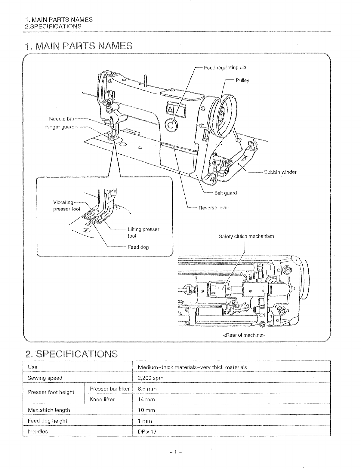
1.
MAIN PARTS NAMES
2.SPECIFICATIONS
1"
MAIN
Vibrating
presser foot
~-
lifting presser
foot
-~Feed
dog
Feed regulating dial
Safety clutch mechanism
<Rear
of
machine>
materials--very thick materials
-
1-
From the library of: Superior Sewing Machine & Supply LLC

3.WORK TABLE AND MOTOR
3.WORK TABLE AND MOTOR
Work Table
• When using a table made by another manufacturer, drill holes
in
the table
as
shown
in
the figure below.
• The top
of
the table should be 40
mm
in
thickness and should be strong enough to hold the
weight
and withstand the
vibration
of
the sewing machine.
Work
table
processing
diagram
14
Head
Motor mounting holes
!<:nee
lifter installation
position
Thread stand hole
A-A
cross section
B-B
cross section Oil pan installation position
15.5mm
Work Table
<Motor>
• All cords which are connected to the
motor
should be secured at least 25
mm
away from
any
moving
parts.
Furthermore,
do
not
excessively bend the cords or secure them too
firmly
with
staples, otherwise them
is
the
danger that fire or electric shocks could occur.
• Sek;ct
UiG
correct motor from those listecl
in
the table.
f{,:Jfor
to
the instruction manual for the motor for details on
installing and using the motor.
<M0tor pulley and
V-belt>
Select the correct motor pulley and V-belt by referring to the table
to
suit
the
power frequency of your area.
-2-
• Install the correct belt guard which
to the motor being used.
Power
Motor
motor
50
HZ
Motor
pulley 55
41
inches
2,000 spm
60HZ
Motor
pulley 45
41
inches
From the library of: Superior Sewing Machine & Supply LLC

4.
INSTALLATION
4.
INSTALLATION
o The sewing machine should only be installed
by a qualified technician.
• Ask your dealer or a qualified electrician for any
electrical
work
that may need to be done.
· The sewing machine
weights
more than 29 kg.
The installation should be carried out by
two
or
more people.
o Do not connect the
power
cord until installation
is
complete,
otherwise
the
m8chine
will
oper8te ifthe treadle is
prEJSSt)cl
by mistake,
v;hich could result in injury.
Be
sure to connect the ground. If the ground
connection is not secure, serious electric
shocks will result.
• Install the belt guard to the machine head.
4-1.
Installing the rubber hinge and the corner rubber
4~2.
Installing the oil pan
4-3.
Installing the machine head
--
3
1.
Install the rubber hinge
(1)
on the table
with
nails
(2
(Two places)
2.
Install the corner rubber Q) at the four corners
of
the
table
with
nails
Fit oil pan
with
4 nails into the opening
in
the table, and secure it
(Refer to the
work
table processing diagram on page
2.)
1.
Insert the
two
bed hinge connections
CD
into the holes
in
the machine bed.
2.
Fitthe bed hinge connection to the rubber hinge
and then place the machine head onto the corner
rubber
3.
Tap the head rest into the table hole.
NOTE:
Tap
the head rest securely into the table hole. If
the head rest
is
not pushed in
as
far
as
it will go,
the machine head will
not
be sufficiently stable
when
it is tilted back.
From the library of: Superior Sewing Machine & Supply LLC
4.
INSTALLATION
4~4.
Installing the spool pin.
4-5.
Installing the knee lifter assembly
-4-
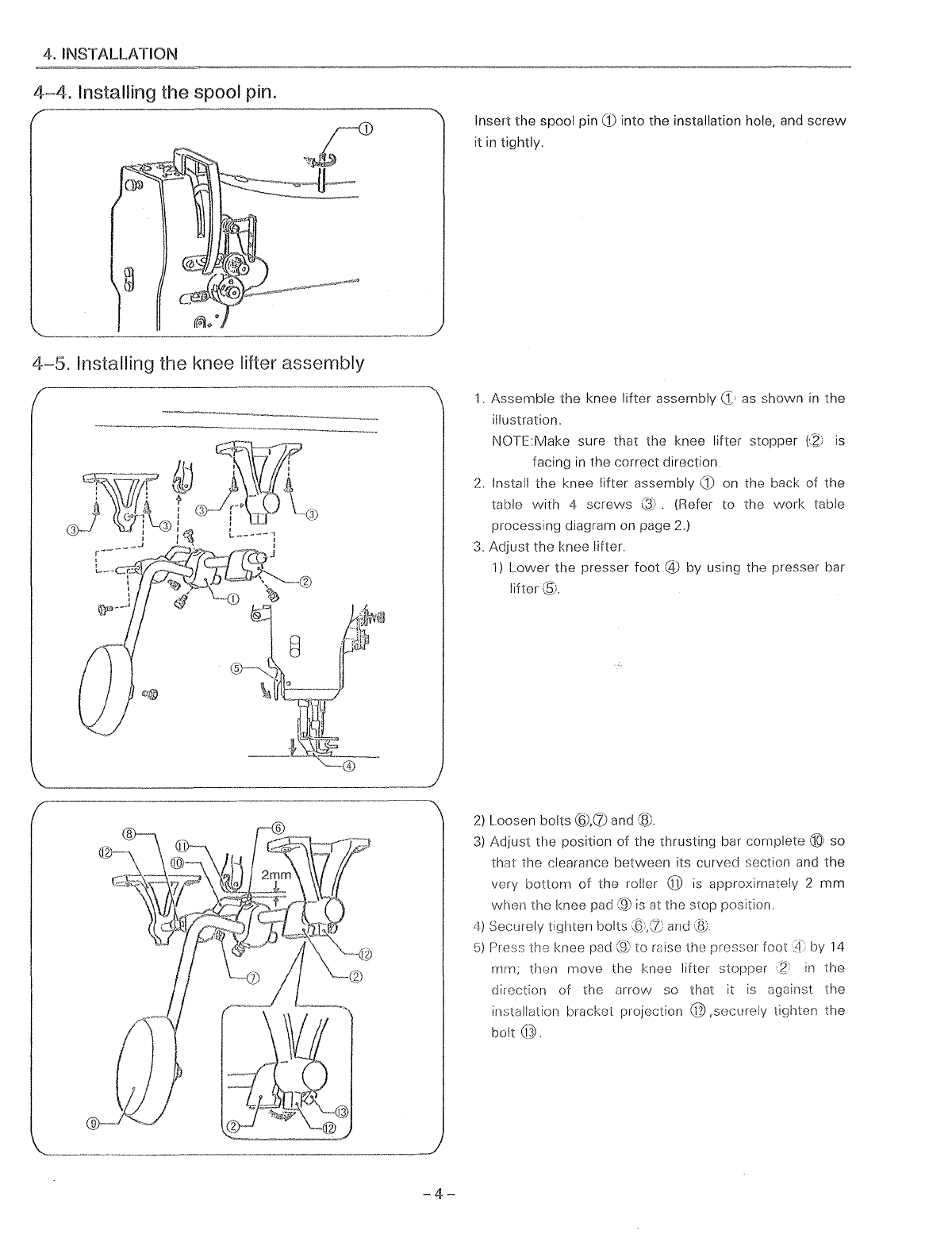
Insert
the
spool pin
CD
into the installation hole, and
screw
it
in
tightly.
1.
Assemble
the
knee lifter assembly as shown
in
the
illustration.
NOTE:Make sure that the knee lifter stopper
fZ:;
is
facing
in
the correct direction.
2.
Install
the
knee lifter assembly
CD
on the back of
the
table
with
4
screws
(Refer
to
the
work
table
processing diagram on page 2.)
3.
Adjust
the knee lifter.
1)
Lower
the
presser
foot
@
by
using the presser bar
lifter®.
2)
Loosen bolts
@.(1)
and
(til
3)
Adjust
the
position
of
the thrusting bar complete ® so
that
the
clearance
between
its curved section and
the
very
bottom
of
the
roller @ is approximately 2
mm
when
the
knee pad
(9)
is
at the stop position.
4)
Securely tighten bolts and
G)
Press the knee pad
to
mise the presser
foot
!f
by 14
mm;
then
move
the knee lifter stopper
:z
in
the
direction of the
arrow
so that it
is
against
the
installation bracket projection
@,securely
tighten
the
bolt@.
From the library of: Superior Sewing Machine & Supply LLC
4.
INSTALLATION
ling thH belt
4-7.
Installing the bobbin winder
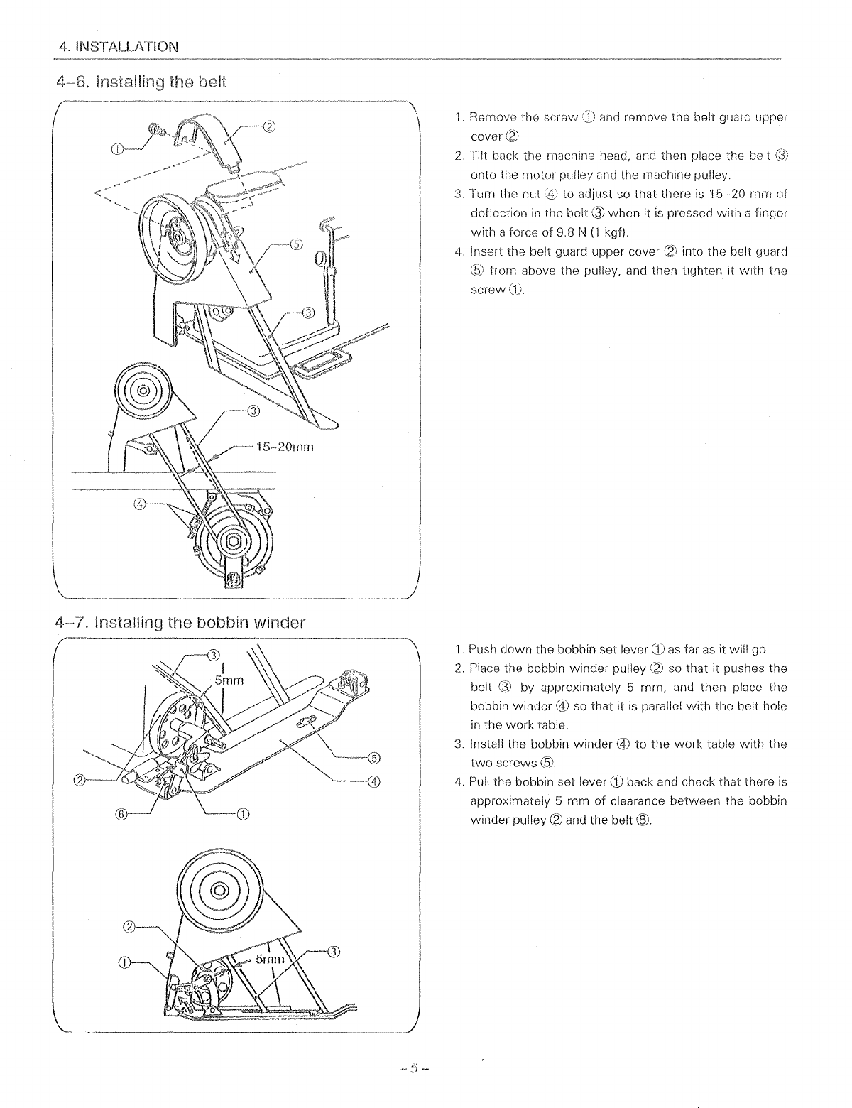
1.
Remove the screw
(1)
and
romove the belt guard upper
cover
2.
Tilt back the rnachine head, and then place the belt
onto the
motor
pulley and the machine pulley.
3.
Turn the nut to adjust so that there
is
15-20
mm
of
deflection
in
the belt Q)
when
it
is
pressed
with
a finQer
with
a force of 9.8 N
(1
kgf).
4.
Insert the belt guard upper cover into the belt guard
from above the pulley, and then tighten it vvith the
screw
1.
Push down the bobbin set lever
as
tar
as
it will go.
2.
Place the bobbin winder pulley so that it pushes the
belt by approximately 5 mrn, and then place the
bobbin winder @ so that it is parallel
with
the belt hole
in
the work table.
3.
Install the bobbin
winder@
to the
work
table
with
the
two
screws
@.
4.
Pull the bobbin set lever
GJ
back and check that there
is
approximately 5
mm
of clearance between the bobbin
winder pulley
(2)
and the
belt®.
From the library of: Superior Sewing Machine & Supply LLC

4. INSTALLATION
4~8.
Installing the belt guard (L)
4-9.
Installing the thread stand
1.
Tilt back the machine head, and then remove the
V-belt
from the
motor
pulley.
2.
While tilting the machine forward, insert belt guard(L)
G) into the belt guard
(2)
from underneath, and let
it
rest
there.
3.
Place the
V-belt
back onto the pulley.
4.
Install belt guard (L) G)
with
the
two
screws @ so that
there is no clearance between the belt guard
(2)
and
belt guard (L)
G)
(position@), and so that the reverse
lever @ and the belt guard
(2)
are
not
touching
(positions @ and ©).
Assemble the thread stand
as
shown
in
the illustration,
and then install
it
to the
work
table.
* Securely tighten the nut
CD
so
that
the thread stand
does not move.
From the library of: Superior Sewing Machine & Supply LLC

4. INSTALLATION
4-"10. Lubrication
•
Do
not
connect the
power
cord until lubrication has been completed, otherwise the machine may operate ifthe
treadle
is
pressed by mistake, which could result
in
injury.
•
Be
sure
to
vvear protective goggles
and
gloves when handling the lubricating oil, so that no oil gets into your
eyes or onto your skin, otherwise inflammation can
result
Furthermore, do not drink the oil under any circumstances,
as
it can cause vomiting and diarrhoea.Keep the oil
out
of
the reach
of
children.
The sewing machine should always be lubricated and the oil supply replenished before it
is
used for the first time, and also
after long periods
of
non-use.
Use only the lubricating oil.
• Add
1-2
drops
of
oil
in
the places indicated by the arrows.
Add oil to other sliding parts also, while being careful to avoid oil leaks.
Oiling
must
be done at least
twice
daily
in
continuous use.
-7-
From the library of: Superior Sewing Machine & Supply LLC

4. INSTALLATION
II
For oiling to hook
Remove the oil plug
CD
and pour oil until the oil surface reaches to the red line of the oil indicator
\2).
After pouring oil, tighten
the
oil plug
CD
securely.
Oiling adjustment to hook
Loosen the
nut®.
adjust oiling by adjusting
screw@.
To increase oil flow, loosen the adjusting
screw@,
to
decrease oil flow,
tighten the
screw@.
After
oiling adjustments completed, tighten the
nut®
securely.
4~
11. Checking the machine pulley rotating direction
Do
not
touch any
of
the moving parts or place any objects against the machine while sewing,
as
this may result
in
personal injury or damage
to
the machine.
-8--
1.
lnsertthe
power
cord plug into the wall
outlet
and then
turn
on
the
power
switch.
2.
Depress the treadle and check that the direction
of
rotation
of
the machine pulley matches the direction
of
the arrow
CD.
* If the direction
of
rotation
is
reversed, change the
direction
of
rotation
to
the correct direction while
referring to the instruction manual for the motor.
From the library of: Superior Sewing Machine & Supply LLC
5.
PREPARATION BEFORE SEWING
5.
PR
PARATION BEFOR SEWING
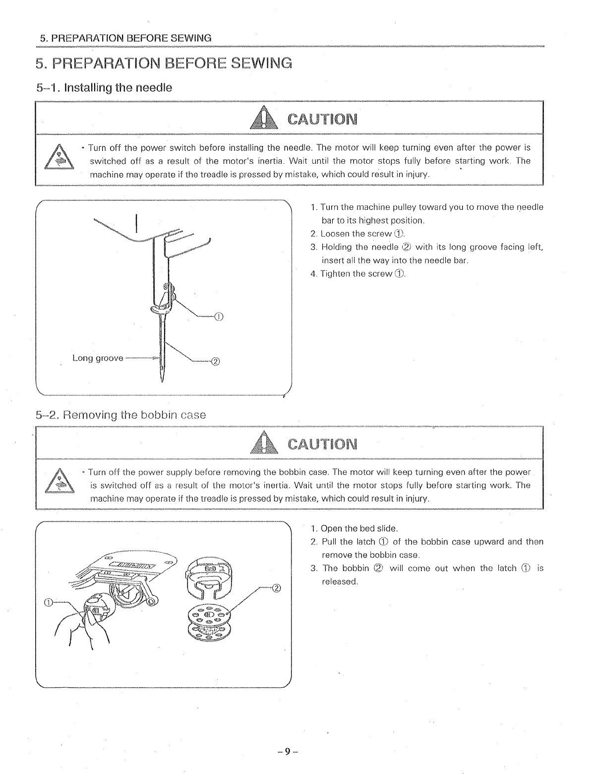
5-1
. Installing the needle
• Turn
off
the
power
switch before installing the needle. The
motor
will keep turning even after the
switched
off
as
a result
of
the
motor's
inertia. Wait until the
motor
stops fully before starting
machine may operate if the treadle
is
pressed by mistake, which could result
in
injury.
Long
groove-
~
5-2.
R£~moving
the bobbin case
1.
Turn the machine pulley toward you to move the needle
bar to its highest position.
2.
Loosen the
screw(!).
3.
Holding the needle
(2)
with
its long groove facing
left
insert all the way into the needle bar.
4.
Tighten the
screw
CD.
• Turn
off
the power supply before removing the bobbin case. The motor will keep turning even after the
power
is
switched
off
as
a result of the motor's inertia. Wait until the
motor
stops fully before starting work. The
machine may operate if the treadle
is
pressed by mistake, which could result
in
injury.
2
-9-
1.
Open the bed slide.
2.
Pull the latch
CD
of
the bobbin case upward and then
remove the bobbin case.
3.
The bobbin
(2)
will come
out
when
the latch
CD
is
released.
From the library of: Superior Sewing Machine & Supply LLC

5.
PREPARATION BEFORE SEWING
5~3.
Winding the lower thread
• Do not touch any
of
the moving parts or place any objects against the machine while winding the lower
as
this may result
in
personal injury or damage to the machine.
Thread winding amount
5~4.
Installing the bobbin case
1.
Turn
on
the power switch.
2.
Place the bobbinG:· onto the bobbin winder shaft
3. Wind the thread several times around the bobbin
<1·
in
the direction indicated the arrow.
4.
Push down the bobbin set lever Q).
5.
Raise
the presser foot
with
the presser bar lifter.
6.
Depress the treadle. Lower thread winding will then
start.
7.
Once .winding of the
lower
thread is completed, the
bobbin set
lever®
will return automatically.
* If the thread cannot be wound
on
evenly, loosen the
screw@_~
and move the bobbin winder bracket to the
side where there
is
less thread.
* Turn the adjustment screw
@j
to adjust the bobbin
winding amount.
To
increase the winding amount: Tighten the screw.
To
decrease the wincing amount: Loosen the screw.
Note:The amount of thread wound onto the bobbin
should
be
a maximum
of
80% of the bobbin
capacity.
• Turn
off
the
power
supply before installing the bobbin case.
The
motor will keep turning even after the power
is
switched
off
as
a result of the motor's inertia. Wait until the motor stops fully before starting work. The
machine may operate if the treadle
is
pressed by mistake, which could result
in
injury.
1.
While holding the bobbin so that the thread winds to
the right, insert the bobbin into the bobbin case.
2.
Pass
the thread through the slot
and
under the
tension spring
\21.
3.
Pull the thread
cut
through the hole
in
the end of the
tension spring
(2:.
4.
Check that the bobbin turns clockwise when the thread
is
pulled.
5.
Hold the latch
;.3;
on the bobbin case
and
insert the
bobbin case into the rotary hook.
6.
Close the bed slide.
From the library of: Superior Sewing Machine & Supply LLC

5.
PREPARATION BEFORE SEWING
5-5.
Threading
the
upper thread
CAUTION
• Turn
off
the power supply before installing the bobbin case. The motor will keep turning even after the power
is
switched
off
as
a result of the motor's inertia. Wait until the motor stops fully before starting work.
The
machine may operate
if
the treadle
is
pressed by mistake, which could result
in
injury.
5-6.
Adjusting
the
stitch
length
-11-
Turn the machine pulley and raise the thread take up lever
G:·
before threading the upper thread. This will make
threading easier
and
it will prevent the thread from coming
out
at
the sewing start.
Stitch length
can
be set by turning the feed regulating dial
Ci·.
Numeric figures on the dial
i.l'
show the stitch length
in
mm. The desired numeric figure
on
the dial should
be
set at just above, while depressing the revers lever
slightly.
From the library of: Superior Sewing Machine & Supply LLC

6.
SEWING
6.
"
Attach
all devices bofor:1 rnachir18. If the rnachine is used vvlthout these devices
attached, injury rnay result.
" Turn off the
powe;
switch
at the times. The
motor
will
turning evon
after
the; pnvver
is
sv\'itchcd
off
JS
a result
of
the
motor's
inertia.
Wait
until the rnmor
slops
fully before
rnayoperate if the treadle is
When
threading the needle by mistake,
which
could
msult
in injury.
When
replacing the needle and bobbin
When
not
using the machine and
when
leaving
the
machine unattended
vvork. The rnachine
• Do
not
touch any
of
the
moving
parts
or
place any objects against
the
machine
while
sewing,
as
this may
personal
injury
or
damage
to
the
machine.
6~1.
Sewing
Lower thread
6~2.
Backtacking
-12-
1.
While
holding
the
upper thread
with
your
fingers, turn
the machine pulley by hand
toward
you
until the
lower
thread
comes
out
onto
the
feed
dog.
2.
Pull the
lower
thread
toward
you
and check
that
it
pulls
out
smoothly,
3. Turn on
the
power
switch.
4. Depress the treadle
to
start
sewing,
When
the reverse lever is pushed,
the
material
feed
direction
will
be reversed, and
when
it
is returned
to
its
original position,
the
feed
direction
will
change back
to
normal.
From the library of: Superior Sewing Machine & Supply LLC

7.
THREAD TENSION
7.
THREAD TENSION
7
~
1.
Adjusting the thread tension
Upper thread
Lower thread
Lower thread
7
~2.Adjusting
the presser foot pressure
---------.
-
13-
Good even stitches
Upper thread tension too weak or
lower
thread tension
too strong
Upper thread tension too strong or
lower
thread tension
too weak
II
Upper thread tension
The tension
of
the upper thread
is
adjusted using the
tension thumb nut
G).
To
increase the tension
of
the upper thread,
·~urn
the
tension thumb nut
(f1
to the right.
To
decrease tension,
turn the tension thumb nut
<}1
to the left.
II
Lowerthread tension
CAUTION
Turn
off
the
power
switch before removing or
inserting the bobbin case.
The motor will keep turning even after the
power
is
switched
off
as
a result
of
the
motor's inertia. Wait until the motor stops
fully before starting work. The machine may
operate if the treadle is pressed by rl'istake,
which could result
in
injury.
Adjust by turning the thread tension
nut
(2J
until the bobbin
case will not drop by its
own
weight
while
the thread end
coming out
of
the bobbin case is held.
Adjust the presser foot pressure to
lower
as
much
as
possible
so
that the presser foot can properly hold down
material by turning the
screw
(f•.
From the library of: Superior Sewing Machine & Supply LLC

8.
STANDARD ADJUSTMENTS
8.
STAN ADJUSTMENTS
Maintenance and inspection
of
the sewing
machine should only be carried out by qualified
personnel.
Ask your dealer or a qualified electrician
to
carry
out
any maintenar.ce and inspection
of
the
electrical systern.
If any safety devices have been rernoved,be
sure
to
m-install
them to their
original positions and check that they operate
correctly before using the machine.
8-1.
Adjusting the thread controller spring
-14-
power cord from the wall outlet at the
times, otherwise the machine may operate if
treadle
is
by mistake, which could
in
injury. However, the motor will keep
even after the power
is
switched
off
as
a
the motor's inertia. Wait until the
fully before starting work.
When carrying out inspection,
maintenance
When replacing consumable parts
rotary hook
If the
power
switch needs
to
be
left
on
carrying
out
some adjustment. be
careful to observe
all
safety precautions.
Operating range
of
spring
The standard operating range for spring
CD
is
5-1
Omm.
1.
Loosen the
screw
\2·,
and then turn the thread con
troller spring stop
~
to adjust the operating range.
• For more operating range, move the spring stop
~~?!
to
the right.
• For less operating range, move the spring stop
Qi
to the
left.
2.
Tighten the
screw
(2_:.
Tension
of
the spring
The standard tension for spring
is
0.39-0.78
N (40-80g).
1.
Loosen the tension
thumb
nut
\4;
and
screw@.
2.
Turn the tension stud (§l to adjust the tension.
To
increase the spring tension, slightly turn the tension
stud ®!counterclockwise.
To
decrease the tension, turn the stud clockwise.
3.
After adjustment, tighten the tension thumb nut
0\)
and
screw\!?).
From the library of: Superior Sewing Machine & Supply LLC
8. STANDARD
ADJUSTMENT~;
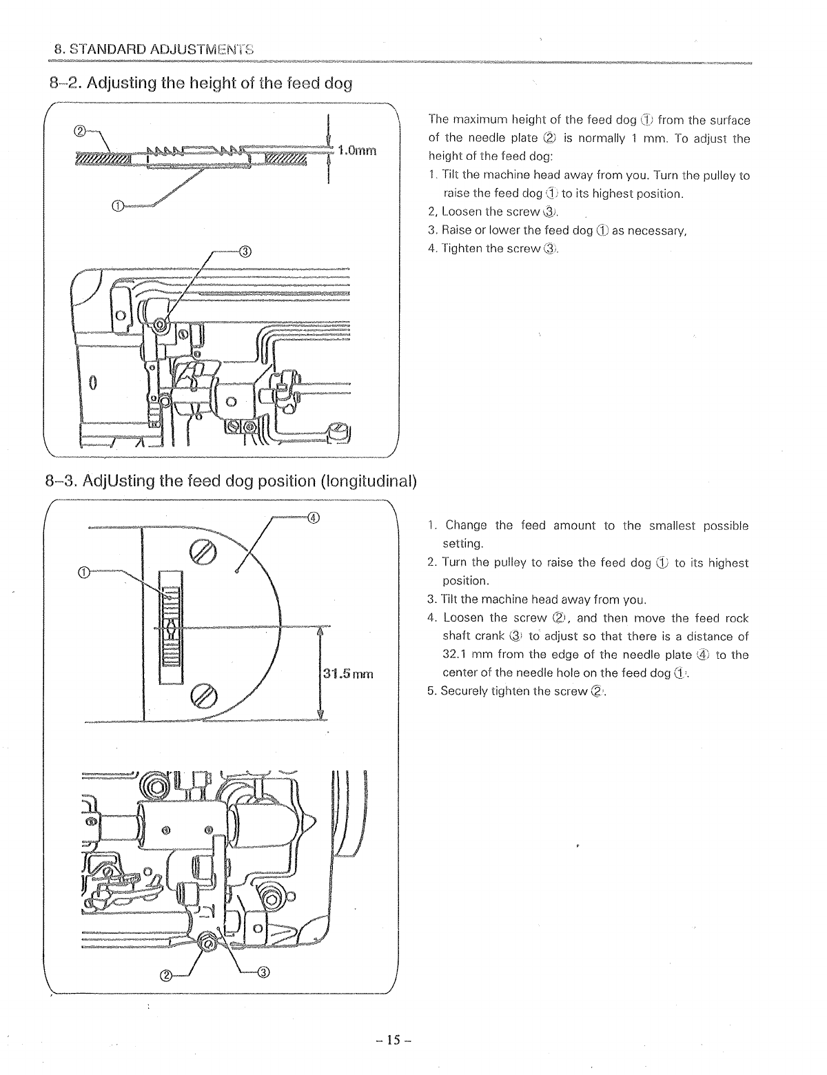
8~2.
Adjusting the height of the feed dog
8~3.
AdjUsting the feed dog position (longitudinal)
31.5mm
-
15-
The maximum height
of
the feed dog from the surface
of
the needle plate
(2)
is
normally 1 mm.
To
adjust the
height
of
the feed dog:
1.
Tilt the machine head away from you. Turn the pulley to
raise the feed dog to its highest position.
2,
Loosen the
screw~.
3.
Raise or lower the feed dog
CD
as
necessary,
4.
Tighten the
screw
Q
..
1.
Change the feed amount to the smallest possible
setting.
2.
Turn the pulley to raise the feed dog
position.
3.
Tilt the machine head away from you.
to its highest
4.
Loosen the screw (2), and then move the feed rock
shaft crank
~'
to
adjust so that there
is
a distance
of
32.1
mm
from the edge
of
the needle plate to the
center
of
the needle hole on the feed dog
(1•.
5.
Securely tighten the
screw
CZ·.
From the library of: Superior Sewing Machine & Supply LLC
Other manuals for 406RB-1
1
Table of contents
Other Chandler Sewing Machine manuals


Popular Sewing Machine manuals by other brands

KANSAI SPECIAL
KANSAI SPECIAL LX-SP Series instructions

Brother
Brother Upgrade KIT III Operation manual

Brother
Brother Innov-is NV1800Q Quick reference guide

Kenmore
Kenmore 19110 - Computerized Sewing Machine owner's manual

Brother
Brother Innov-is PC420 Operation manual

Butterfly
Butterfly M21 instruction manual


