Chandler 543 User manual
®
an
er
INSTRUCTION
BOOK
&
PARIS
BOOK
TACKERS
&
BUTTON
SEWERS
CLASSES:
543, 546, 548,
552, 554, 555, 558, 560,
600, 660, 710
cJ..ancller
~
CHAN
DL
ERM~HINE
CO
•
oyer,
mass.Ol432 u.
s.a
,
tel.
(617)
772
-
3393
From the library of: Superior Sewing Machine & Supply LLC

CURRENT PRODUCTION MODELS OF
CHANDLER CLASS 600 & 710 MACHINES
FLAT
BUTTON
SEWERS
...............Model 710-1 ...............................
16
stitch. side vih
..
auto
clamp lilt.
Model 710-5 ...............................
12
stitch. side vih.,
auto
clamp
lilt.
Model 710-10 .............................24 stitch, side vih
..
Model 710-35 .............................
16
stitch. hack & forth.
auto
ch1mp hft.
Model 710-55 .............................
16
stitch, cross (X) stitch.
auto
clump lift.
Model 710-85 .............................
12
stitch, back & forth,
auto
clamp lift.
Model 710-120 ...........................24
sti~ch,
square
pattern.
auto
clump lift.
HOOK
AND
EYE .............................Model 710-1HE ..........................
l6
stitch. side vib
.•
auto
clamp
lil1.
Modei710-5HE
..........................
l2
stitch, side vib.,
auto
clamp
lift.
WHIPPING
.......................................Model 710-12 .............................24 stitch. for whipping suit buttons.
NECKING .........................................Model 710-IN ............................
16
stitch. side vib.
SHANK
BU
ffON
SEWERS
............Model 710-IS .............................
16
stitch. side vib
..
side loading.
Model
71
0-5S .............................
12
stitch. side
vi
b
..
side loading.
Model710-50
.............................
12
stitch. hack & forth, front loading.
Model 710-65 .............................
16
stitch.
h<~ck
& forth, front loading. shank master.
TACKERS
.........................................Model 600-15 .............................6 stitch. back & forth
Model 600-25 .............................8 stitch, back & forth
Model 600-25S ...........................8 stitch, side
vih_-
Model 600-60 .............................6 stitch, side vih.
Model 600-75 .............................
12
stitch,
combination
vib.,
dmpery.
Model
600-750
..........................
12
stitch.
combination
vib..
dmpery
extra
hea
'Y
needle
Model 600-75K ..........................
12
stitch.
combination
vib., drapery knife thread
cutter
Model 600-75KD .......................
(both
of
above)
Model 600-95 .............................6 stitch,
combination
Vlb.
BONE
RING
.....................................
Model600-BR
............................
12
stitch, back & forth vib.
Model 600-BR.500 .....................
12
stitch, back & forth vih.
Yt
stroke
for
extra
large bone rings.
JOKERS
............................................
Model
600- .................................Special machines for
attaching
labels
and
other
removable objects. Normally modified square patterns.
BAR
TACK
.......................................Model 710-70BT ........................24 stitch zig-zag pattern.
HIG~
LIFT
.......................................
Model
658
or
758 .......................Full
~
inch bigger
stroke.
Designed
for
extra
large
shank
buttons.
Bulky tacking problems. etc. Specify
above
machine desired.
Change prefix from "600"
to
"651<".
NOTE: Any
of
the
above
machines may be
equipped
with a
built
in
knife mechanism. Add suffix
"K"
TWIN
NEEDLE
f
ACKER
...............Model 660- .................................8 stitch. back & forth,
Please specify needle gauges from
I~
-
2~
in
~,.
increments. Non adjustable.
STAND
..............................................Model 2Tc-600-l ........................Board only
Stand,
complete .........................
Complete
"H"
legs. I
IOV.
Stand
..........................................
Complete
"K"
legs. IIOV.
Stand
..........................................
Complete
"K"
legs. 220V.
CLAMPS
...........................................
Flat
button
Shank
button-
..
:-.;;
.......................Side loaaang ·
Shank
button
.............................
Front
loading
(shank
master)
Snap
...........................................Adjustable,
round
or
square
Snap
...........................................Non-adjustable, square.
Hook
and
eye
Whipping
Necking
Tacking
Tacking ......................................
Compensating
Bone ring ...................................
Compensating
Flat
button
.................................
Front
part
only
This
edltion
printed
10.1972
~----~------------~CHANDLER~--------------------
NOTE:
FOR
BUTTONROBOTS, HOPPERS,
AUTOMATIC
FEEDING DEVICES CONTACT
CHANDLER SALES & SERVICE CO.,
246
7th
AVE
.•
N.Y., N.Y.
10001
TEL.
212-226-7300
From the library of: Superior Sewing Machine & Supply LLC

MECHANICS
INSTRUCTIONS
THREADING DIAGRAM
:..
.....
INSTRUCTIONS
FOR
THREADING
Facing
the
Machine
as
shown in
the
illustration,
proceed
as
follows:
1 From Spool
A,
pass
thread
thru Spool
Stand
Arm
B.
2
Then
forward thru
Rear
Guide
Pin
·C.
3
Slide
thread
between
Rear
Tension
Disc
D on
the
left
hand
side
of
Tension
Post
E,
then to
the
right hand
side
of
Pin
F
as
above
in
detailed
view.
4
Repeat
step
number 3 for
Front
Tension.
5
Pass
thread
forward
t·hru
hole
in
Thread
Slack
Pull-of£
Lever
G,
Front
Guide
Pin
H
and
Thread
Guide I
in
top
of
Face
Plate.
6
Slide
thread
into
slot
J and down to
the
right
of
Pin
K.
7
Pass
down and around
Roller
in Lower Guide
Plate
L.
8
Insert
thru
Needle
Bar
Take-up
M
(left
to right).
9
Thread
under
Tension
Disc
Face
Plate
N.
10
Catch
thread
in
Needle
Bar
Thread
Guide
0 and
pass
it
thru
the
eye
of
the
Needle
from
front to
back.
(For
all models
having
Needle
Bar
Thread
Guide)
~--------------~CHANDLER~--------------~
CHANDLERl
From the library of: Superior Sewing Machine & Supply LLC

-CHANICS
IISTRUOIOIIS
TIMING
LOOPER
TO
NEEDLE
BAR
The
usual
procedure
for timing the Looper
and
Needle
Bar,
is
first
to time the Loop-
er
and then
set
the
height
of
the Needle
to
the point
of
the
Looper.
This
is
ac-
complished
as
follows:
1
Insert
new Needle
fuJl length
of
the
Needle
Bar hole and
tighten Screw A
(Fig.1)
2 As a preliminary
setting,
make
sure
the
point
of
the
Needle
is
approximately in
line
with the
center
of
the
Looper Shaft when the
Needle
Bar
is
at
the
1owest depth of
its
stroke.
FIGURE
1
t.Boftom
ol
(Neeel/e
Sirek
FIGURE
2
Adjustment
is
made by means
of
Screw B (Figure 1).
FIGURE
2A
3 Turn
the
machine by hand,
rotating
the
Looper
counterclockwise,
thus
raising
the Needle
5/32
of
an inch
from
the bottom
of
its
stroke
as
shown in
Figure
2.
At
this
time,
the
point
of
the
Lqoper
should
be
barely
visible
on
the
left
side
of
the
Needle
as
shown in
Figure
2.
To
adjust,
loosen
Screws C (Figure 3) and
rotate
Knurled
Looper
Holder
desired
amount in
either
direction.
Tighten
Screws C
securely.
4
There
should
be a
space
of
light
barely
visible
between the
point
of
the
Looper
and the
Needle
as
shown in
Figure
2A.
Adjust
for
proper
clearance
by
loosening
Screw D
(Figure
3) and moving
the
Looper
in
or
out the
desired
amount.
5 As a final
setting,
now
that
the Looper
is
properly timed in re-
lation
to
the
lift
(or up
stroke),
the Needle
Bar
can
be.
readjusted
(as
described
in
preceeding
item 2)
so
that
the point
of
the
looper
when
passing
the
Needle
is
approximately
1/32
of
an
inch
above
the
Needle
Eye.
This- final
setting
may
have
to
be
varied
slightly
depending upon
the
weight and
softness
of
the thread
or
material
being
used.
The
break
of
the
loop (or loop formation)
at
the
Needle
Eye
may
vary
according
to
the
thread
used.
This
will
possibly
require
setting
the
point
of
the
Looper
closer
or
further
from
the
eye
of
the
Needle but within a range
of
approximately
1/32
of
an inch.
----------------~CHANDLER~----------------
CHANDLER2
From the library of: Superior Sewing Machine & Supply LLC
MECHANICS
IISTRUOIOIIS
TIMING
THE
FINGER
Lateral
Setting
-(Controlled by Barrel
Cam
I,
Figure
3)
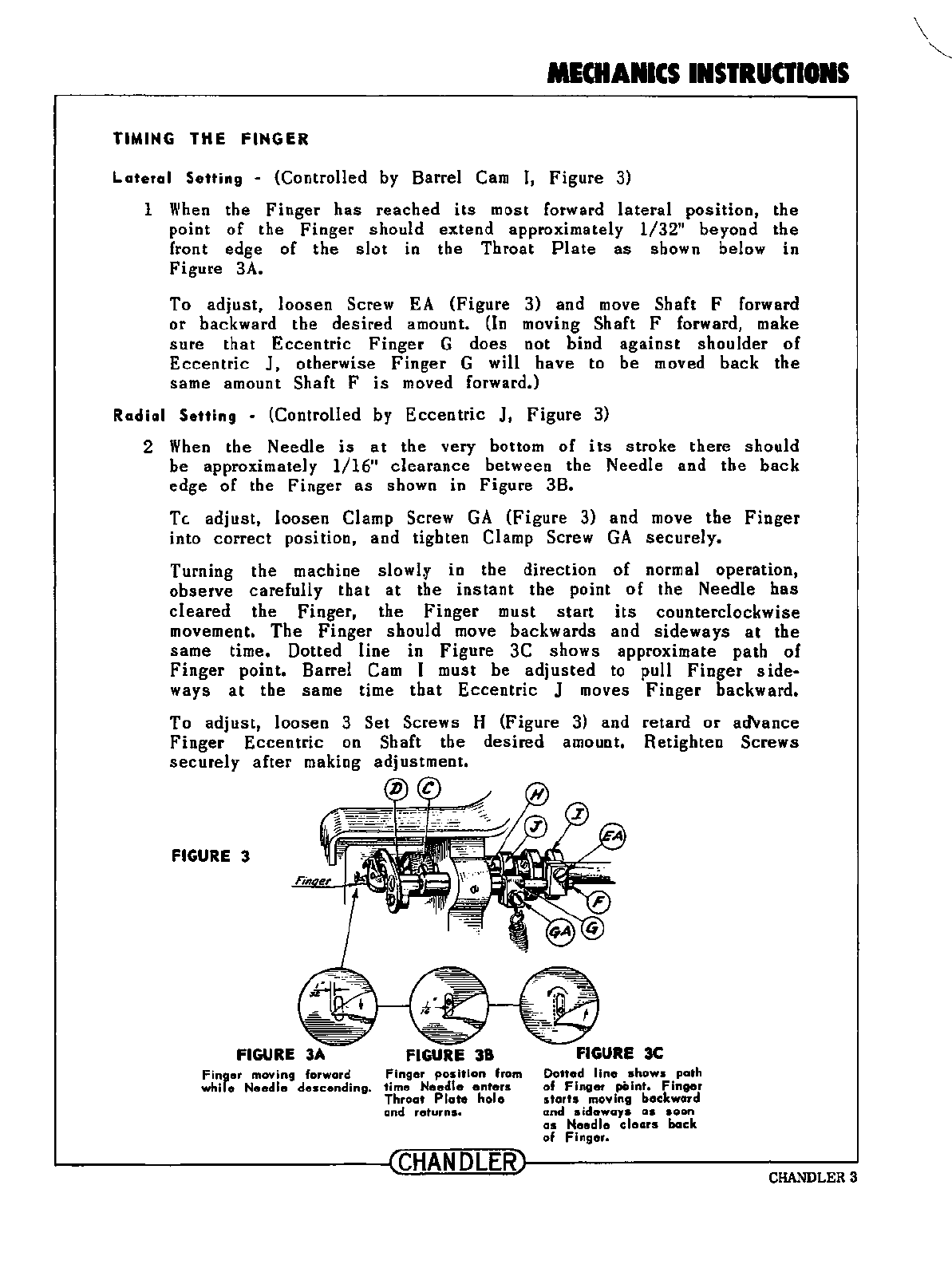
1
When
the
Finger
has
reached
its
most forward
lateral
position,
the
point
of
the
Finger
should
extend
approximately
1/32"
beyond
the
front edge
of
the
slot
in
the
Throat
Plate
as
shown below in
Figure
3A.
To
adjust,
loosen
Screw
EA
(Figure
3) and move Shaft F forward
or
backward
the
desired
amount.
{In
moving Shaft F forward, make
sure
that
Eccentric
Finger
G
does
not bind
against
shoulder
of
Eccentric
J,
otherwise
Finger
G will
have
to
be
moved
back
the
same amount Shaft F
is
moved forward.)
Radial
Setting
-(Controlled by
Eccentric
J,
Figure
3)
2
When
the
Needle
is
at
the very bottom
of
its
stroke
there
should
be
approximately
1/16"
clearance
between the
Needle
and
the
back
edge
of
the
Finger
as
shown in
Figure
3B.
Tc.
adjust,
loosen
Clamp Screw
GA
(Figure
3) and move
the
Finger
into
correct
position,
and
tighten Clamp Screw
GA
securely.
Turning
the
machine
slowlf
in
the
direction
of
normal operation,
observe
carefully
that
at
the
instant
the point
of
the Needle
has
cleared
the
Finger,
the
Finger
must
start
its
counterclockwise
movement.
The
Finger
should
move backwards and
sideways
at
the
same
time. Dotted
line
in
Figure
3C
shows
approximate
path
of
Finger
point. Barrel Cam I must be
adjusted
to pull
Finger
side-
ways
at
the same time
that
Eccentric
J moves
Finger
backward.
To
adjust,
loosen
3
Set
Screws H (Figure 3) and
retard
or
ad'vance
Finger
Eccentric
on Shaft the
desired
amount.
Retighten
Screws
securely
after
making
adjustment.
FIGURE
3
FIGURE
3A
FIGURE
38
Finger
moving forward
Finger
position
from
while
Needle
descending.
time
Needle
enters
Throat
Plate
hole
and
returns.
Dotted
II
ne
shows
path
of
Finger
point.
Finger
starts
moving
backward
and
sideways
as
soon
as
Needle
clears
back
of
Finger.
~--------------~CHANDLER~--------------~
CHANDLERS
\
~
From the library of: Superior Sewing Machine & Supply LLC

MECHANICS
INSTRUCTIONS
TH
R
EA
D
LO
CK
TIMING
ADJUST
MENT
\\'hen the
Needle
Bar
has
ascen
d
ed
to
within
1/8
or 5/
32
inch
from
the
hi
ghest
po
int
of
of
the
Needle
Bar
stroke
on
comp
le
tion
of
the
last
stroke
of
the
sewi
ng
cycle,
the
thr
ead
shou
ld
be
lo
cked
by
th
e
fo
rward
pr
essure
of
Plunger
A
against
PI
ate B
(Figu
re
1A).
The
Thr
ead
shoul d
be
l
ocked
wh
e n the m
ac
h-
ine
stops,
the
thread
br
ea
k when
is
1
ift
ed.
other
wi
se
will
not
the
Clamp
FIGURE lA FIGURE 1
C
au
t
ion
:
Excessive
pressure
of
th
e P l
unge
r on li
ght
or
w
eak
thre
ad
will
have
a t
ende
n
cy
to
frac
tur
e
the
thr
ead
causi
ng
excessive
t
hread
br
eakage.
To a
dju
st,
loose
n L
oc
k
Nu
t C
(F
igu
re
2)
and
turn Adj
usting
Screw
D in
or
out
the
des
ir
ed
amount.
Be
su
re
to
tigh
ten L
ock
Nut
C
secure
ly.
FIGURE 2
N o
te
: Machi
nes
are
usually
e
quipped
with
li
ght
Lo
ck
Spring
for
use
on light
thread
.
For
h
eavy
th
r
eads
us
e
heavier
Lo
ck
Spring
(See
Plate
1 ).
On r
esuming
the
first
st
r
oke
of
the
n
ew
sew
-
ing
cycle,
the
Thre
ad
L
ock
must
r
elease
the
thr
ead
some
time
befo
re
the
Ne
edle
Bar
reache
s
the
l
owest
point
of
the
s t
roke
so
that
the
t
hread
is
not
he
ld
ti
gh t
when
the
Take
-up E
(F
ig
ur
e 1)
above
s
tarts
i
ts
r
eturn
u
pward
s t
roke
.
Br
acket
F (
Fi
g
ure
12)
1s
provided
with
slots
so
t
hat
the
Tr
ip
Lock
Leve
r may
be
re
ta
r
ded
or
adv
an
ce
d for proper
ti
ming
.
~------
----
--------~CHANDLERr---
-
------------
--
--~
CHANDLER
4
From the library of: Superior Sewing Machine & Supply LLC
MECHANIC
INSTRUCTIONS
FIGURE 1
0
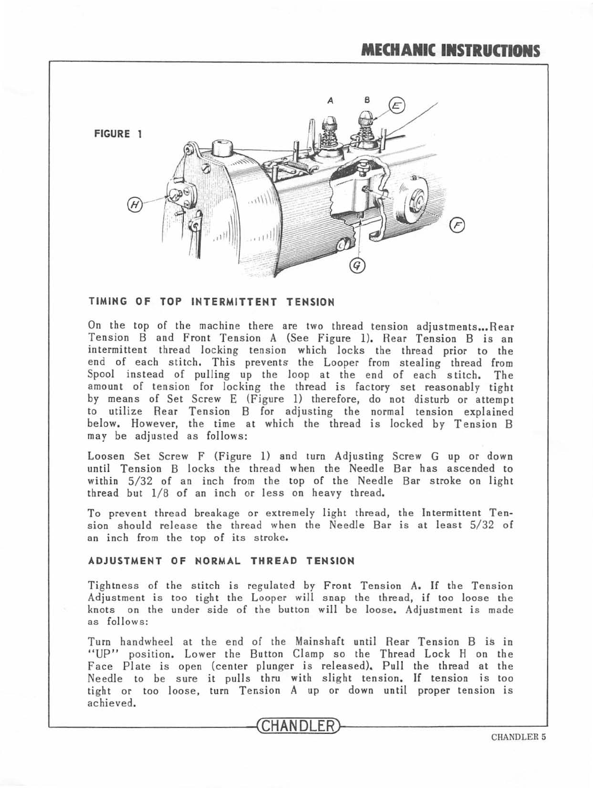
TIMING
OF
TOP
INTERMITTENT
TENSION
On the
top
of
the
machin
e th
ere
are two
thread
t
ens
ion
ad
justment
s
•••
Rear
Te
nsion
B
and
Front
Tens
ion
A (See
Fi
gure 1).
Rear
Tension
B
is
an
intermittent
thr
ead
lo
cking t
ens
ion
which
lo
cks
the
thr
ead
prior
to
the
e
nd
of
each
stitch.
Thi
s
pr
eve
nts the
Loop
er from s t
ea
ling
thr
ead
from
Spoo
l
instead
of
pulling
up
the l
oop
at
the
end of
each
stitc
h.
The
amo
unt
of
tension
for l
ock
ing
the
thr
ead
is
factory
set
reasonably
tight
by means
of
Set
Screw
E
(Figure
l)
therefore,
do
not
dist
urb or
atte
mpt
to
utili
ze
Rear
Tension
B for
adjust
in
g
the
n
orma
l
tension
expl
ained
b
elow.
However,
the time a t
which
the
thread
is
locked
by
Tension
B
may
be
adjusted
as
follows :
Loosen
Se
t
Sc
r
ew
F
(Fi
gure
l)
and
turn
Adjusting
Screw
G
up
or
down
until
Tension
B
locks
the
thr
ead
wh
en
the
Needle
Bar
has
asce
nd
ed
to
within
5/32
of
an
inch
from the top
of
the
Needle
Bar
s
trok
e
on
li
g
ht
th
re
ad
but
l/ 8
of
a n
inch
or l
ess
on
heavy
thread.
To
prevent
thread
breakage
or
ex
tr
eme
ly
li
ght
thread,
the
Intermittent
Ten-
sion
s ho
uld
r
elease
the
thr
ead
when
the
Needle
Bar
is
at
l
eas
t 5/
32
of
an
in
ch from th e
top
of
its
stroke
.
ADJUSTMENT
OF
NORMAL
THREAD
TENSION
Tightness
of
the
s
tit
ch is r
eg
ulated
by
Front
Ten
sio
n A.
If
the
Tension
Adjus tme
nt
is too
ti
g
ht
the
Looper
will
s n
ap
the t
hr
ead,
if
t
oo
l
oose
the
knots
on the
under
side
of
the
b
utt
on
will
be
l
oose.
Adjustm
ent
is
made
as
fol
lo
ws
:
Turn
handwheel
at
the
end
of
the
Mainshaft
until
Rea
r
Te
n
sion
B
is
in
"UP"
position.
Lower
the
Button
Clamp
so
the
Thread
Lock
H on
the
Face
Plate
is
open
(center
plun
ge
r
is
rele
ased
).
Pull
the
thread
at
the
Need
le to be
sure
it
p
ull
s
thru
with
slight
tension.
If
ten
sion is
too
tight
or
too l
oose,
turn
Tension
A up
or
down
until
prop
er
tension
is
achieved
.
~------
----------
--~CHANDLER~
--
----------------~
CHANDLER 5
From the library of: Superior Sewing Machine & Supply LLC
MECHANICS
INSTRUOIONS
FIGURE 1
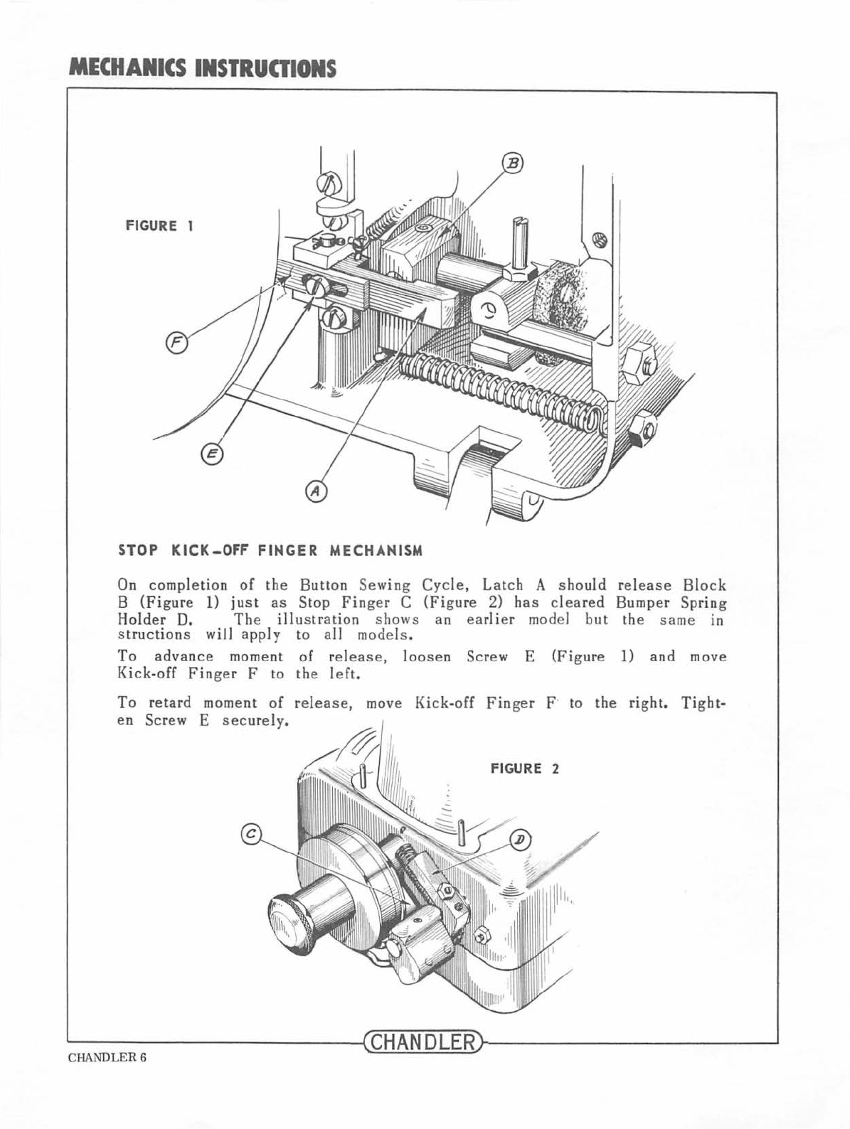
STOP
KICK-OFF
FINGER
MECHANISM
On
completion
of
the
Button
Sewing
Cycle,
Latch
A
shou
ld
release
Block
B
(Figure
1)
just
as
Stop
Finger
C
(Figure
2)
has
cleared
Bumper
Spring
Holder
D. The
illu
stration
shows
an
earlier
model
but
the
same
in
st
ruction
s will
apply
to all models .
To
advance
moment
of
rel
ease,
loo
se
n
Screw
E
(Figure
1)
and
move
Kick-off
Finger
F
to
the
l
eft,
To
retard
moment
of
release,
move
Kick-off
Finger
F· to
the
right.
Tight-
en
Screw E
securely.
FIGURE 2
~----------------~CHANDLER~----------------
~
CHANDLER 6
From the library of: Superior Sewing Machine & Supply LLC
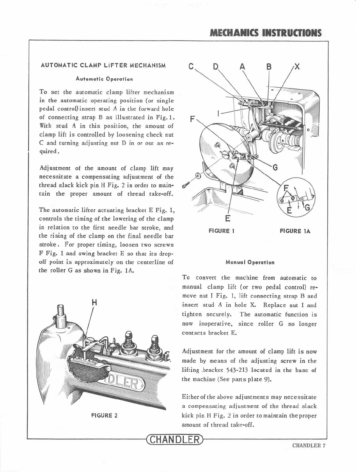
AUTOMATIC
CLAMP
LIFTER
MECHANISM
Automatic
Operation
To
s
et
the
automatic
clamp
lift
er
mechanism
in
th
e automatic
operating
po
s
it
ion
(or
s
in
gle
pedal
contro
l)
insert
stud
A
in
th
e forward hole
of
connecting
strap
B
as
illu
s
trat
ed
in
Fig.
1.
With
st
ud A
in
this
pos
ition
, the amount
of
clamp
lift
is
controlled
by l
oose
ning ch
eck
nut
C a
nd
turning adj
ustin
g nut D
in
or out
as
re-
quired,
Adjustment of
the
amount
of
cl
amp
lift
may
n
ecessi
tate
a
compensating
adjustment
of
the
thread
s
lack
kick
pin H
Fig.
2
in
ordet
to main-
tain
the
proper amount of thr
ea
d
take-off.
The
automat
ic
lifter
actuatin
g br
acke
t E
Fig.
1,
controls
the timing of
the
lo
wer
in
g of
the
clamp
in
rel
ation
to th
e first
needle
bar
scroke, and
the
rising
of
the
clamp on
the
final
ne
ed
le
bar
s
troke.
For
proper timing, loo
se
n two
sc
rew
s
F
Fig.
1 and
swing
bracket E so
th
at
it
s drop-
off
point
is approxim
ately
on the
centerli
ne
of
the
roller
G
as
shown
in
Fig.
1A
.
FIGURE 2
MECHANICS
INSTRUCTIONS
FIGURE 1 FIGURE
lA
Manual
Operation
To
convert
th
e m
ac
hine from
automatic
to
manual
cl
a
mp
lift
(or two
peda
l
contro
l) re-
mov
e nut 1
Fig.
1,
lift
connecting
st
rap B
and
insert
st
ud
A
in
hole
X.
RepLace nut I and
tighten
sec
urely.
Th
e
automatic
function
is
no
w
inoperative,
s
tnce
roller
G no
longer
contacts
bracket
E.
Ad
ju
stment
for the amount of clamp
lift
is now
made by
me
ans of
the
a
dju
sting s
crew
in
the
li
f
tin
g .bracket 543-213
lo
cated
in
the b
ase
of
the m
ac
hin
e
(See
parts
plat
e
9).
Ei
ther
of
the
above
adjustments
may ne
cess
itat
e
a compen
sat
in
g
ad
ju
st
ment of
the
thread
sl
ack
kick
pin
H
Fig.
2 in order to maintain
the
proper
amo
unt of thr
ead
take
-off.
~--------------~C
HANDLER~----------
------~
CHANDLER 7
From the library of: Superior Sewing Machine & Supply LLC
BASIC
COMMON
PARTS
I
2857-95
1
543-33
8
543
-
32
10
543-31
11
543-28
12
543
-
27
/8
19
20
21
22
23
543-37
24
54
25
26
543-
CHANDLER 8
CHANGES: 08
.1
972
1.
was
543
-1
002A
2.
was
543-35
3.
was
543-35
4.
was
543-84
5.
was
543-1002A
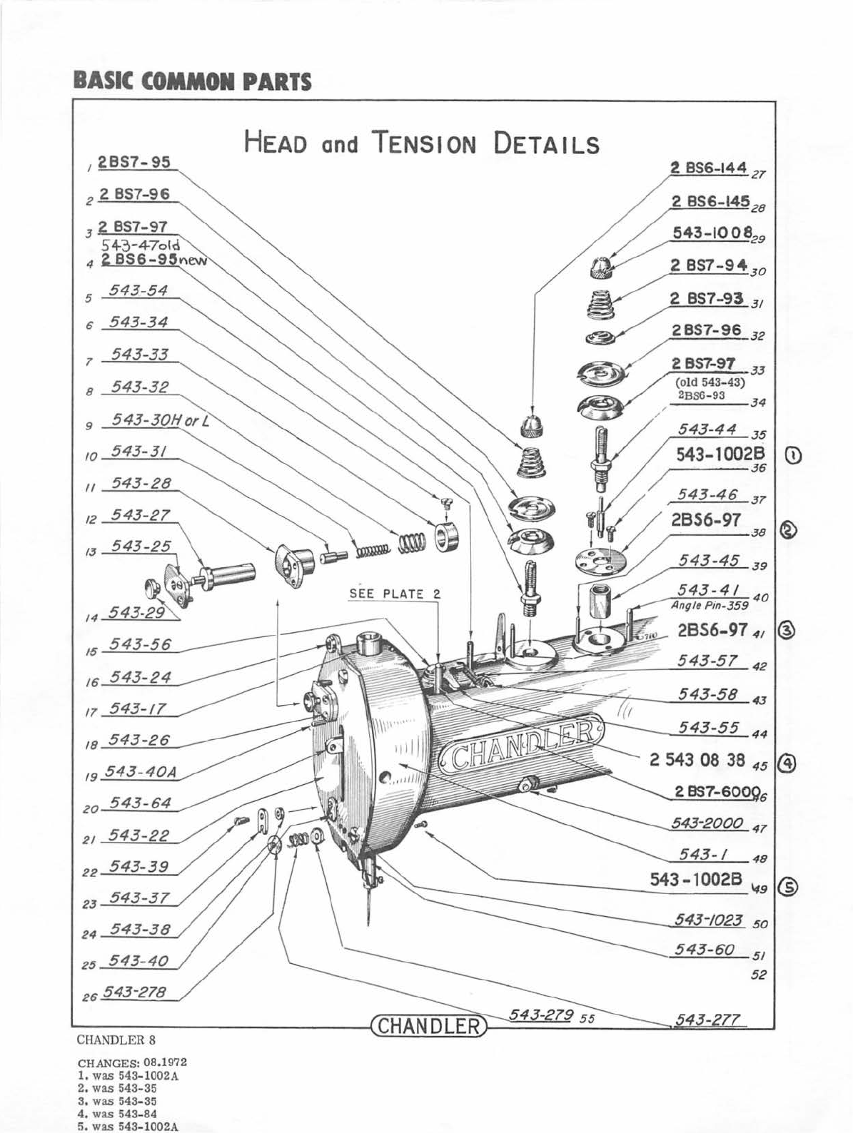
HEAD
and
TENSION
DETAILS
2
856-144
21
2
857-93
31
~32
.
S
EE
PLATE
2.
2
857-97
33
(old
543-
43)
2BS6-
93
34
From the library of: Superior Sewing Machine & Supply LLC
I
543
-
/006
2
543-69
7
543
-
64
8
543-65
9 543-1010
II
12
13
14
Nudls
No.7
Hsa1
No.5
Ligh
15
16
543-200/
17
18
/9
20
21
22
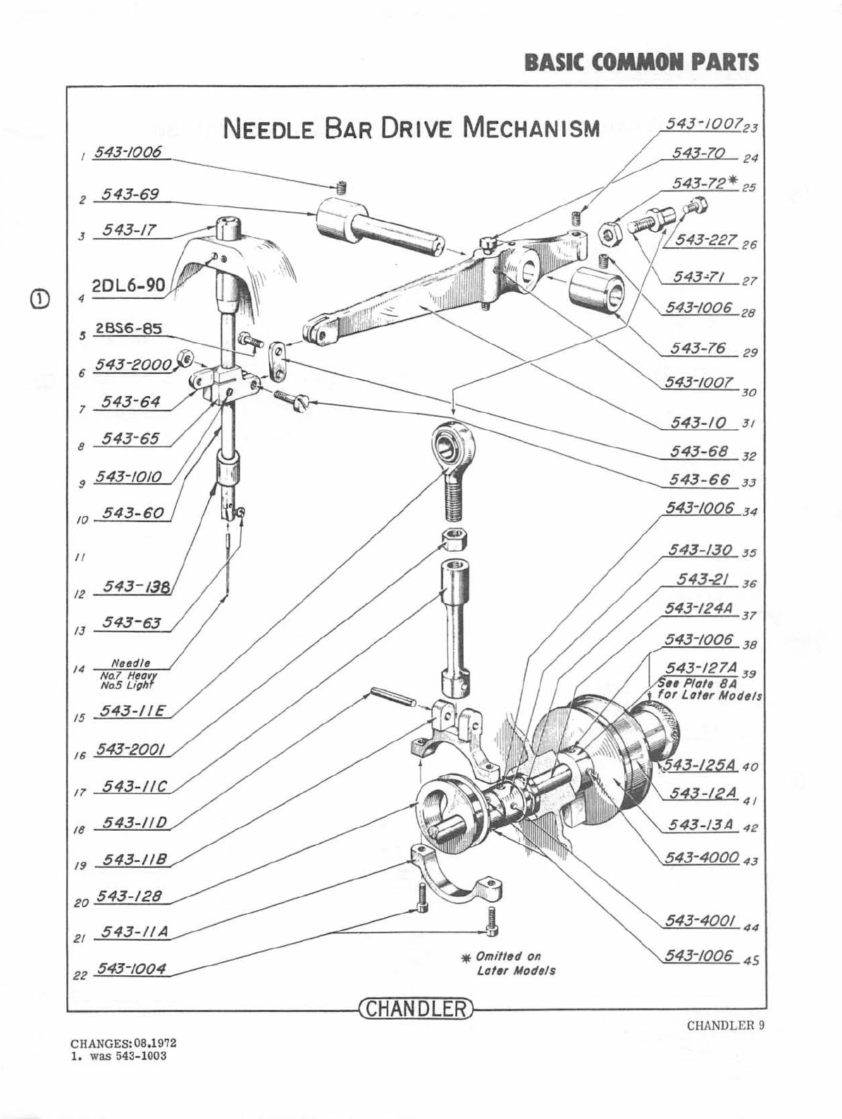
BASIC
COMMON
PARTS
NEEDLE BAR
DRIVE
MECHANISM
*
Omitted
on
Later
Models
543-10
543-68
543-66
3 /
32
33
34
35
36
37
38
~----------------~CHANDLERr-----------------~
CHANGES:08.1972
1.
was 543-1003
CHANDLER 9
From the library of: Superior Sewing Machine & Supply LLC
®
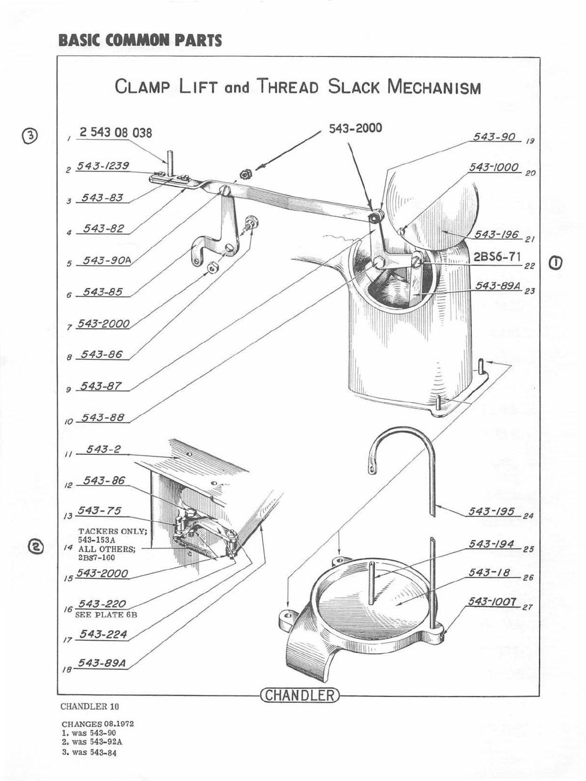
BASIC
COMMON
PARTS
CLAMP
LIFT
and
THREAD SLACK MECHANISM
2 543 08 038
8
9
10
II
12
15
.....:::5;__;4...:::..3.......:-8::....::9...:...:A._,
18-
CHANDLER
10
CHANGES
08.1972
1.
was
543-90
2. was 543
-92A
3.
was
543-84
' I
24
25
26
27
From the library of: Superior Sewing Machine & Supply LLC
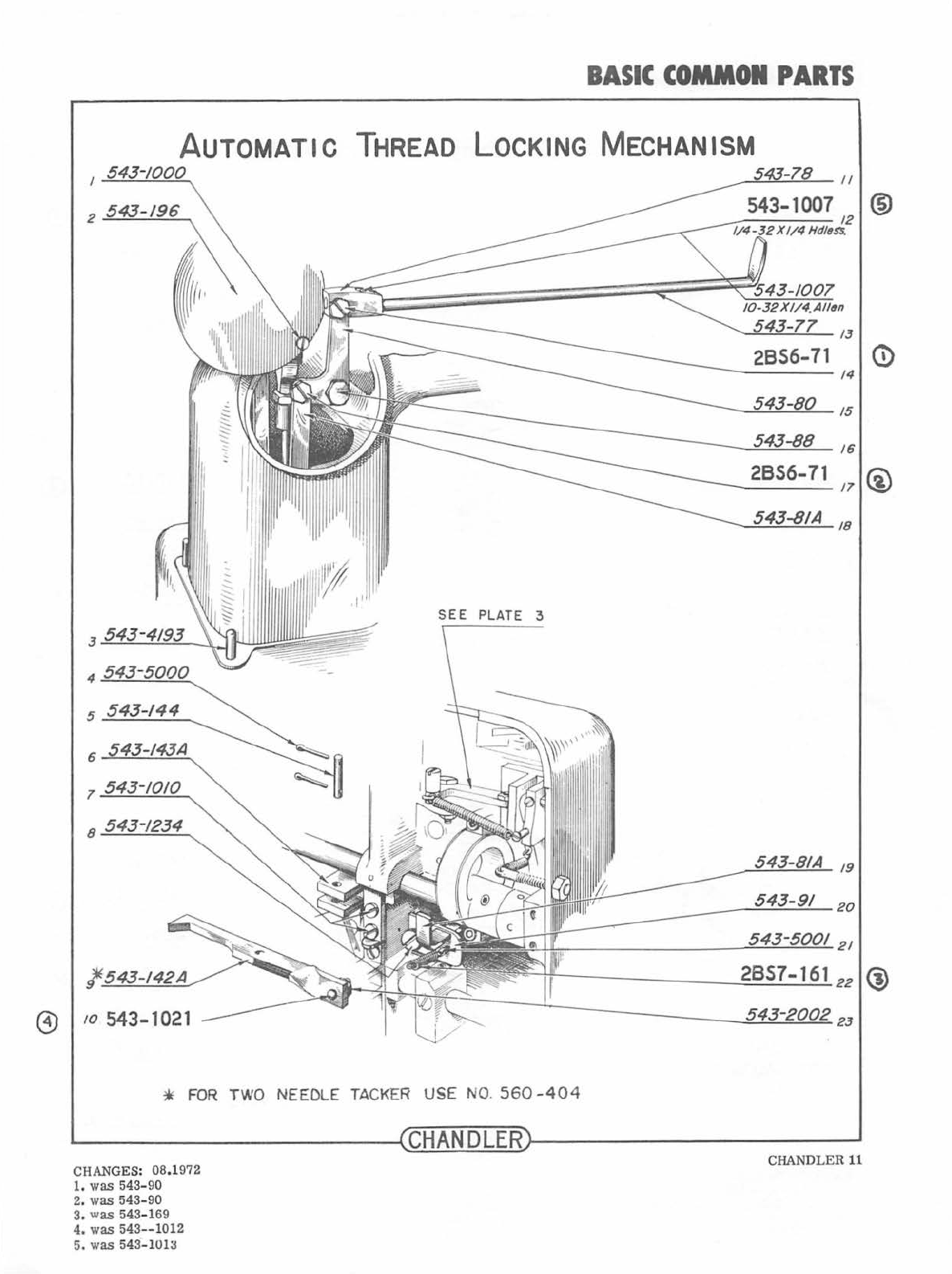
BASIC
COMMON
PARTS
AUTOMATIC
THREAD LOCKING MECHANISM
2
543-/96
13
0
14
15
16
2856-71 @
/1
/8
SEE
PLATE 3
5
543-144
6
1
8
/9
20
21
l.
2857-161
22
®
@
/0
543-1021 23
*
FOR
TWO NEEDLE T
AC
K
ER
U
SE
NO.
5
60
-40
4
CHANDLER
CHANGES:
08.1
972 CHAN
DLER
11
1.
was
543-90
2.
was
5
43-90
3.
was
54
3-169
4. was
543--
1012
5. was
5
4
3 -
10
1
~
From the library of: Superior Sewing Machine & Supply LLC
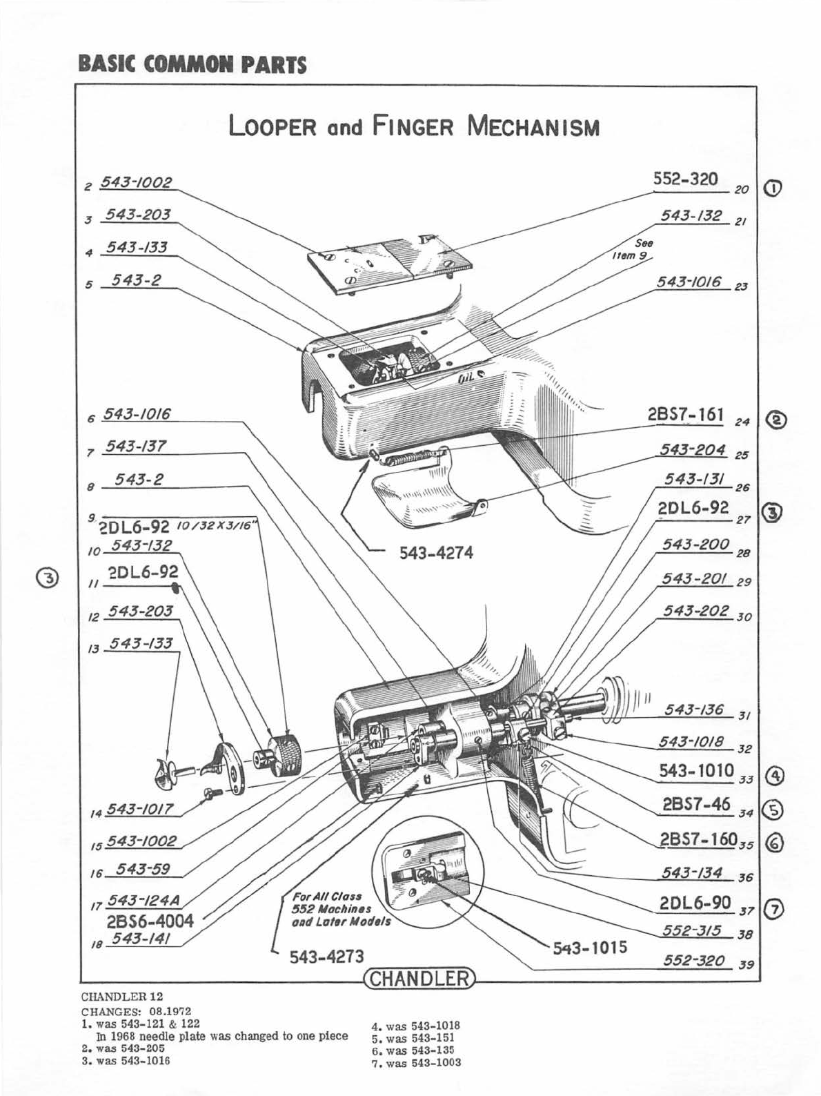
G>
B
ASIC
CO
MMON
PARTS
LOOPER
and
FINGER MECHANISM
2
543
-
1002
6
7
543-137
8
543-2
10
II
17
543-!24A
2856-400
4
18 543-141
CHAND
LER
12
CHANGES:
08.
1972
1.
was
543
-1
21 & 122
543-4273
In
1968
nee
dl
e plate was
chan
ge
d
to
one pi
ece
2.
was
543- 205
3. was 54
3-
1016
--C-HA_N
__
D~L-=E=--R
4. was 54
3-
1018
5.
was
543-15
1
6.
was
543-135
7.
was
54
3-
1003
552-320
20
<D
543
-
/32
21
2857-
161
24
®
25
26
®
29
20L6-90
JT
(J)
552-315
38
552
-
320
J9
From the library of: Superior Sewing Machine & Supply LLC

CD
®
BASIC
COMMON
PARTS
1
552-336
FoR
CLAss 552
AND
LATER MoDELS
543-326
22
552-328
2J
7
552-325
8
543-187
9
543-209
543-10028
II
543-330
/J--!:::....:..:::_-.=2
_
___
----.,
552
-
337
24
543-1002825
543-
28
JO
J/
No
Shouldu
(N~w
Sly!~)
543-140;-:A
-
~
---
~~
§.j_~'Qg?._~,B
Sho
ulder
Stud
543-140
~----------
--
----
~
~C~H~AN~D~L~E~R~
--------
--------~
CHANGES:
08
.1972 CHANDLER
13
1.
was
552-329
2.
was
543-1002A
3.
was
543-184
Q)
From the library of: Superior Sewing Machine & Supply LLC

CD
<D
@
BASIC
COMMON
PARTS
12
------..
552-313
13 543-1010
16
543-/9A
2BS7-161
17
-------,.
STOPPING MECHANISM
NOTE: BELOW SPRING
STOP
DISCONTINUED
IN 1948.
SEE
FOLLOWING PAGES
FOR
LATER
MODIFICATIONS.
NEEDLE TACKER
*
USE
NO.
560-402
T
USE
N0.560-403
L------------------4CHANDLER~--
------
--------~
CHANDLER
14
CHANGES: 08.1972
1.
was
543-169
2.
was 543-20
3.
was
543-1018
4.
was
543-235
(a!ter
1970,
"C"
clips
used)
From the library of: Superior Sewing Machine & Supply LLC

BASIC
COMMON
PARTS
STOPPING
MECHANISM
FoR
CLASS
552
MACH.
2 543 08 036
4
52-4000
5
552-1006
INTRODUCED 1952
543-391
7~~-~4~0~0~0--------~~
-
8~~~0~0~6
·
------~~------~
-
*_5::....;5::....:;2:..._-.=....3:....::1
8"-/
II
12
552-1010
FOR
TWO NEEDLE
TACKER
*
USE
NO.
560-429
t
USE
NO.
560-
403
552-33514
552-3002
'
15
552-309
16
~------------------~CHANDLERr-----------------~
CHANDLER 15
CHA
NGES: 08.1972
1. was 543-311,
also
see
assy
dwgs
From the library of: Superior Sewing Machine & Supply LLC

BASIC
CO-ON
PARTS
STOPPING
MECHANISM
FOR
CLASS
600
MACHINE
INTRODUCED 1971
~-----------600-335
~~---------552-3002
~~---------600-309
600-332A
WASHER
FOR
THOSE
WISHING
TO
CONVERT
THEIR
CLASS
552
CUSHIONSPRING
HOLDERS,
PART
NO.
600-323
ADAPTER
MUST
BE
PURCHASED.
(spring
no.
552
-332
will
be
discontinued.
)
CLASS
552
REBOUND
FINGER
STOP
GUIDE
(552-309)
WILL
BE
REPLACED
BY
A
NEW
ONE
(
600
-
309)
,
WHICH
IS
HEAVIER.
NEW
SCREWS
MUST
ALSO
BE
PURCHASED
(600-
335).
SEE PAGE 34
FOR
ASSEMBLY NUMBER
FOR
COMPLETE
UNIT.
~----------------~CHANDLER~--------------~~
CHANDLER16
CHANGES: 08ol972
1. was 552-311. also see assy dwgs
From the library of: Superior Sewing Machine & Supply LLC

BASIC
COMMON
PARTS
TREADLES
and
TRIP
LEVERS
<D
543-94 2855-177
/6
g)
2
543
-
213
543-2002
17
3
543-2002
543
-1018
18
4
543
-10
/9
543-2002
19
5
543-10/9
543
-
1021
20
®
6
21
7
543
-200
2 2
8
9
1010
24
25
II
26
/2
27
13
543-226
28
14
29
15
30
~--
--
------
----
--~~
CHruA~N~D~L&E~Rr---
--
----
------
--~
CHANDLER
17
CHANGES: 08.1972
1.
was 543
-9
3
2. was
54
3-7
9
3.
was B
S-7
7
4.
was 543-1019
From the library of: Superior Sewing Machine & Supply LLC

®
OPTIONAL
-
NOT
FOUND
ON
ALL
MACHINES
AUTOMATIC
CLAMP
LIFTER
GROOVE
PIN
4
555-380
5
6
7
555-377
8
543-3001
543-1023
9
II
555-382
555-387
13
.
555-381
14
543-2000
15
543-220A
543-2005
552-367
555-378
/6
555-379
17
543-200018
555-383
19
543-241
2 0
~
--
--------------~CHANDLER~------------------~
C
HA
NDLER 18
CHANGES: 08
.1
972
1. was 543
-101
6
2. was 543
-101
8
From the library of: Superior Sewing Machine & Supply LLC
This manual suits for next models
10
Table of contents
Other Chandler Sewing Machine manuals


