Chandler DARNER User manual
OPERATING
INSTRUCTIONS
for
the
CHANDLER
DARNER
All
Models
ckax:dler
Mi-..-.
Ayer,
CO.
From the library of: Superior Sewing Machine & Supply LLC

KNOW
YOUR
DARNER!
Read
these
instructions
carefully
and
thoroughly
before
operating
machine.
From the library of: Superior Sewing Machine & Supply LLC

CHANDLE
A -
Top
Thread
Tension
K -
Motor
B -
Take-up
Lever
L -
Bobbin
Winder
C -
Top
Thread
Guide
M -
Bobbin
Winder
Tension
D -
Face
Plate
N -
Thumb
Screw
for
Thread
Hook
Tilting
Head
E -
Needle
Bar
O -
Hand
Wheel
Thread
Guide
P -
Spool
Pin
(Rear)
F -
Presser
Foot
Lifter
Adjustment
R -
Take-up
Spring
G -
Needle
Clamp
Screw
S -
Latch
Sleeve
H -
Presser
Foot
T -
Presser
Foot
1 -
Spool
Pin
(Front)
Thumb
Screw
From the library of: Superior Sewing Machine & Supply LLC
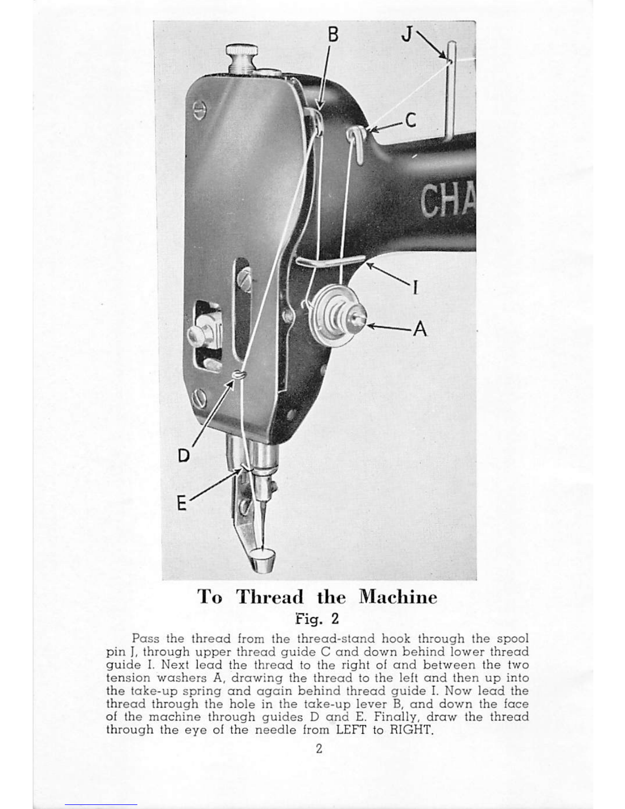
To
Thread
the
Machine
Fig.
2
Pass
the
thread
from
the
thread-stand
hook
through
the
spool
pin
I,
through
upper
thread
guide
C
and
down
behind
lower
thread
guide
I.
Next
lead
the
thread
to
the
right
of
and
between
the
two
tension
washers
A,
drawing
the
thread
to
the
left
and
then
up
into
the
take-up
spring
and
again
behind
thread
guide
I.
Now
lead
the
thread
through
the
hole
in
the
take-up
lever
B,
and
down
the
face
of
the
machine
through
guides
D
and
E.
Finally,
draw
the
thread
through
the
eye
of
the
needle
from LEFT to RIGHT.
From the library of: Superior Sewing Machine & Supply LLC
To
Remove
the
Bobbin
Turn
the
hand
wheel
toward
you
imtil
the
needle
bar
is
in
its
uppermost
position.
Then
lift
up
on
latch
A
(Fig.
4)
located
under
the
nickeled
sleeve
S
on
the
mend
ing
arm.
This
allows
the
bobbin
case
holder
to fall
back
on
its
hinge
releasing
the
bobbin
case.
Lift
up
hinging
clamp
F (Fig. 3)
with
the
fingernail
and
shake
out
the
bobbin.
To
Wind
the
Bobbin
To
wind
the
bobbin,
place
it
on
the
spindle
of
the
bobbin
winder
L(Fig. 1).
Now
lead
the
thread
from
the
guide
pin
I
down
the
front of
the
machine,
to
the
left
of
and
between
the
tension
discs
M,
and
up
to
the
bob
bin.
Wind
the
thread
around
the
bobbin
a
few
times
by
hand,
and
then
raise
the
bobbin-winder
unit
against
the
hand
wheel
belt.
The
tension
spring
will
hold
it
in
this
position.
Then
release
the
hand
wheel
for
winding
the
bobbin,
by
placing
your
left
hand
on
the
hand
wheel
and
with
your
right
loosening
the
hand
wheel
knob,
a
quar
ter
turn
toward
you
or
until
it is free.
This
will
allow
the
hand
wheel
to
turn
without
running
the
rest
of
the
ma
chine.
After
the
bobbin
has
been
wound,
the
knob
must
be
retightened.
If
the
machine
is
already
threaded,
the
operator
may
save
rethreading
the
machine
by
winding
the
bobbin
by
the
following
alternate
method:
1.
Release
thread
tension
by
raising
the
hand
lifter
W(Fig. 8).
2.
Then,
remove
the
thread
from
the
needle
and
draw
the
thread
from
the
last
thread
guide
E(Fig. 2) to
the
tension
discs
M
and
up
to
the
bobbin
on
the
winder
arm.
Always
lower
the
bobbin
winder
unit
to
save
un
necessary
wear
against
the
belt.
From the library of: Superior Sewing Machine & Supply LLC
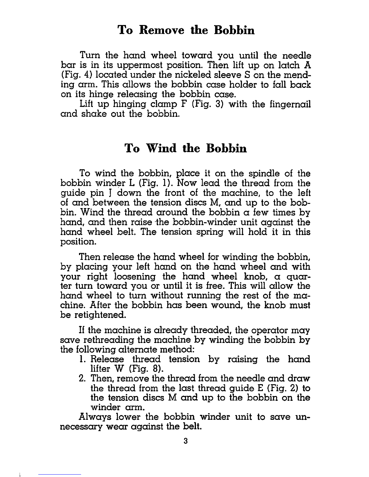
Fig.
3
To
Thread
the
Bobbin
Case
Hold
the
bobbin
in
the
right
hand
between
the
thumb
and
forefinger
with
the
thread
drawing
off
at
the
bottom
toward
the
right.
With
the
left
hand
hold
the
bobbin
case
with
the
hinge
"F"
opened.
Now
insert
the
bobbin
on
the
center
stem
E,
draw
the
thread
through
slot
D
and
under
the
tension
spring
C.
Care
should
be
taken
to
see
that
the
thread
is
under
the
spring.
From
the
spring,
lead
the
thread
to
the
projection
on
the
bobbin
case
and
draw
it
through
the
hole
B.
The
bobbin
case
is
now
threaded
and
ready
to
be
placed
in
the
machine.
From the library of: Superior Sewing Machine & Supply LLC
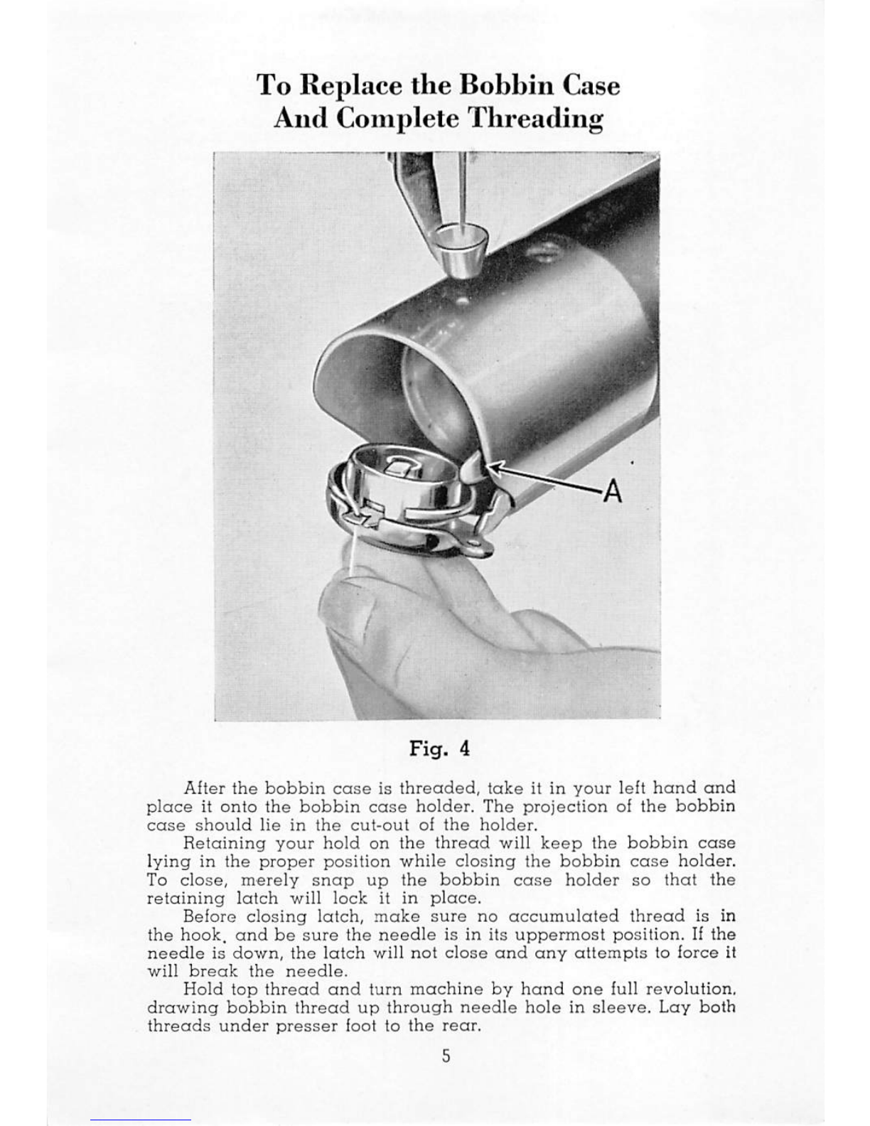
To Replace
the
Bobbin
Case
And
Complete
Threading
Fig.
4
After
the
bobbin
case
is
threaded,
take
it in
your
left
hand
and
place
it
onto
the
bobbin
case
holder.
The
projection
of
the
bobbin
case
should
lie
in
the
cut-out
of
the
holder.
Retaining
your
hold
on
the
thread
will
keep
the
bobbin
case
lying
in
the
proper
position
while
closing
the
bobbin
case
holder.
To
close,
merely
snap
up
the
bobbin
case
holder
so
that
the
retaining
latch
will
lock
it in
place.
Before
closing
latch,
make
sure
no
accumulated
thread
is
in
the
hook,
and
be
sure
the
needle
is in its
uppermost
position.
If
the
needle
is
down,
the
latch
will
not
close
and any
attempts
to
force
it
will
break
the
needle.
Hold
top
thread
and
turn
machine
by
hand
one
full
revolution,
drawing
bobbin
thread
up
through
needle
hole
in
sleeve.
Lay
both
threads
under
presser
foot to
the
rear.
From the library of: Superior Sewing Machine & Supply LLC

To
Begin
Mending
With
the
machine
properly
threaded,
you
are
now
ready
to
begin
mending.
A
few
pieces
of
scrap
material
should
be
used
to
become
accustomed
to
the
feel
of
the
machine.
Lift
up
the
presser
foot
by
means
of
the
hand
lifter
"W"
(Fig. 8)
and
insert
the
material
to
be
darned
beneath
the
presser
foot.
Then
release
the
hand
lifter
to
lower
the
presser
foot
in
operating
position.
A
slight
pressure
to
the
knee
or foot
rheostat
will
start
the
machine.
Fig.
5
The
correct
method
of
holding
the
material
is
shown
above.
The
fingers
should
be
held
as
close
to
the
presser
foot
as
the
hole
to
be
mended
will
allow.
This
method
of
holding
prevents
the
material
from
wrinkling
and
allows
better
control
of
the
cloth.
Now
oscillate
the
material,
first
forward
and
back
and
to
finish,
from
side
to
side.
After
the
mend
is
completed,
lift
up
the
presser
foot,
turn
the
hand
wheel
toward
you
until
the
needle
clears
the
material.
Draw
the
material
out
and
break
off
the
threads.
From the library of: Superior Sewing Machine & Supply LLC
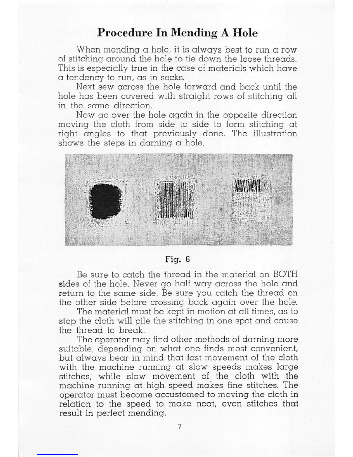
Procedure
In
Mending
A
Hole
When
mending
a
hole,
it is
always
best
to
run
a
row
of
stitching
around
the
hole
to
tie
down
the
loose
threads.
This
is
especially
true
in
the
case
of
materials
which
hove
a
tendency
to
run,
as
in
socks.
Next
sew
across
the
hole
forward
and
back
until
the
hole
has
been
covered
with
straight
rows
of
stitching
all
in
the
same
direction.
Now
go
over
the
hole
again
in
the
opposite
direction
moving
the
cloth
from
side
to
side
to
form
stitching
at
right
angles
to
that
previously
done.
The
illustration
shows
the
steps
in
darning
a
hole.
f'y
I
^ y 'jr
Jil
1 • - ' » £ yj
Fig.
6
Be
sure
to
catch
the
thread
in
the
material
on
BOTH
sides
of
the
hole.
Never
go
half
way
across
the
hole
and
return
to
the
same
side.
Be
sure
you
catch
the
thread
on
the
other
side
before
crossing
back
again
over
the
hole.
The
material
must
be
kept
in
motion
at
all
times,
as
to
stop
the
cloth
will
pile
the
stitching
in
one
spot
and
cause
the
thread
to
break.
The
operator
may
find
other
methods
of
darning
more
suitable,
depending
on
what
one
finds
most
convenient,
but
always
bear
in
mind
that
fast
movement
of
the
cloth
with
the
machine
running
at
slow
speeds
makes
large
stitches,
while
slow
movement
of
the
cloth
with
the
machine
running
at
high
speed
makes
fine
stitches.
The
operator
must
become
accustomed
to
moving
the
cloth
in
relation
to
the
speed
to
make
neat,
even
stitches
that
result
in
perfect
mending.
From the library of: Superior Sewing Machine & Supply LLC
Some
holes
may
be
too
large
for
darning
with
thread
alone.
In
this
case
mend
by
patching,
darning
around
the
patch
after
trimming
stray
threads
or
folding
back
the
edges
to
the
underside.
Then
trim off
the
corners
of
the
patch
on
the
underside
of
the
material.
Use
of
the
Flat
Work
Plate
When
there
is a
great
deal
of
flat
work
to
be
mended,
you
will
find
the
Chandler
Flat
Work
Plate
of
real
value.
(Page
19). To install this
plate
simply
lift
up
the
presser
foot. Be
sure
the
needle
is
at
its
highest
point
and
slide
the
plate
on
to
the
sleeve
of
this
machine.
The
sleeve
will fit in the cut-out in the plate. Then tighten
the
clamp-
screw
at
the
bottom
of
the
yoke,
and
the
plate
is
set
for
sewing.
This
plate
will
be
found
to
be
a
great
help
where
a
larger
surface
is
needed
than
provided
by
the
sleeve
of the machine. Some operators
use
the plate in mending
with
patches,
as
the
extra
surface
allows
free
and
con
venient
handling
of
the
patch
under
the
article
to
be
mended.
To
Regulate
the
Tensions
The
small
thumb
nut
in
front
of
the
tension
discs
A
(Fig. I
6c
2) is for
regulating
the
top
thread
tension. To
tighten
the
top
thread
tension,
turn
this
nut
clockwise
and
to
loosen
the
tension
turn
counter
clockwise.
The tension on
the
bobbin
thread
is
regulated
by
the
small
spring
tension
screw
A (Fig. 3)
located
in
the
center
of
the
bobbin
case
thread
tension
spring
C (Fig. 3),
Take
the
small
screw
driver
furnished
with
the
ac
cessories
and
turn
this
screw
to
the
left
to
loosen
the
bob
bin
thread
tension
and
to
the
right
to
increase
the
tension.
The
correct
tension
on
the
bobbin
thread
is
deter
mined
by
hanging
the
bobbin
case
by
the
thread.
If
the
tension
is
too
loose,
the
bobbin
case
will
slide
down
the
thread.
The
correct
tension
is
one
which
will
allow
the
bobbin
to
be
shaken
down
the
thread.
If
the
bobbin
can
not
be
shaken down the thread, the tension is too tight.
The
usual
procedure
is to
set
the
bobbin
tension
first
and
then
the
top
thread
tension
is
adjusted
until
the
stitch
on
the
under
side
of
the
material
is perfect
and
no
loops
are
formed
as
decribed in the following
paragraphs.
From the library of: Superior Sewing Machine & Supply LLC

Tensions
Perfect stitching depends to a great extent on the
proper adjustment of the
thread
tensions. The machine,
as
it comes to you,
has
the tensions properly adjusted,
but you
will
need to readjustthem
frequently,
depending
on
type
of
material
sewed
and
thickness
of
thread
used.
If
the
stitching is
correctly
done
and
the
tensions
are
properly
adjusted,
the
threads
should
meet
in
the
center
of the material,
as
shown
by
A (Fig.7).
B
3000L
Fig.
7
If
the
top
thread
is
too
tight
or
the
bobbin
tension
is
too loose,
the
bottom
thread
will
be
pulled
to
the
top
of
the
material
as
illustrated
in
C(Fig.7).
When
the
top
thread
is
too
loose
or
the
bobbin
thread
is too tight, the
bobbin
thread
will lie
along
the
under
side
of
the
material
as
shown
in
B(Fig.7),
or
it will
form loops.
When
the top
thread
is too loose,
causing
these
loops to
appear,
the
darning
will
appear
to
be
bunchy
and
will
not
give
the
appearance
of a
neat
job.
From the library of: Superior Sewing Machine & Supply LLC

Presser
Foot
Adjustiiieiit
The
knob
F (Fig. 8) is
an
adjustment
built into the
machine
to
enable
it to
work
on
the
heaviest
as
well
as
the
lightest
materials
by
making
only
the
simplest
oi
adjustments.
The
machine,
as
it
comes
to
you,
is
adjusted
ior
light
and
medium
work.
When
such
heavy
work
as
nets,
coats,
blankets,
over-alls,
and
aprons
is
encountered,
raise
the
presser
loot
by
means
of
the
hand
lifter
W
and
take
hold
of
the
adjusting
knob
F
(Fig.
8),
Pull
this
knob
out
and
turn
a
half
turn
toward
you;
the
adjustment
knob
will
then
slip
into
its
new
position.
On
returning
to
light
work,
this
adjustment
must
be
returned
to
its
original
position.
V LF
Fig.
8
From the library of: Superior Sewing Machine & Supply LLC
Motor
Belt
Adjustment
In
order
to
get
the
maximum
speed
and
power
from
the
motor,
it is
essential
that
the
motor
belt
is
correctly
adjusted.
If
the
belt
is
too
tight,
it will
cause
unnecessary
wear
of
the
bearings,
belt,
and
motor
shaft
and
also
slow
down
the
machine.
If
the
belt
is
too
loose,
the
belt
will
slip
and
fail to
bring
the
machine
up
to
speed.
The
tension
of
the
belt
may
be
adjusted
by
means
of
the
motor
lock
screw.
Loosen
this
screw
and
bring
the
motor
to
the
position
desired
and
retighten.
It is a
good
policy
to
also
tighten
the
motor
hinge
pin
screw,
as
this
will
give
additional
resistance
to
the
motor
being
pulled
out
of
adjustment.
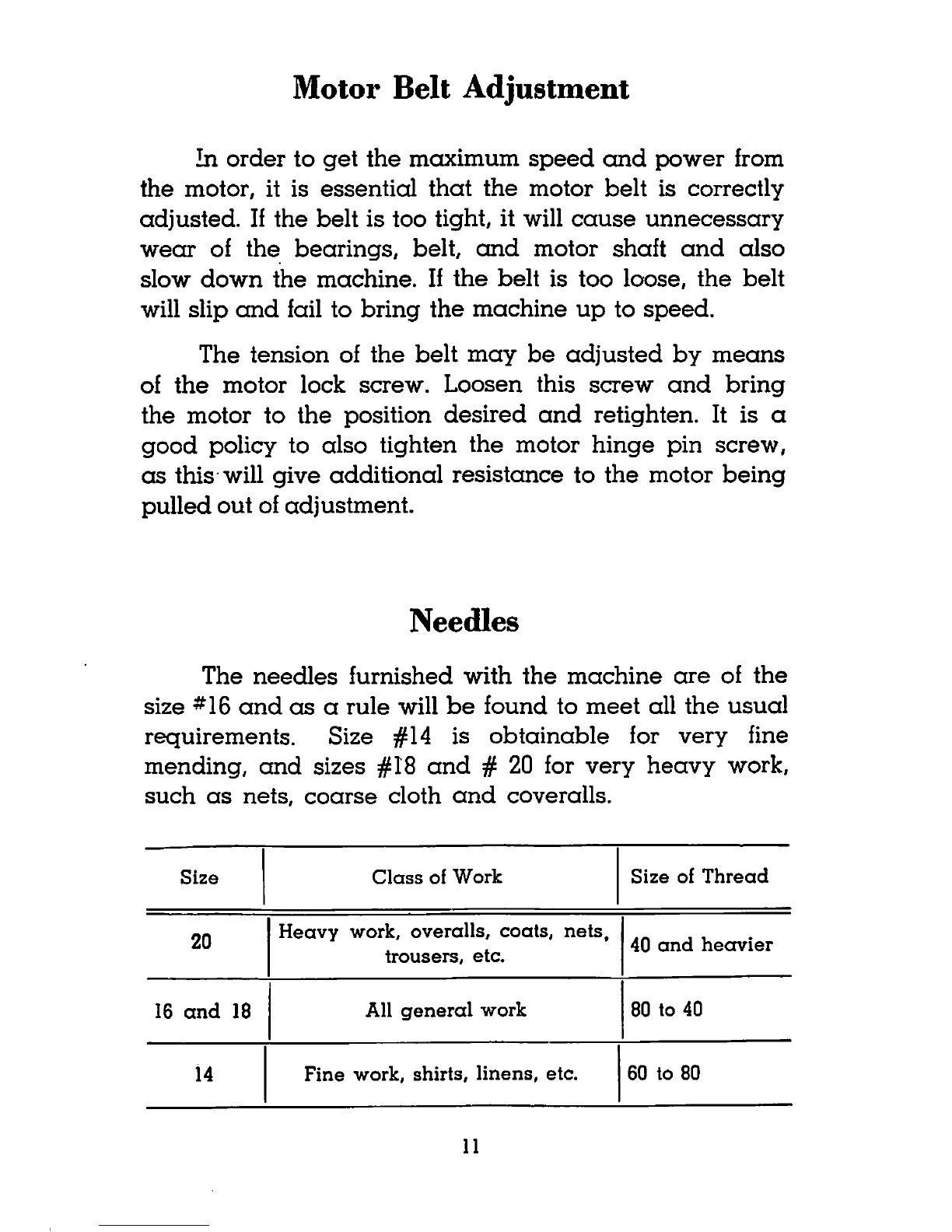
Needles
The
needles
furnished
with
the
machine
are
of
the
size
*16
and
as
a
rule
will
be
found
to
meet
all
the
usual
requirements.
Size
#14 is
obtainable
for
very
fine
mending,
and
sizes #18
and
# 20 for
very
heavy
work,
such
as
nets,
coarse
cloth
and
coveralls.
Size
Class
of
Work
Size
of
Thread
20
Heavy
work,
overalls,
coats,
nets,
trousers,
etc.
40
and
heavier
16
and
18 All
general
work
80
to
40
14
Fine
work,
shirts,
linens,
etc.
60
to
80
11
From the library of: Superior Sewing Machine & Supply LLC

To
Set
the
Needle
Turn
the
hand
wheel
toward
you
until
the
needle
bar
is in
its
uppermost
position.
Then
insert
the
needle
into
the
hole
in
the
needle
bar
with
the
FLAT
SIDE
of
the
shank
toward
the
needle
clamp
screw.
Make
sure
that
the
needle
is
pushed
up
into the hole
as
far
as
it will go.
Now
clamp
the
needle
in
this
position
by
means
of
the
needle
clamp
screw.
Thread
A
good
grade
of
thread
should
be
used
with
the
machine. If the
thread
is
rough
or uneven, or, if it
passes
with difficulty
through
the
eye
of
the
needle,
the
suc
cessful
use
of
the
machine
is
interfered
with.
Left twist
thread
should
always
be
used,
and
the
thread
for
both
the
needle
and
the
bobbin
should
be
of
the
same
size. A 60
(GO)
thread
can
be
used
for
general
purposes.
It
should
be
soft,
mercerized
and
not
contain
any
hard
qualities.
A 40 (0)
thread
is
heavier
and
can
be
used
for
mending
coats,
aprons,
nets
and
other
heavier
materials.
A 40 (0)
thread
should
not
be
used
for socks,
linens, etc.,
as
this
work
requires
the
finer
thread.
See
paragraph
under
"needles."
Oiling
and
Lubrication
To
insure
the
life of the machine, all
parts
which
are
in
movable
contact
with
each
other
should
be
oiled
at
least
once
a
day.
A fine,
light
oil
should
be
used
which
12
From the library of: Superior Sewing Machine & Supply LLC

you
can
obtain
from
the
factory
or
any
authorized
agent.
All oil
holes
are
plcdnly
marked
with
the
exception
of
the
motor
bearings
at
each
end
of
the
motor.
These
bear
ings
should
have
a
few
drops
of oil
occasionally
all
de
pending
on
the
amount
of
use
that
the
machine
has.
Do
not
over-oil
the
motor.
A
drop
of oil
should
be
applied
every
day
to
the
raceway
of
the
hook.
This
prevents
undue
friction
and
also
helps
prevent
upper
thread
breakage.
Once
or
twice
a
month
we
recommend
the
applica
tion of a light
grease
or
gear
lubricant
to
the
two
sets
of
gears
in
the
machine.
The
top
gears
may
be
reached
by
moving
the
nickeled
plate
at
the
top
rear
of
the
machine
to
the
side;
the
bottom
gears
by
removing
the
base
thumb
screw
N
(Fig.l)
and
tilting
the
machine
back.
Do
not
use
a
cheap
oil,
and
also
keep
away
from
heavy
motor
oils,
as
this
gums
the
machine
and
causes
it to
run
slow
and
overstrain
the
motor.
Always
use
a
high
grade
sewing
machine
oil.
To
Oean
the
Hook
and
Bobbin
Unit
At
regular
intervals
it is
necessary
to
clean
out
the
thread
and
lint
which
will
accumulate
in
the
hook
and
bobbin
unit
inside
the
nickeled
sleeve
on
the
mending
arm.
We
recommend
that
this
be
done
at
the
end
of
each
working
week.
Remove
the
retaining
screw
on
the
sleeve
S
(Fig.l)
and
slide
off
the
sleeve
from
the
end
of
the
arm.
Clean
the
unit
of
all
thread
and
lint.
When
replacing
the
sleeve
be
sure
that
the
needle
lines
up
with
the
hole
in
the
sleeve
before
tightening
the
retaining
screw.
To
Qean
Base
Plate
Excess
oil
will
run
from
inside
the
machine
to
the
base.
To
prevent
this
excess
oil from flooding
onto
the
table
and
soiling
goods
to
be
mended,
it is a
good
policy
to
wipe
out
the
base
weekly. To
do
this,
remove
the
thumb
screw
N
(Fig.l)
and
tilt
machine
back.
13
From the library of: Superior Sewing Machine & Supply LLC

Thread
Breakage
Occasionally
some
thread
breakage
might
occur.
In
this
case
check
the
following
for
the
trouble:
1.
Top
thread
tension
too
tight.
2.
Remove
bobbin
and
check
to
see
that
it
has
proper
tension
and
correct
threading,
3.
Wrong
thread.
Either
wrong
twist
or
too
heavy
for
needle
being
used.
4.
Follow
top
thread
back
from
needle
to
see
if it
has
been
double
twisted
around
any
of
the
thread
guides.
5.
Be
sure
no
cord,
box
nor
other
obstruction
is
lean
ing
against
or
is
contacting
thread
cone
causing
undue
and
uneven
thread
release
from
the
cone.
6.
Check
needle
to
see
if it is
properly
placed
in
needle
bar.
Flat
part
of
needle
must
be
to
the
right,
on
the
same
side
as
the
needle
clamp
screw.
7.
Run
finger
nail
along
needle
point
and
check
for
any
small
burr
or
bent
point.
If
burr
is felt,
remove
and
replace
with
new
needle.
8. Do
not
continue
to
sew
in
one
spot;
do
not
let
the
machine
run
any
length
of time
on
the
same
spot
of
material.
9. In
darning
across
a
hole,
be
sure
to
catch
the
thread
on
either
side.
Do
not
darn
half
way
across
and
re
turn
to
the
same
side.
The
loose
loop
of
the
thread
will
be
carried
down
to
the
hook
by
the
needle
and
snap
your
thread.
10. Too violent motion of
the
cloth or
sudden
jerks
of
the
material
will
snap
the
thread
in
the
eye
of
the
needle.
11. Remove
the
nickel-plated
sleeve
and
check point of
hook
to
see
if
needle
has
struck
it
to
cause
a
burr
on
its
point.
Use
a fine
stone
to
remove
any
burr
on
hook
point.
Do
not
use
a file.
Hook
should
not
be
removed
nor
loosened
unless
point
is
actually
broken
off,
14
From the library of: Superior Sewing Machine & Supply LLC
INSTRUCTIONS
for
TIMING,
ADJUSTING,
AND
CHECKING
THE
MECHANICAL
SETTINGS.
All
mechanical
settings
should
be
left
strictly
alone,
and
should
not
be
tampered
with.
The
following
pages
are
only
for
those
who
must
replace
essential
parts
or
for
those
who
have
experienced
trouble
in
operating
their
machines
and
wish
to
double
check
on
the
mechanical
settings
to
see
if
the
machines
are
properly
adjusted.
Important
replaceable
Parts
illustrated
at
the
end
of
these
instructions
15
From the library of: Superior Sewing Machine & Supply LLC
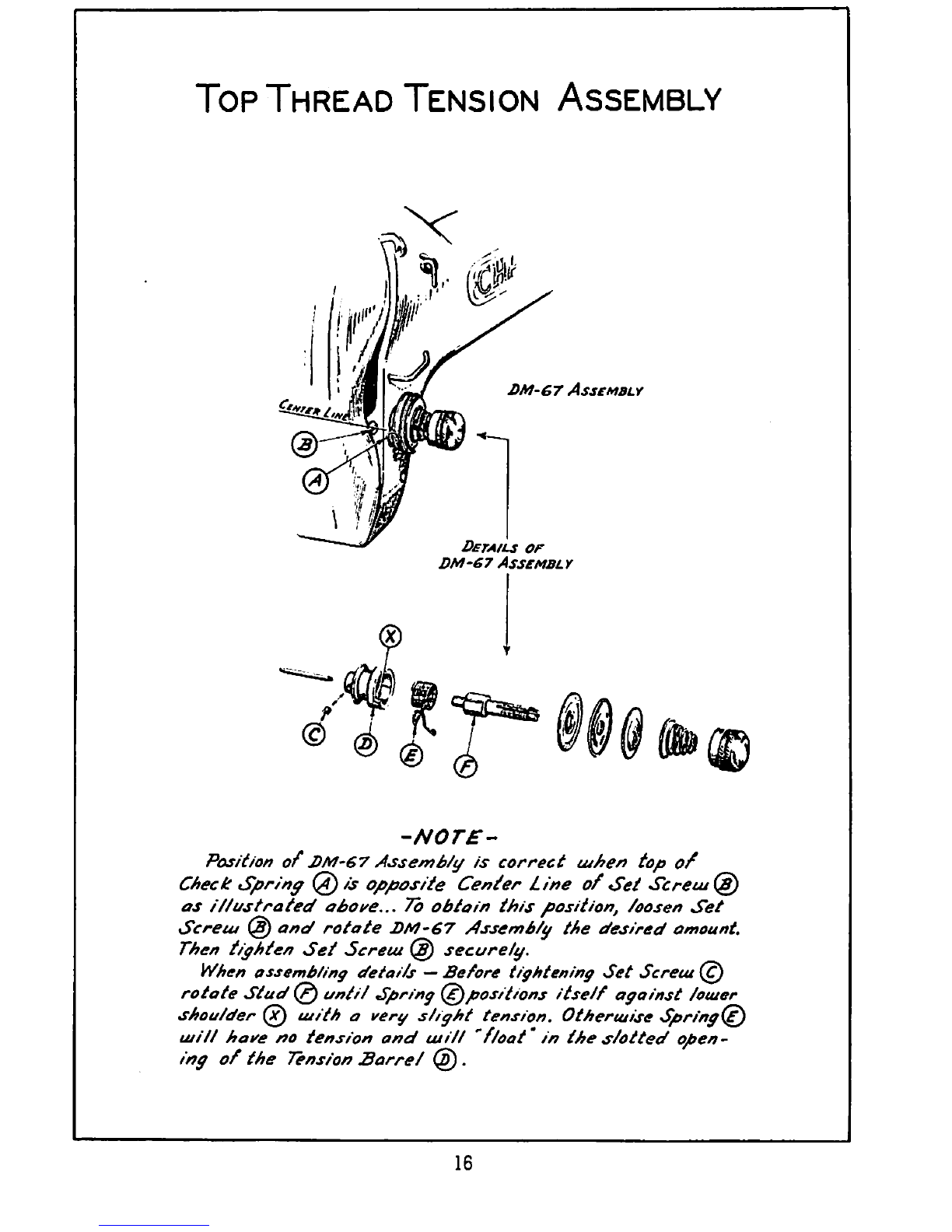
Top
Thread
Tension
Assembly
DM-67
Assembly
Details
of
DM-67
Assembly
-NOTE-
Position
of
J)M-67
Assembit/ is correct tuben top
of
Check
Sprinff@ is opposite Center Line of Set
Screuit^
as
il/ustrated
obore...
To
obtain
this
position,
Loosen
Set
Screu! @ and rotate
DM-67
Assemb/y
the desired
amount.
Then
tiyhten
Set
Screm @ securely.
When ossemb/iny
details
—Before tiyhteniny
Set
Screut
rotate
Stud^)
until
Spriny
(^positions itself ayainst
lotuer
shoulder ujith a very sliyht tension. Otherujise Spriny(^
ujill have no tension
and
us
ill
'float' in the
s/otted
open
ing of the
Tension
Barrel
@ .
16
From the library of: Superior Sewing Machine & Supply LLC
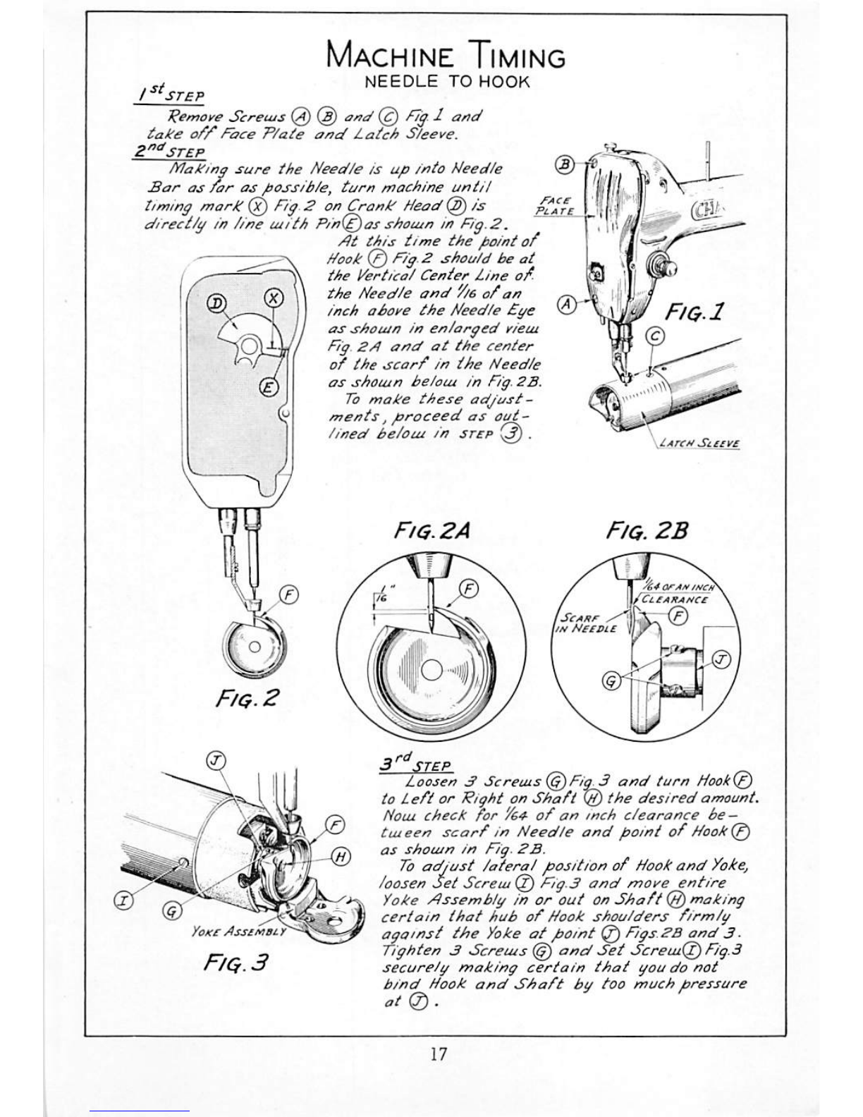
Machine
Timing
-y
NEEDLE
TO HOOK
/
"sr£P
'Remoye
Sereuis(2)@
take
o/y
Face
P/ate
and
Latch
S/eeve.
Z"^3TEP
Making
sure
the
Need/e
is
up
into
Needle
Sar
as
far
as
possib/e,
turn
machine
until
timing
mark ©
Fig.
2 onCrank Head©
/is-
^
direct/gintineuiith Pin(^as
shouin
inFig.2.
Ht this time the point
of
Hook
©
Fig.
2 shou/dbeat
j
^^
the
lierticai
Center
Line
of.
\f
iTi\
W
Needle
and
'f/e
of
an
\
aboye
the
Needle
£ye
' L r\ //
shouin
in enlarged
yiem
I Nig.
ZH
and
at
the
center
j of the
scarf
in the
Needle
gA as shouin beloin in
Fig.
2B.
J
To
make these
adjust-
(y
ments,
proceed
as
aut--
\ 1
lined
be/oui in
step
.
Fig.
2A
Fig.2
d'l
P 4
.lArcM
Sceiye
Fig.
2B
ISeAEr
^
lin
NecBiE
ii4arAiiiiiici!s
TCliahaucs
•3k
0 _
Yokc
PssenOLy
Fig.
3
Loosen
dScreuist^Fig^ and turn
Hook(^
to L
eft
or Right on
Shaft
@
the
desired
amount.
Noui
check
for
Yes
of
an
mch
clearance
be
—
tuteen
scarf
in Needle
and
point
of
Nook
as
shouin
in
Fig.
2B.
To
adjust
lateral
position of
Hook
and
Yokej
loosenSet Screui@ Fig.3
and
more entire
Yoke
Assembly in or out on
Shaft
@ making
certain
that
hub
of
Hook
shoulders
firmly
(^omst the
Yoke
at
point @
Figs.kB
and
3•
Tighten3 Screuis ©
and
Set
ScreuiQ)
Fig.3
securely
making
certain
thai
you
do
not
bind
Hook
and
Shaft
bu
too
much
pressure
atO).
From the library of: Superior Sewing Machine & Supply LLC
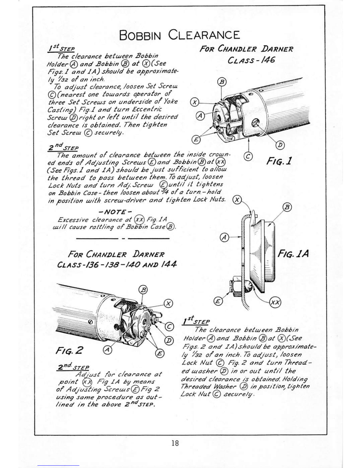
Bobbin
Clearance
I^^STCP
The
clearance
betiueen
Sobb/n
Holder!^
and
£obbin
@ at (^(See
F'iffs.
I
and
JA) should be approximate
ly
'/az
ofan
inch.
To
adjust
c/earance,
Joosen
Set
Screiu
(^(nearest
one
toujords operator of
three
Set
Screius on underside
of
Yoke
Castiny) F7y.l
and
turn
Eccentric
Screu!@ rightor /eft until the desired
c/earonce
is
obtained.
Then
tighten
Set
Screui@ securely.
For
Chanbler
Darner
Class
-
/46
Si
j/cr
The
amount
of
clearance
between
the
inside
crown
ed
ends
of
Adjusting
Sereuis(^and £obbin^)at(x^
(SeeF/gs.J
and
JA) shouldbeJust sufficient to
alloia
the
thread
to
pass
between
them.
7b
adjust, loosen
Lock
liutsand turn
Adj.
Screw
(^untHit
tightens
on Bobbin Case -
then
loosen
about
W
of
a
turn.
-
hold
in
position
with screwdriver
and
tighten
Lock
Huts.
-NOTE-
Excessive
clearance
at
(xi^
Tig.
JA
will
Cause
rattling of
BoMin
Case(^.
For
Chanbler
Darner
Ciass-/36-I3S-I40
AND
144-
Fiq.1
Fig.
JA
Fig.
2
STEP
Adjust
for
clearance
at
point
F'ig
IA
by
means
of Adjusting Screuis(^Fig 2
using
same
procedure
as
out
lined
in
the
above
B^^STSP.
/
STEP
The
clearance
between
Bobbin
Holderf^and Bobbin
@at
@(See
F'gs
2
and
IA)shauldbe
app/vximafe'
Ig '/as
of
an inch. 7b
adjust,
loosen
L
ock
Nut @
Fig.
2
and
turn
Thread-
ed
washer
@ in or out
until
the
desired
clearance
is
obtained.
Holding
Threaded
Washer
@ in
position^
tighten
Lock
Hut
secure/g.
From the library of: Superior Sewing Machine & Supply LLC
Table of contents
Other Chandler Sewing Machine manuals


