Chandler AMETEK 5617 User manual

INSTRUCTION MANUAL
MODEL 5617
CORROSION TEST APPARATUS
Revision T –June 2021
P/N: 56-170-10-15
S/N: ____________
2001 N. Indianwood Ave. Broken Arrow, OK 74012
Telephone: 918-250-7200
Fax: 918-459-0165
E-mail: chandler.sales@ametek.com
Website: http://www.chandlereng.com

Copyright 2014, by Chandler Engineering Company L.L.C.
All rights reserved. Reproduction or use of contents in any manner is prohibited without express permission from Chandler Engineering Company L.L.C.
While every precaution has been taken in the preparation of this manual, the publisher assumes no responsibility for errors or omissions. Neither is any
liability assumed for damages resulting from the use of the information contained herein.
This publication contains the following trademarks and/or registered trademarks: AMETEK, CHANDLER ENGINEERING. These trademarks or registered
trademarks and stylized logos are all owned by AMETEK, Inc. All other company, product and service names and logos are trademarks or service marks of
their respective owners.


TABLE OF CONTENTS T-1
Table of Contents
General Information ....................................................................... P-1
Introduction........................................................................................................................................P-1
Purpose and Use...........................................................................................................................P-1
Description...................................................................................................................................P-1
Features and Benefits.........................................................................................................................P-1
Specifications.....................................................................................................................................P-2
Safety Requirements..........................................................................................................................P-3
Where to Find Help............................................................................................................................P-3
Section 1 –Installation....................................................................1-1
Unpacking the Instrument..................................................................................................................1-1
Utilities Required............................................................................................................................... 1-1
Tools/Equipment Required................................................................................................................1-1
Setting Up the Instrument..................................................................................................................1-1
System Set-up ....................................................................................................................................1-2
Remote Panel Connection............................................................................................................1-2
Section 2 –Operating Instructions...................................................2-1
Main Control Panel............................................................................................................................2-1
Remote Control Panel........................................................................................................................2-2
Sample Preparation............................................................................................................................2-3
Pressurizing the Cylinder...................................................................................................................2-3
Heating the Cylinder..........................................................................................................................2-4
Manual Controller Operation.......................................................................................................2-4
Sample Rack Reciprocation...............................................................................................................2-4
Cooling the Cylinder..........................................................................................................................2-5
Emptying the Cylinder.......................................................................................................................2-5
Water Flushing the Cylinder..............................................................................................................2-6
Section 3 –Maintenance..................................................................3-1
Chillers...............................................................................................................................................3-1
Tools Required...................................................................................................................................3-1
After Every Test................................................................................................................................. 3-1
Pressure Cylinder......................................................................................................................... 3-1
Sample Rack ................................................................................................................................ 3-2
Centerline Thermocouple............................................................................................................. 3-2
Monthly..............................................................................................................................................3-2
Drive Motor System..................................................................................................................... 3-2
Hydraulic Pump........................................................................................................................... 3-2
Thermocouple and Temperature Control System........................................................................3-2
Packing Cartridge.........................................................................................................................3-2
Three Months.....................................................................................................................................3-3
Oil Filter.......................................................................................................................................3-3
Six Months.........................................................................................................................................3-3
Air Operated Valve......................................................................................................................3-3

T-2 TABLE OF CONTENTS
Annually............................................................................................................................................. 3-3
Pump............................................................................................................................................3-3
Heater...........................................................................................................................................3-3
Thermocouple and Temperature Controller.................................................................................3-3
Maintenance Schedule....................................................................................................................... 3-4
Section 4 –Troubleshooting Guide.................................................4-1
Section 5 - Replacement Parts.........................................................5-1
Section 6 - Drawings and Schematics..............................................6-1
Includes:
2408i Universal Indicator and Alarm Unit

PREFACE P-1
General Information
Introduction
Purpose andUse
The corrosion test apparatus was designed to test the reaction rate of corrosive liquids on
metals that are subjected to high temperature and pressure under dynamic conditions in
compliance with ASTM G111. The corrosive liquid and the metal coupons are placed in
glass jars that are placed in a metal rack. This rack is inserted into the pressure chamber, the
chamber is filled with oil, and the rack is agitated during the temperature-pressure cycle. The
agitation rate is adjustable. See Sample Rack Reciprocation in Section 2 -Operation.
Description
The pressure vessel is an alloy steel cylinder approximately 11 inches / 28 cm in diameter
with a threaded plug for closure.
Heat is applied using three external heaters with 9,000 Watt (VA) capacity. They generate a
maximum rate of temperature rise of 7F per minute. Internal and external cooling coils
provide cylinder cooling.
The pressure chamber with the heating jacket is mounted in a stainless steel cabinet that
contains all the necessary piping and controls. The motor used to agitate the samples and
pump rated for 10,000 psi / 69 MPa are also located in the cabinet. The system is fully
equipped with safety equipment including an over-temperature protection, a pressure rupture
disc, and pressure alarm relays.
Optionally, the Model 5270 Data Acquisition and Control System (DACS) can be used to
acquire and plot temperature and pressure data as a function of time. The software option
requires a computer and data acquisition hardware located within the instrument.
Features and Benefits
•Designed for safe operation including both over-temperature and over-pressure
protection.
•Operating pressure to 10,000 psi / 69 MPa.
•Operating temperature to 500oF / 260oC.
•Sample rack can be agitated during testing with 3 different agitation angles and 3
different agitation rates.
•Remote control operation allowing the user to control both temperature and pressure at a
distance of up to 50 feet from the instrument.
P-2 PREFACE
Specifications
Operating Conditions: 75°F - 500°F / 23°C - 260°C
Maximum Temperature: 500°F / 260°C
Maximum Pressure: 10,000 psi / 69 MPa
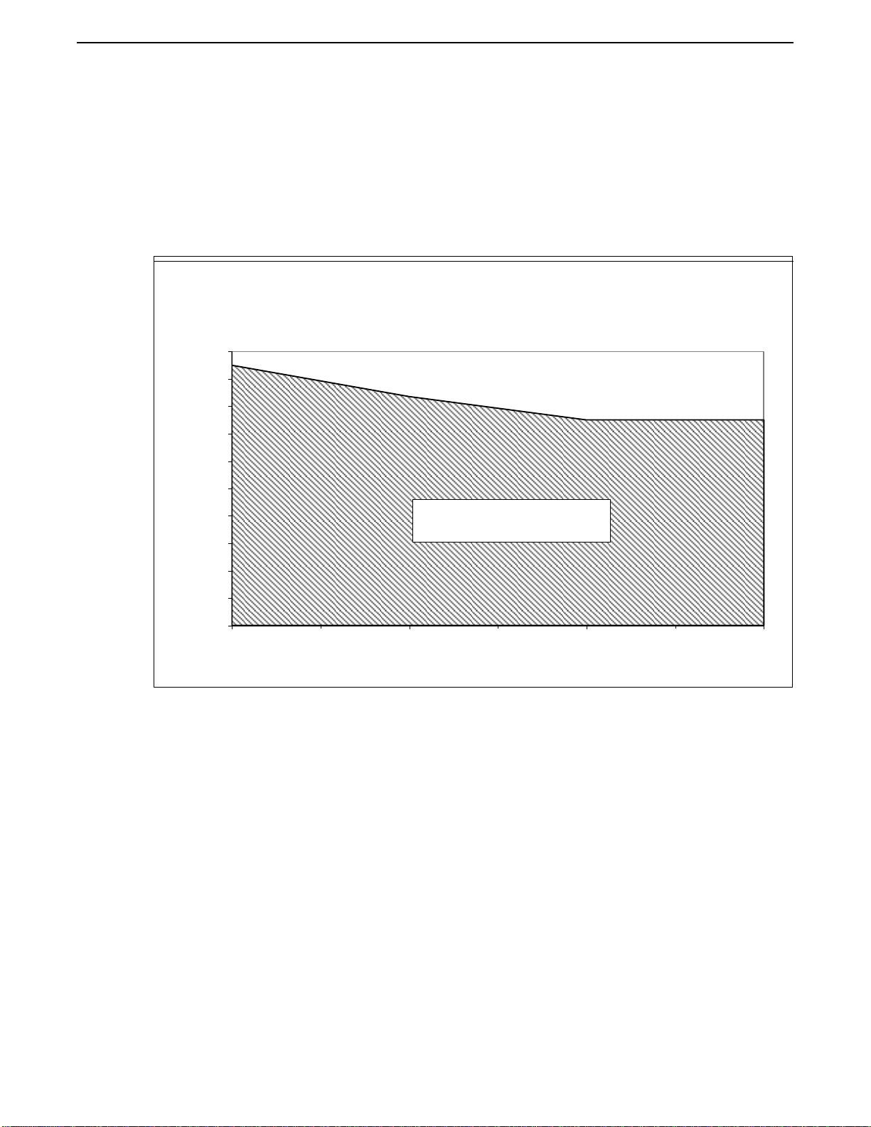
Note: The pressure rating decreases as the temperature increases (see chart below).
Model 5617 Corrosion Test Apparatus
Pressure Rating Schedule
0
1000
2000
3000
4000
5000
6000
7000
8000
9000
10000
75 200 400 500
Temperature, Deg. F
Pressure, psig
Safe Usage Area
Input Voltage: 230 VAC ± 15%; 50/60 Hz ± 10%
Input Power: 10 KVA
Heater Wattage: 9000 Watts
Dimensions: 67 in. / 170 cm high x 39 in. / 99 cm wide x 33 in. / 84
cm deep
Net Weight: 2200 lbs / 998 kg
Specimen Capacity: 20 –4 fl. oz. sample bottles (or)
8 –8 fl. oz. sample bottles
Agitation Angles: 40o, 60o, or 80o
Agitation Rate: 35, 60, or 100 cycles/minute
Maximum Temperature Rise: 2oC/minute

PREFACE P-3
Safety Requirements
READ BEFORE ATTEMPTING OPERATION OF INSTRUMENT
The Chandler Engineering Model 5617 Corrosion Test Apparatus is designed for operator
safety. Any instrument that is capable of high temperatures and pressures should always be
operated with CAUTION!!
To ensure safety:
•Locate the instrument in a low traffic area.
•Post signs where the instrument is being operated to warn non-operating personnel.
•Read and understand instructions before attempting instrument operation.
•Observe caution notes!
•Observe and follow the warning labels on the instrument.
•Never exceed the instrument maximum temperature and pressure ratings.
•Always disconnect main power to the instrument before attempting any repair.
•Turn off the heater at completion of each test.
•Appropriately rated fire extinguishers should be located within close proximity.
•Note that the flash point of the mineral oil used in this instrument is less than the
maximum operating temperature of the instrument. The auto ignition temperature of the
mineral oil is at or above the maximum operating temperature. When operating the
instrument at the maximum operating temperature, take appropriate steps to minimize the
chance of fire if a leak should develop.
Where to Find Help
In the event of problems, contact your local sales representative or Chandler Engineering:
•Telephone: 918-250-7200
•Fax: 918-459-0165
•E-mail: [email protected]
•Website: www.chandlereng.com
Instrument training classes are also available.

P-4 PREFACE
This page is intentionally left blank.

SECTION 1 –INSTALLATION 1-1
Section 1 –Installation
Unpacking the Instrument
Remove the instrument from the packing crate carefully. The unit comes fully equipped with
all the necessary components and ordered spare parts. Make sure that no parts are lost when
discarding the packing materials. Place the instrument on a firm table, close to the water
source and required electrical outlets.
After the instrument is removed from the shipping crate, the equipment and spare parts
should be checked against the packing list to ensure that all parts have been received and
none are damaged.
Note: File an insurance claim with your freight carrier if damage has occurred
during shipping. Verify all parts shown on the enclosed packing list have
been received. If items are missing, please notify Chandler Engineering
immediately.
Utilities Required
Your unit will require dry, oil-free compressed shop air (not instrument quality) of 100 to
130 psi / 689 –896 kPa, and a water supply of 20 to 80 psi / 138 –552 kPa. The unit is
capable of operating in ambient temperatures from 50°F to 120°F / 10°C - 49°C.
Tools/Equipment Required
An English unit mechanics tool set is adequate for the installation, operation, and
maintenance of the instrument. No special tools are required.
This unit is supplied with an accessory kit, which includes the necessary hardware for the
water, air, and electrical hook-ups. The water and air hose may be cut to length and the
appropriate barbed fittings inserted into the hose and clamped into place.
Caution: The laboratory electrical power wiring must be capable of a 45-ampere
load and comply with local electrical codes. The instrument must be
securely connected to an appropriate earth ground. The ground wire must
have a larger diameter than that of the supply voltage conductors.
Setting up the Instrument
The air, drain, and water connections are made at the lower rear of the instrument. The inlets
are 1/4in. female pipe thread. The installation kit, provided with the instrument, contains the
necessary hose and fittings to make the connections. Electrical connections are made using
the 50-ampere rated connector and power cord provided with the instrument. Be certain that
all power wiring is rated for the 45-ampere load. The wiring must be installed in accordance
with local electrical codes, and the entire instrument must be securely connected to a separate
ground.

1-2 SECTION 1 –INSTALLATION
System Set-up
RemotePanelConnection
1. The remote panel assembly is connected to the instrument by connecting the
thermocouple cable from the remote panel assembly to the labeled receptacle on the back
of the instrument. The signal cable is also connected to a labeled receptacle at the back
of the instrument.
2. If the system is equipped with the Chandler Engineering 5270 Data Acquisition and
Control System (DACS) software, the RS232 cable is connected to a serial port on the
computer.
3. Turn ON all equipment.
56-0302
Signal Cable
56-0303
Thermocouple Cable
RS232 Cable
MODEL5617
SECTION 2 –OPERATING INSTRUCTIONS 2-1
Section 2 –Operating Instructions
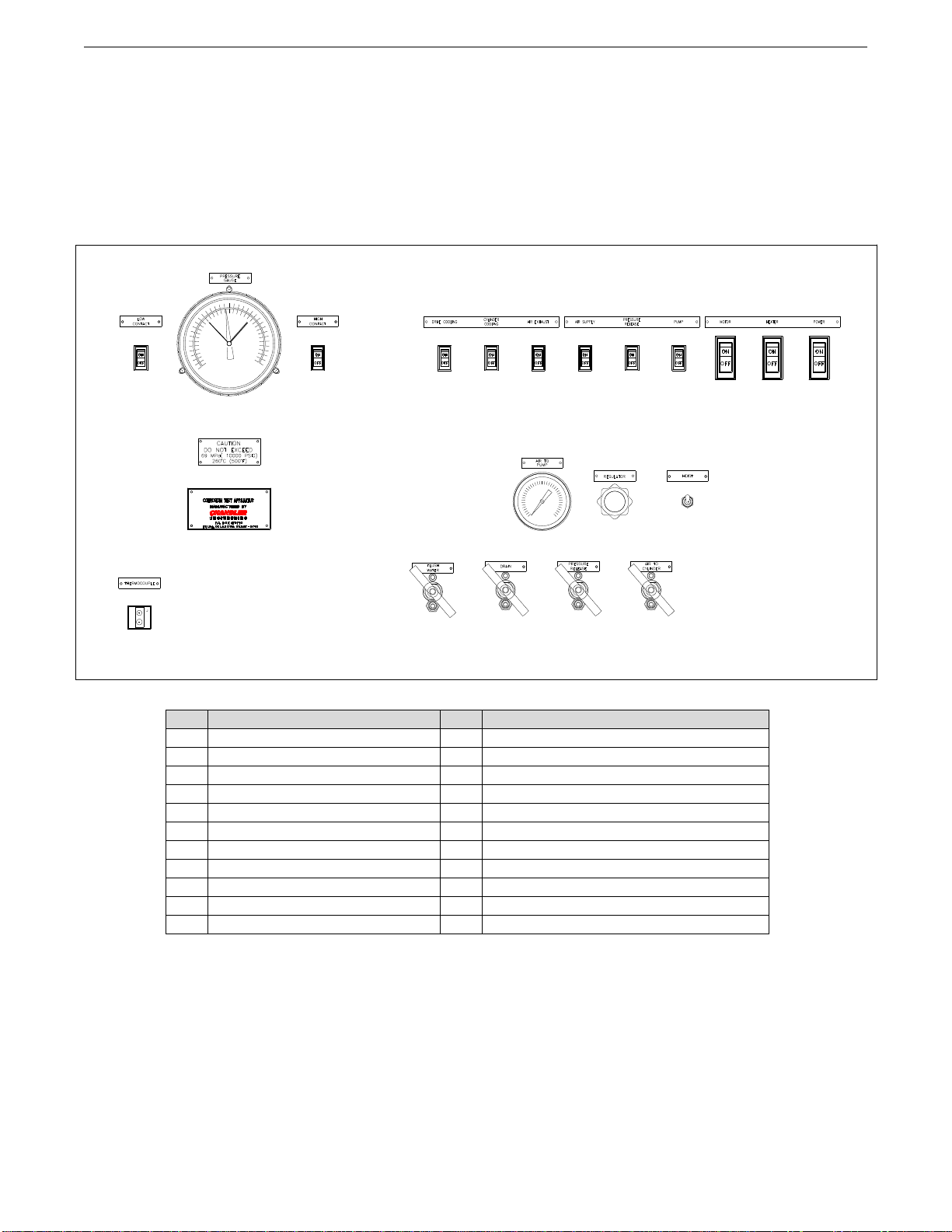
Main Control Panel
ID
Description
ID
Description
1
Thermocouple Receptacle
12
Pump Switch
2
Nameplate
13
Motor Switch
3
Caution
14
Heater Switch
4
Low Pressure Contact
15
Main Power
5
Pressure Gauge
16
Pressure and Temperature Rating
6
High Pressure Contact
17
Air Pressure Regulator
7
Drive Cooling Switch
18
Hoist Switch
8
Cylinder Cooling Switch
19
Flush Water Valve
9
Air Exhaust Switch
20
Drain Valve
10
Air Supply Switch
21
Pressure Release Valve
11
Pressure Release Switch
22
Air-to-Cylinder Valve
119
MODEL 5617
2
4
3
6 7
5
17
20 21 22
16
8 9 10
13
11 12
14 15
18
2-2 SECTION 2 –OPERATING INSTRUCTIONS
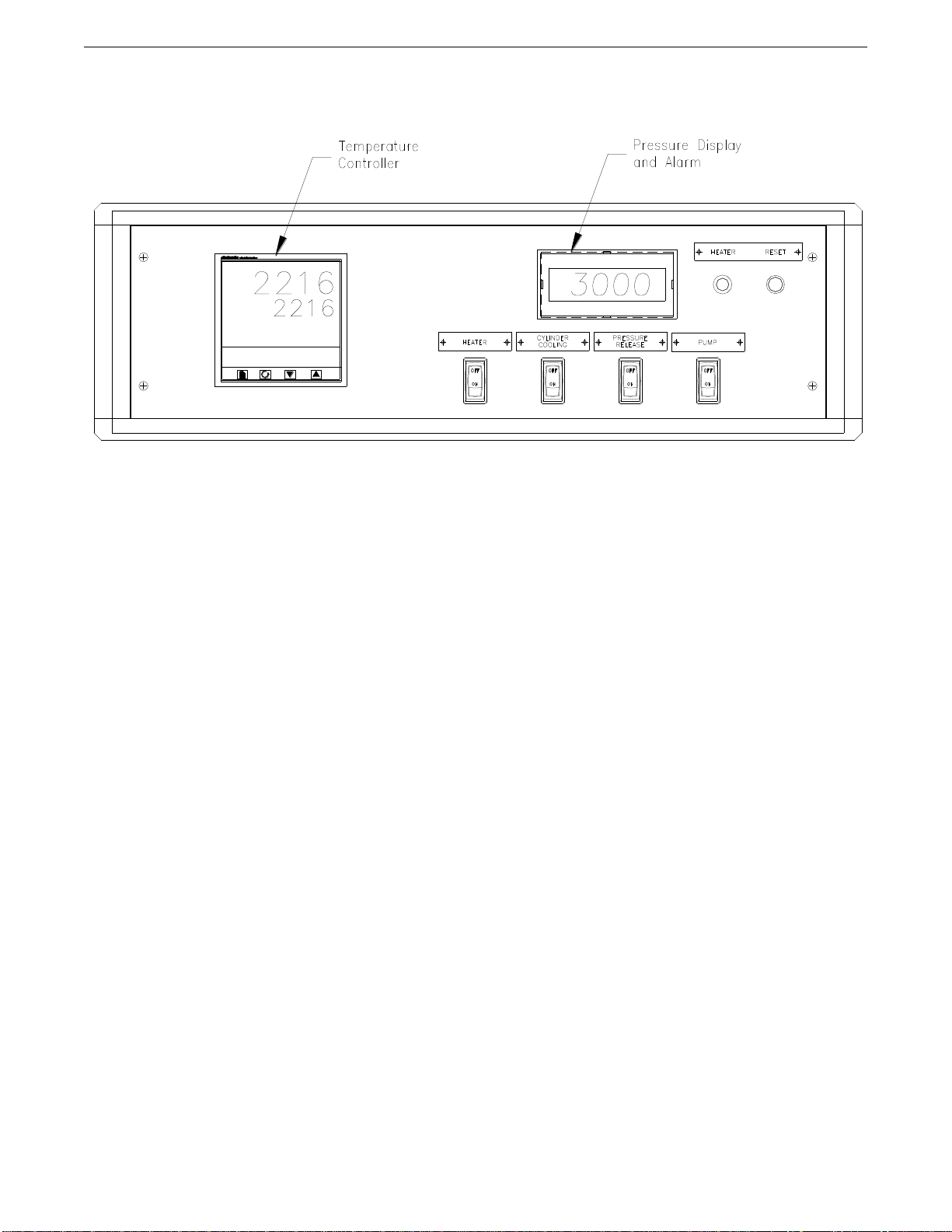
Remote Control Panel
This instrument is furnished with a remote control panel, which permits operation of the
instrument from a remote location. The remote panel assembly and the instrument may be
separated up to 50 feet.
From the remote panel, the operator may control the following items:
•Control temperature using the programmable temperature controller.
•Read the pressure on the digital display.
•Control the pressure using the PUMP and PRESSURE RELEASE switches.
•Turn the heater “ON” or “OFF” using the HEATER SWITCH.
•Turn the cooling water to the cylinder jackets “ON” or “OFF” using the COOLING
WATER SWITCH.
•When the option exists, the remote control assembly is connected to the computer
running the 5270 DACS software. The values displayed on the temperature controller
and pressure display are graphed and stored in the test data file.
Note: The cylinder pressure can be automatically controlled by setting the high and
low contacts of the pressure control gauge on the instrument panel to the
desired pressure range. (Position switch #4 or #6 to “ON” to activate the
LOW or HIGH pressure limit.) Pressure may still be controlled with the
remote switches.

SECTION 2 –OPERATING INSTRUCTIONS 2-3
Sample Preparation
Generally, individual samples are placed inside each sample container and half filled with the
corrosive media. The remaining internal volume is filled with mineral oil. To prevent
rupturing the sample containers during pressure equalization, the caps must be loose.
Optionally, a 1/8-inch / 4mm hole may be drilled in the cap of each sample container to
provide a path for pressure equalization.
Caution: The height of the 8- container rack prevents safe removal without first
draining the oil from the vessel. Use caution to avoid burns when removing
this rack.
Rapid changes in the cylinder pressure must be avoided to prevent damage to the sample
containers and increased contamination of the mineral oil. Since contamination of the
mineral oil with acids is likely during a normal test, the oil in the cylinder must be replaced
after each test to prevent corrosive attack of the cylinder and related components.
Pressurizing the Cylinder
1. Close all the valves.
2. Turn the switches on the remote panel to “OFF.”
3. Fill the reservoir with mineral oil, if required.
4. With the cylinder to plug removed, turn “ON” the AIR SUPPLY SWITCH (#10) to
partially fill the cylinder. Note that the sample racks displace considerable volume and
must be taken into account when filling the cylinder.
5. Turn “OFF” the AIR SUPPLY SWITCH when the cylinder is approximately 1/2 full and
turn “ON” the AIR EXHAUST VALVE SWITCH (#9).
6. The cylinder may be pre-heated at this point using the temperature controller. The rack
must be placed in the cylinder to agitate the oil during the heating. Turn “ON” the
MOTOR switch (#13) to agitate the rack.
7. If required, lubricate the cylinder plug threads and seal ring with high-temperature grease.
This will allow the plug to be removed after the test is complete.
Caution: The cylinder and rack may become extremely HOT. Severe burns can
result from touching.
8. After lowering the rack with samples into the cylinder, secure plug using the technique
described on drawing #19-0107. Use the torque wrench (supplied with the equipment) to
progressively tighten the fasteners on top of the plug to 35 ft-lbs / 47 N-m.
9. Turn “OFF” the AIR EXHAUST SWITCH (#9) and turn “ON” the AIR SUPPLY
SWITCH (#10).
10. Insert the center thermocouple and bleed displaced air through the thermocouple gland at
the cylinder head, closing the gland with a 5/8 in. wrench when fluid appears.
11. Set the pressure gauge pointers on the PRESSURE CONTROL GAUGE to the desired
high and low cutoff pressures.
12. Turn “OFF” the LOW and HIGH PRESSURE CONTACT SWITCHES (#4) and (#6).
13. Adjust the air pressure to the pump with the REGULATOR (#17). Air pressure is
indicated on the panel gauge. The fluid/air pressure ratio is approximately 200 to 1.
14. Turn “ON” the PUMP SWITCH (#12) and allow the pressure to build to between the low
and high set points on the PRESSURE CONTROL GAUGE.

2-4 SECTION 2 –OPERATING INSTRUCTIONS
15. When the desired fluid pressure is obtained, turn “OFF” the PUMP SWITCH (#12). Turn
“ON” the LOW and HIGH PRESSURE CONTACT SWITCHES (#4) and (#6). The
pressure gauge will control the pump and release valve to automatically maintain the
preset pressures on the control gauge.
Heating the Cylinder
1. Turn the REMOTE HEATER SWITCH position to “ON” and the MAIN PANEL
HEATER SWITCH (#14) to “ON.”
2. Program the desired set point into the TEMPERATURE CONTROLLER. Heat will
NOT be applied to the cylinder until the controller is placed in AUTO mode (press the F1
button, the “hand”icon indicates MANUAL mode). If the data acquisition option exists,
the 5270 DACS software may be used to program and start the controller when a test is
started.
3. If the final temperature is set above 200F, turn “ON” the DRIVE COOLING SWITCH
(#7) to cool the packing during the test.
ManualControllerOperation
1. Turn ON the HEATER SWITCH (#14) and the REMOTE HEATER SWITCH (#6).
2. Press the F1 button to place the controller in automatic mode. The “hand”icon indicates
MANUAL mode.
3. Press the UP and DOWN buttons to define the set point temperature. The set point value
is indicated below the current temperature value. When in MANUAL mode, pressing the
UP and DOWN buttons adjusts the Output Percentage.
4. The OP1 light, located towards the top of the controller display, will light indicating
power is being applied to the heater.
5. The vessel temperature will converge on the defined set point value.
Sample Rack Reciprocation
Note: The ASTM Standards used when designing this instrument (ASTM G111 and
ASTM G31) has no specific mention of agitation angles, speed, or duration
used in a HPHT Apparatus. Therefore, the variables were left to the designer
to determine.
The reciprocating angle movement can be adjusted as desired to 40, 60 or 80 degrees, by
locating the end bearing in the appropriate hole on the rotary table.
The speed of reciprocation can be adjusted to either 35, 60 or 100 cycles per minute by the
belt position on the three step pulleys. Please refer to the following illustration.

SECTION 2 –OPERATING INSTRUCTIONS 2-5
Cooling the Cylinder
1. Set the Temperature Controller to Manual mode by pressing the F1 button. The “hand”
icon will appear.
2. Turn the HEATER SWITCH (#14) to “OFF.”
3. Turn the CYLINDER COOLING SWITCH (#8) to “ON.”
4. The internal cooling coils provide cylinder cooling with resulting reduction of pressure
due to thermal contraction. The control limits on the pressure gauge will maintain
pressure through the cooling cycle.
5. Continue until the cylinder temperature is reduced as desired.
Caution: When the cooling water is turned off, heat from the cylinder will cause the
temperature to rise.
Emptying the Cylinder
Note that the instrument is designed to drain the mineral oil from the cylinder to the waste oil
port at the back of the instrument. This allows contaminated oil to be safely removed for
disposal or recycling. If uncontaminated oil must be returned to the internal reservoir,
connect the waste oil port to the port located at the top of the internal oil reservoir.
Caution: The waste oil may be hot from a test
1. Turn “ON” the AIR EXHAUST SWITCH (#9). Wait for the pressure to decrease to
zero.

2-6 SECTION 2 –OPERATING INSTRUCTIONS
2. Open the DRAIN VALVE (#20) and AIR-TO-CYLINDER VALVE (#22). After the
fluid has been drained from the cylinder, close the AIR TO CYLINDER VALVE.
3. Loosen the gland on the center thermocouple in cylinder plug, bleed off all the air and
remove the thermocouple.
4. Remove the cylinder plug.
Water Flushing the Cylinder
1. Turn “ON” the AIR EXHAUST VALVE SWITCH (#9). Wait for the pressure to
decrease to zero.
2. Open the PRESSURE RELEASE VALVE (#21) and FLUSH WATER VALVE (#19).
3. When the cylinder has been sufficiently flushed, close the FLUSH WATER VALVE
(#19) and PRESSURE RELEASE VALVE (#21).
4. Open the DRAIN VALVE (#20) and AIR-TO-CYLINDER VALVE (#22). After the
fluid has been drained from the cylinder, close the AIR TO CYLINDER VALVE.
5. Loosen the gland on the center thermocouple in cylinder plug, bleed off all the air and
remove the thermocouple.
6. Remove the cylinder plug.

SECTION 3 –MAINTENANCE 3-1
Section 3 –Maintenance
The operating life of the Corrosion Test Apparatus can be extended measurably if operating
and maintenance instructions provided in this manual are used.
Avoidance of safety issues, down time and parts replacement depends on the proper cleaning,
lubrication, replacement of filters, and calibration of instrumentation and controls. The
following procedures correspond with the maintenance schedule time intervals included in
this manual.
Chillers
Instruments using a chiller sometimes produce condensation. The use of a fan or air
conditioned environment will help in keeping the moisture level lower. Be sure to empty the
drip pan often and wipe away any condensation that may occur.
Tools Required
Standard English mechanics tool set.
After Every Test
PressureCylinder
Inspect the sealing surfaces on the cylinder plug to determine if cuts, damage, or imbedded
particles are present. If none of these conditions are noticed, wipe the seal surfaces free of
foreign matter.
The thread of the cylinder plug has been lubricated with molybdenum disulfide grease at the
factory. If molybdenum disulfide grease is not immediately available, lubricating oil will be
a satisfactory substitute.
The condition of the cylinder and plug must be continuously evaluated to determine if
corrosion is occurring on the inner surfaces of the vessel. Mineral oil is used to pressurize
the sample containers and must not be re-used because it enters the loosely capped sample
containers during the test. To avoid contaminating the cylinder, replace the mineral oil after
each test.
Warning: The condition of the pressure vessel is extremely important for
maintaining the safety of the instrument at rated temperature and
pressure. If the pressure vessel becomes corroded due to contaminated
mineral oil, the vessel must be replaced. Therefore, the mineral oil must
be replaced after each test.

3-2 SECTION 3 –MAINTENANCE
The mineral oil supplied with the 5617 is suitable for most high temperature tests. Refer to
the Material Safety Data Sheet (MSDS) for the mineral oil specifications. It is not
recommended to operate above the flashpoint of the mineral oil. It is the responsibility of the
user to establish the appropriate safety and health practices and determine the applicable oil
to be used when operating above the flashpoint of the oil supplied.
Warning: If the test temperature exceeds the flashpoint of the oil, a synthetic oil with
suitable properties should be used.
SampleRack
All components of the sample rack must be cleaned using suitable degreasing equipment and
inspected after every test. Note that residual corrosive media may bepresent on thesamplerack.
CenterlineThermocouple
Inspect the thermocouple to ensure that it is straight and the threaded collar is positioned with
two threads showing on the lower side. Inspect the threaded collar and gland nut for clean
and well-formed threads. Worn threads, on either part, present a safety hazard to the operator.
If the threads are damaged, the thermocouple may blow out under pressure. Inspect the
exterior of the probe for thinning or nicking. Replace any or all components as required.
Monthly
Drive Motor System
Periodic lubrication is required for the thrust bearing, end bearings, gear reducer, and 1/4 HP
motor. Suitable lubricating oil, such as SAE #10, may be used for the pump and the 1/4 HP
motor. The gear reducer should be checked occasionally and replenished, if necessary.
HydraulicPump
Lubricating oil for the air hydraulic pump is supplied by the air lubricator, which has a
transparent reservoir. Mineral oil is used as the lubricant.
ThermocoupleandTemperature ControlSystem
API specs require that the temperature measuring system be verified for accuracy monthly.
No equipment is supplied with the unit for performing these tests. Review the API specs for
details or contact Chandler Engineering.
Packing Cartridge
The packing cartridge should be removed from inside the cylinder when the reciprocating
shaft packing requires replacement. Loosen the connecting rod connection, unscrew the
packing gland and lock ring, and lift the cartridge from the cylinder. Examine the O-Ring,
and replace if required, after repacking.

SECTION 3 –MAINTENANCE 3-3
Three Months
OilFilter
Replace the oil filter element every three months.
Six Months
Air OperatedValve
1. Relieve system pressure. Remove the valve from the system and place it securely in a
vise.
2. Fully open the valve stem.
3. Remove the packing gland locking device.
4. Unscrew the packing gland and remove the packing gland and stem.
5. Remove the packing from the body. Note the packing and washer arrangement.
6. Replace the packing and place the packing and packing washers into the valve body.
7. Replace the stem and packing gland, tightening to the appropriate torque.
8. Replace the packing gland locking device.
Annually
Replace the High Pressure Filter, Cylinder Pressure Release Valve, and Rupture Disk.
Pump
Chandler Engineering recommends that the pump valve body be disassembled, cleaned and
rebuilt by our Service Department. A pump rebuild kit is available from Chandler
Engineering.
Heater
Chandler Engineering recommends that the heater be inspected and tested for insulation
breakdown and voltage leakage, which can lead to arcing on the cylinder wall. This
procedure requires the use of specialized test equipment. Insulation breakdown poses two
potentially hazardous conditions: electrical shock hazard to the operator and pitting of the
cylinder at the point of arcing. Chandler Engineering highly recommends that our Service
Department perform a series of tests on the heater at this time interval.
ThermocoupleandTemperature Controller
Our Service Department can perform a calibration procedure using specialized
instrumentation to assure that temperature drift and inaccuracies, as a result of time and
usage, are compensated for, in order to keep your instrument compliant with API specs.
Table of contents


