Channel Plus DA-8200BID User manual

Gain:
CATV/Antenna port to output
Modulator input to output
Output to CATV (reverse)
(5-42MHz)
Isolation
Modulator input to CATV/Ant
Max CATV/Antenna input
Power Supply (included)
General
Width x height x depth (cm)
Shipping weight
6.5” x 1.25” x 4.5”
4 lbs.
20dBmV(+85dBuV)
15 VDC @ 300mA
>80dB
5-1000MHz
3dB
-10dB
n/a
20dBmV(+85dBuV)
15 VDC @ 300mA
>35dB
54-1000MHz fwd
3dB
-10dB
-15dB
600-237 rev B © 2001 Multiplex Technology, Inc., Brea, CA
Specifications: typical @ 25°C ± 5°C
DA-8200HHR
Warranty
DA-8200BID
Multiplex Technology, Inc. warrants this product to be free from defects in
materials and workmanship for a period of one year from the date of purchase
or MTI will repair, or at its option, replace the defective product. To obtain
warranty service, call MTI for a return material authorization (RMA) number and
return the product prepaid to Multiplex Technology, Inc., 3001 Enterprise Street,
Brea, CA 92821, Attention: Customer Service. Please put the RMA number on
the outside of the carton.
Any implied warranty arising from the sale of the product including implied
warranties of merchantability and fitness for purpose are limited to the warranty
stated above. MTI shall not be responsible for losses or damages or expenses,
whether direct, consequential or incidental arising from the use of or the inability
to use this product. Some states do not allow limitations on how long the implied
warranty lasts or the exclusion or limitation or incidental or consequential
damages, so the above limitations and exclusions may not apply to you. This
warranty gives you specific legal rights, and you may have other rights which
may vary from state to state.
multiplex
technology, inc.
®
714-996-4100 * 800-999-5225 * fax 714-996-4900 * www.channelplus.com
PERFORMANCE MULTI-ROOM VIDEO
catv
bi-directional 3 X 8 coax panel for cable systems
DA-8200BID
tv outputmod input
ir out
gnd
A
B
+15vdc
5v, multi-room ir remote control
(pwr)
TM
TM
highheadroom3X8coaxpanelforantennaorcable systems
mod input
ir out
gnd
A
B
+15vdc
5v, multi-room ir remote control
(pwr)
ant/catv
DA-8200HHR
tv output
TM
3 x 8 Coax Cable Panel
DA-8200BID
DA-8200HHR
SCALE SHEET
SIZE
A
Date
Unless otherwise specified, dimensions
are in inches and tolerances are:
Material:
Finish:
Eng:
Drg:
.X ± .03 .XX ± .01 .XXX ± .005
Rev
Brea, CA 92821-6213
3001 Enterprise Street
multiplex
technology, inc.
®
2
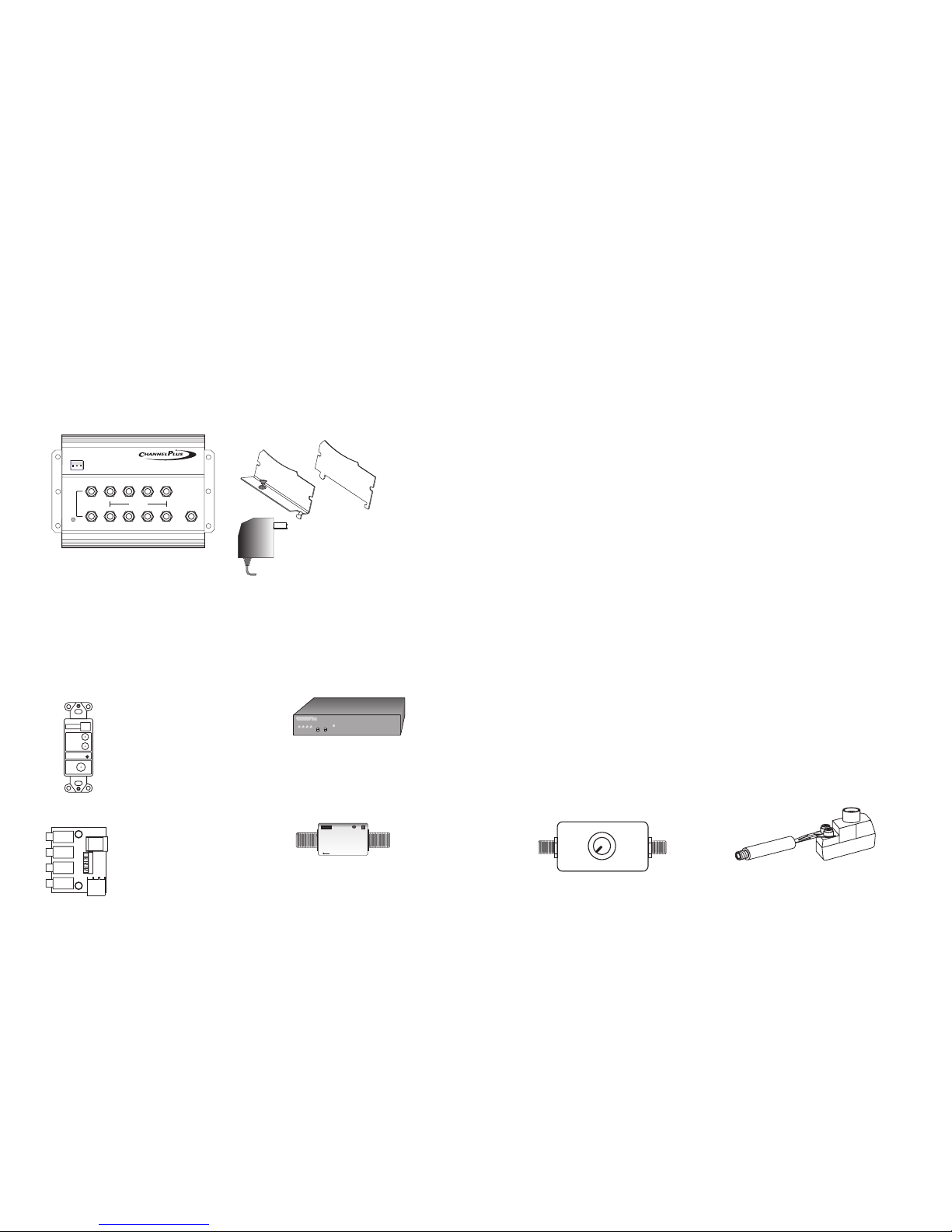
Contents: DA-8200
Additonal mounting ears*
Power Supply (15VDC @ 300mA)
*Additional mounting
ears are designed to
allow the DA-8200 series
to be OpenHouse grid
compatible.
®
Model Differences:
The DA-8200 is for antenna or uni-directional cable systems. The HHR has the
highest headroom of any coax panel available in the market. Systems will meet FCC
part 15 requirements for using modulators with an antenna based system.
The DA-8200 is for bi-directional cable systems, providing a 5-42MHz back
channel for cable modems or interactive set-top boxes.
HHR
BID
IR
EMITTERS
POWER
15VDC
SYSTEM POWER
FROM
MODULATOR
VIDEO SYSTEM
Accessories:
Model 2010
Power injector wall plate
Powers the DA-8200
remotely and has a built-in
IR wall plate.
(fits standard Decora)
Model 2184 IR breakout
replaces the power
supply adapter and
drives up to four IR
emitters.
TO EXPANSION PANEL
Model 2181 IR extender allows
IR signals to be passed from
one DA-8200 to another.
high headroom3X8coax panel for antenna or cable systems
mod input
ir out
gnd
A
B
+15vdc
5v, multi-room ir remote control
(pwr)
ant/catv
DA-8200HHR
tv output
TM
Series 5500 and series SVM
modulators create local TV
channels, have built-in IR
engines and can remotely
power the DA-8200.
The model DA-8200 is the heart of a multi-room video distribution system.
The DA-8200 connects as many as 8 televisions to cable or antenna, while
maintaining compatibility with ChannelPlus video modulators and the 5V IR
repeating system.
Model DA-8200
®
model 5545 quad digital modulator
pll frequency control
D
C
BA
program
select
THIS PRODUCTS COMPLIES WITH FCC REQUIREMENTS.
THE DA-8200HHR IS SUITABLE FOR USE WITH AN ANTENNA OR WITH CATV
SYSTEMS.
THE DA-8200BID IS SUITABLE FOR USE WITH CATV SYSTEMS.
A SYSTEM USING THIS
DEVICE WILL COMPLY WITH FCC REQUIREMENTS. USE ONLY VIDEO
MODULATORS THAT COMPLY WITH PART 15 OF THE FCC RULES AND HAVE A
25dBmV MAX OUTPUT LEVEL. FAILURE TO DO SO MAY VOID THE USER’S
AUTHORITY TO OPERATE THIS EQUIPMENT.
Things To Watch For:
Herringbone interference on modulator channel (diagonal lines):
Herringbone interference on many channels, including modulator
channels (disappears when you remove the CATV/antenna feed):
You
may have chosen a channel number that is not completely vacant. Distant UHF
stations may not be watchable, but will cause interference if you try to create a
new channel at the same frequency. Also, cable companies often have extra
signals where there should be none. Try moving the modulator channel to another
number. You may have to add a low pass filter to remove the cable company noise.
If the filter does not work, try adding a DC-block to remove common mode
interference.
The
RF amplifier can be overloaded by abnormally strong signals. Often, you can cure
the problem with a simple attenuator. Use a variable attenuator and try to find a
signal level where the interference just disappears. Sometimes, the problem is one
station is far stronger than the rest. In this case, attenuating all of the signals with a
simple attenuator will cause the desired stations to be weak (snowy). You must
reduce the strength of the only offending station. A common FM trap will help if the
problem is a nearby FM tower. If the problem is a nearby TV station, often the
station management can provide suitable filters.
We recommend using only RG-6 coax when wiring a house. Why? Although good
RG-59 has only slightly more loss than RG-6, it is harder to find a good RG-59 with
wide bandwidth. RG-6 is a little more expensive and a little harder to run (it is
thicker). But you will avoid surprises if you stick to RG-6.
0dB
5dB
20dB
15dB
10dB
min max
Inexpensive variable
attenuator Inexpensive high pass
filter and DC block
7
FCC Requirements:
SCALE SHEET
SIZE
A
Date
Unless otherwise specified, dimensions
are in inches and tolerances are:
Material:
Finish:
Eng:
Drg:
.X ± .03 .XX ± .01 .XXX ± .005
Rev
Brea, CA 92821-6213
3001 Enterprise Street
multiplex
technology, inc.
®

high headroom3X8coax panel for antenna or cable systems
mod input
ir out
gnd
A
B
+15vdc
5v, multi-room ir remote control
(pwr)
ant/catv
DA-8200HHR
tv output
TM
high headroom3X8coax panel for antenna or cable systems
mod input
ir out
gnd
A
B
+15vdc
5v, multi-room ir remote control
(pwr)
ant/catv
DA-8200HHR
tv output
TM
high headroom3X8coax panel for antenna or cable systems
mod input
ir out
gnd
A
B
+15vdc
5v, multi-room ir remote control
(pwr)
ant/catv
DA-8200HHR
tv output
TM
CATV or
Antenna
Master DA-8200
Up to 64 TV outlets
You may connect up to 8
more DA-8200s to the
outputs of a DA-
8200, for a total of 64 TV
outlets. The longest
recommended coax run
should not exceed 150’.
That is a total of the coax
from to and
to TV.
master
master slave
slave
Slave DA-8200
Expanding the DA-8200:
Each DA-8200 must be powered individually. Each DA-8200 can have local
modulators and a zoned IR system for TVs connected to the eight outputs. Any
modulator signals injected into a will be viewable only on the eight
TVs connected to it. Modulators connected to the DA-8200 will be viewable
on all TV outputs including DA-8200s. To combine IR control signals of
units, use one 2181 IR extender for each DA-8200.
slave
slave DA-8200
master
slave slave
DA-8200 slave
(See model 2181 instruction manual)
Circuit Breaker:
6
The model 2010, DA-8200 and modulators with remote-power feature have built-in
circuit breakers. If any of the power LEDs are not lit, reset the circuit breaker by
disconnecting and reconnecting all power supplies. If the system does not reset,
look for an installation error.
A
B
(pwr)
12v, two-way multi-room ir remote control
mod input
tv out
DA-8200
Power LED
Power LED
Model
2010
IR
EMITTERS
POWER
15VDC
SYSTEM POWER
FROM
MODULATOR
VIDEO SYSTEM
TOEXPANSIONPANEL
Model 2181
high headroom 3X8coaxpanel for antenna or cable systems
mod input
ir out
gnd
A
B
+15vdc
5v, multi-room ir remote control
(pwr)
ant/catv
DA-8200HHR
tv output
TM
high headroom3X8coaxpanel for antenna or cable systems
mod input
ir out
gnd
A
B
+15vdc
5v, multi-room ir remote control
(pwr)
ant/catv
DA-8200HHR
tv output
TM
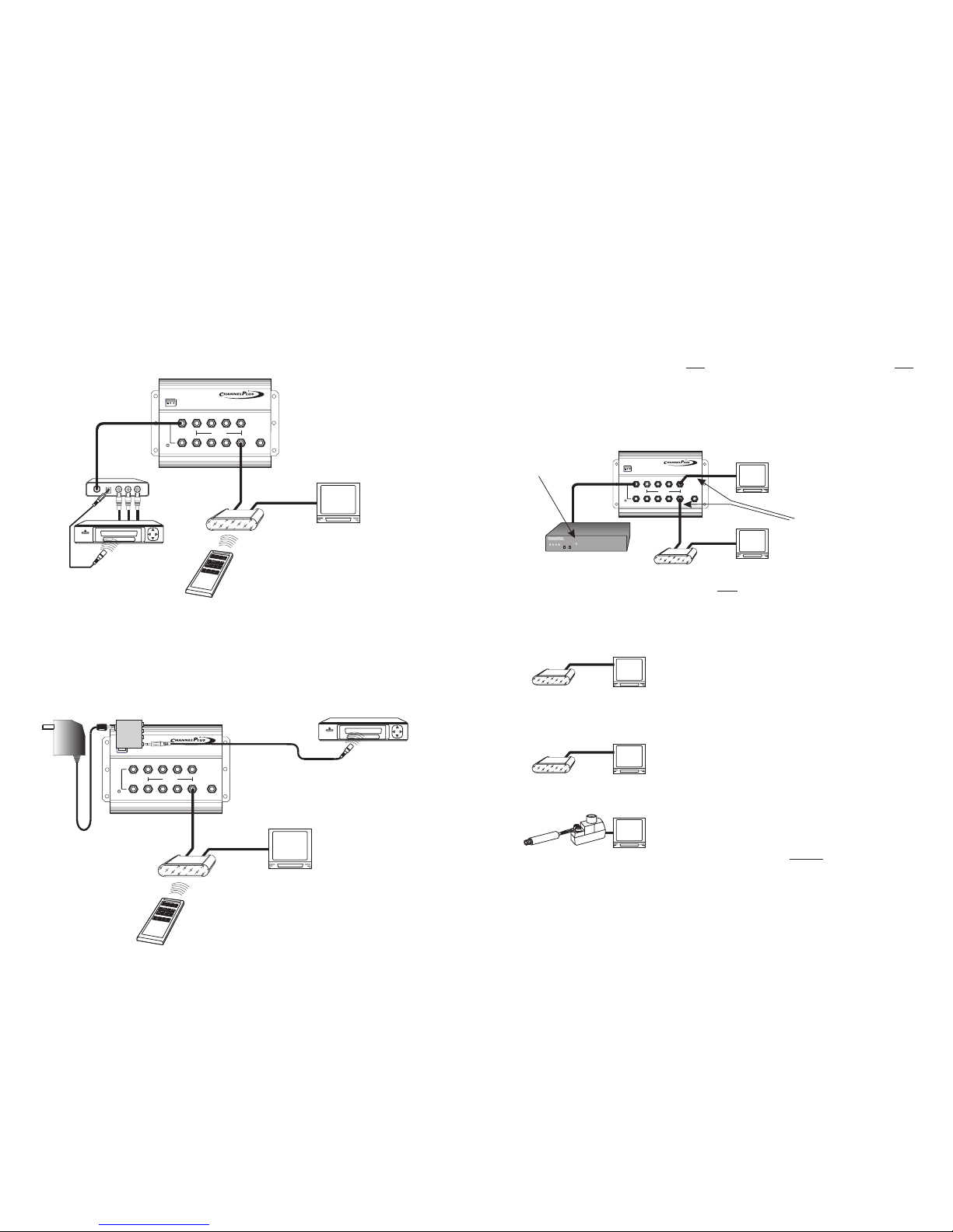
Typical Installation:
Remote Powering the DA-8200
The DA-8200 works like a zero-loss splitter. The signals you put on the
antenna/CATV input will appear on the outputs with about 3dB of gain.
LOOP
VIDEO
AUDIOAUDIO
POWER
OUTPUT
DVD, VCR
or Satellite
2010 power
injector
Up to 8 TVs
RG-6 coax is
recommended
for all runs (not
to exceed 105’
total)
CATV or
Antenna
LOOP
VIDEO
AUDIOAUDIO
POWER
OUTPUT
DVD, VCR
or Satellite
Modulator
Modulator may be
connected to A or B input.
For remote power and IR,
connect only to input B.
Important:
To remote power, use input B.
Put the DA-8200 coax panel where the coax is: often the basement or garage.
The single coax carries power, RF signals and IR repeating signals. You can
remote power the DA-8200 from series 5500 or series SVM modulators, or from a
model 2010 wall plate.
IR
EMITTERS
POWER
15VDC
SYSTEM POWER
FROM
MODULATOR
VIDEO SYSTEM
3
SCALE SHEET
SIZE
A
Date
Unless otherwise specified, dimensions
are in inches and tolerances are:
Material:
Finish:
Eng:
Drg:
.X ± .03 .XX ± .01 .XXX ± .005
Rev
Brea, CA 92821-6213
3001 Enterprise Street
multiplex
technology, inc.
®
high headroom 3 X 8 coax panel for antenna or cable systems
mod input
ir out
gnd
A
B
+15vdc
5v, multi-room ir remote control
(pwr)
ant/catv
DA-8200HHR
tv output
TM
4
2184 IR breakout
supports 4 IR emitters
5V IR Repeating System:
With the DA-8200 you can control your video devices from any room in the
house. Any or all 8 outputs may be connected to model 2133 IR targets.
Direct your remote control at the IR target and the 2173 IR emitter will
repeat the IR signal to the video devices in the media room.
Normally, the IR emitters are connected to the modulator or 2010 wall
plate. But, if the coax panel is located in the media center, you may chose
to connect the emitters to a model 2184 IR breakout panel.
high headroom3X8coax panel for antenna or cable systems
mod input
ir out
gnd
A
B
+15vdc
5v, multi-room ir remote control
(pwr)
ant/catv
DA-8200HHR
tv output
TM
ChannelPlus
modulator
Model 2133
IR target
Typical
remote control
Model 2173
IR emitter
Model 2133
IR target
Model 2173
IR emitter
Typical
remote control
IR information is only
available on port B
VCR, DVD or
sat receiver
5
IR Systems: FAQ
!
!
!
There are two common IR repeating systems. The 12V
system is very versatile and intended for professional installation. The
5V system used by the DA-8200 is easy to use and low cost.
12V and 5V IR targets are interchangeable. The emitters
interchangeable.
When using a 5V IR system, DC blocks are usually not necessary.
not are
Xantech®
5V IR Systems: Troubleshooting
high headroom 3X8coaxpanel for antenna or cable systems
mod input
ir out
gnd
A
B
+15vdc
5v, multi-roomir remote control
(pwr)
ant/catv
DA-8200HHR
tv output
TM
®
model 5545 quad digital modulator
pll frequency control
D
C
BA
program
select
1) If IR light glows
steadily, there is noise
entering the system.
2) First disconnect the
coax cables from all of the
television output jacks. Find
the source of the noise by
re-connecting cables one at a time until the IR light glows. This identifies that coax
as a noise source. Connect this noisy coax for the next steps.only Remember that
there could be more than one source of noise, so you may need to repeat the
following steps for each coax. Now step 3 will determine which type of noise
problem you have.
3a) Optical noise. Cover the target with a towel.
If the IR lights stops blinking, you have optical noise.
The target may be pointed at a window, a
fluorescent light or a plasma TV. Reposition the
target so it can’t “see” the source of IR light. If the IR
light still glows, proceed to the next step.
Shade the target
3b) EMI noise: TV sets are sources of EMI,
electromagnetic interference. Move the target
away from the TV and try to reposition the target so
the IR light stays off. If the IR light still glows, proceed
to the next step.
Move the target
3c) Conducted noise from the TV. If the noise is
not optical or EMI, then you have a noisy TV. Some
TV sets generate substantial low frequency
electrical noise on their The sensitive IR
detection circuits can be triggered by this noise. Use a high pass filter to remove
the noise. Sometimes a DC block will be a effective filter. The assembly shown
at left is a low cost sure fix for this problem. Create this filter from two different
types of matching transformers. Connect the filter directly to the F-connector
on any noisy TV. Note that any TV can be a noise problem, with or without an IR
target attached.
inputs!
Install high pass filter
TV set
is ON
TV set
is ON
TV set
is ON
TV set
is ON
TV set
is ON
ChannelPlus
modulator
SCALE SHEET
SIZE
A
Date
Unless otherwise specified, dimensions
are in inches and tolerances are:
Material:
Finish:
Eng:
Drg:
.X ± .03 .XX ± .01 .XXX ± .005
Rev
Brea, CA 92821-6213
3001 Enterprise Street
multiplex
technology, inc.
®
This manual suits for next models
1
Table of contents
Other Channel Plus Amplifier manuals

Channel Plus
Channel Plus 3425 User manual

Channel Plus
Channel Plus DA-500A Manual

Channel Plus
Channel Plus MDS-6A User manual

Channel Plus
Channel Plus CHANNEL PLUS 5115BID User manual

Channel Plus
Channel Plus CHANNELPLUS MDS-6 User manual

Channel Plus
Channel Plus DA-506BID User manual

Channel Plus
Channel Plus CHANNELPLUS MDS-6 User manual
Popular Amplifier manuals by other brands

Technics
Technics SU-G50 Service manual

Electro-Voice
Electro-Voice AP2600A owner's manual

Sound Ordnance
Sound Ordnance M350-1 manual

EDWARDS SYSTEMS TECHNOLOGY
EDWARDS SYSTEMS TECHNOLOGY AA75 Series installation manual

Harman
Harman crown DriveCore Install DA Series Operation manual

GA Project
GA Project PRE-573 manual


