manuals.online logo
Brands
  1. Home
  2. •
  3. Brands
  4. •
  5. Technics
  6. •
  7. Amplifier
  8. •
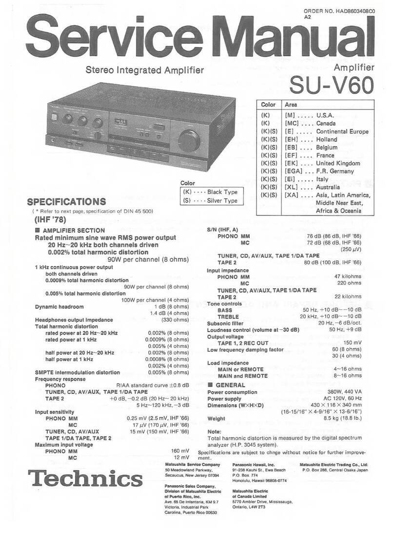
  9. Technics SU-G50 User manual

Technics SU-G50 User manual

Service
Manual
Stereo
Integrated
Amplifier
SPECIFICATIONS
(DIN
45
500)
m
AMPLIFIER
SECTION
40
Hz~20
kHz
continuous
power
output
both
channels
driven
2x85
W
(8Q)
DIN
power
output
2x
100
W
(8Q)
Total
harmonic
distortion
rated
power
at
40
Hz~20
kHz
0.09%
(8Q)
rated
power
at
1
kHz
0.05%
(8Q)
half
power
at
1
kHz
0.03%
(8Q)
Intermodulation.distortion
rated
power
at
50
Hz:
7
kHz=4:1,
SMPTE,
80
0.09%
Power
bandwidth
both
channels
driven,
—3 dB
10
Hz~20
kHz
(8Q,
THD
0.09%)
Residual
hum
and
noise
1mvV
Input
sensitivity
and
impedance
PHONO
2.5
mV/47
kQ
TUNER,
CD,
TAPE,
VCR
2/TV,
VCR
1/EQ
150
mV/47
kQO
PHONO
maximum
input
voltage
(1
kHz,
RMS)
128
mV
(135
mV,
IHF
’66)
S/N
rated
power
(80)
PHONO
71
dB
(IHF
66:
78
dB)
TUNER,
CD,
TAPE,
VCR
2/TV,
VCR
1/EQ
70
dB
(IHF
66:
90
dB)
Frequency
response
PHONO
RIAA
standard
curve
+0.8
dB
(30
Hz~
15
kHz)
TUNER,
CD,
TAPE,
VCR
2/TV,
VCR
1/EQ
10
Hz~80
kHz
(+0,
—3
dB)
Technics
Matsushita
Electric
Industrial
Co.,
Ltd.
Central
P.O.
Box
288,
Osaka
530-91,
Japan
ORDER
NO.
AD9006159C7
Amplifier
SU-G50
Color
(K)
in
ccsnecas
Black
Type
Area
Asia,
Latin
America,
(GC)
Middle
Near
East
and
Africa
Oceania
Far
East-PX
(K)
Tone
controls
BASS
50
Hz,
+10
dB~—10
dB
TREBLE
20
kHz,
+10
dB~—10dB
Super
bass
80
Hz,
+6
dB
Muting
—20
dB
Output
voltage
TAPE,
VCR
1/EQ
REC
OUT
150
mV
Channel
balance,
CD
250
Hz~6,300
Hz
+1dB
Channel
separation,
CD,
1
kHz
50
dB
Headphones
output
level
and
impedance
670
mV/3300.
Load
impedance
AorB
80~160Q
AandB
80~160
m@
GENERAL
Power
consumption
510
W
Power
supply
For
Oceania:
AC
50
Hz/60
Hz,
240
V
For
others:
AC
50
Hz/60
Hz,
110
V/127
V/220
V/240
V
Dimensions
(WxHxD)
430
x
130.5x310
mm
(161%/6"x5%e"x
1272")
Weight
7.6
kg
(16.7
Ib.)
Notes:
1.
Specifications
are
subject
to
change
without
notice.
2.
Weight
and
dimensions
are
approximate.
3.
Total
harmonic
distortion
is
measured
by
the
digital
spectrum
analyzer.
Panasonic
Tokyo
Sales
Department
Matsushita
Electric
Industrial
Co.,
Ltd.
World
Trade
Center
Bldg.,
4-1,
Hamamatsu-cho,
2-chome,
Minato-ku,
Tokyo
405,
Japan
SU-G50
m@
CONTENTS
Page
Page
BEFORE
REPAIR:
ici
.cshdaecescasebass
cece
achat
$oond
ce0d
2
SCHEMATIC
DIAGRAM
...........
0000
cece
eee
ees
13~18
PROTECTION
CIRCUITRY
........
00.
cece
cece
eee
e
nee
eee
2
PRINTED
CIRCUIT
BOARDS
.............0.00
cee
ees
19~22
ACCESSORIES
....0
20.0...
ccc
cece
cence
tence
ee
enes
2
TERMINAL
GUIDE
OF
IC’S,
LOCATION
OF
CONTROLS
...........
00-0
e
ccc
ce
eee
ee
eee
3,4
TRANSISTORS
AND
DIODES
............
00000
e
eee
e
eee
22
CONNECTIONS
220...
e
nee
e
renee
4~6
WIRING
CONNECTION
DIAGRAM
............-2.-0
200s
eee
23
DISASSEMBLY
INSTRUCTIONS
................0000.0
eae
7~9
REPLACEMENT
PARTS
LIST
...........-00000
0s
eee
24~28
DESCRIPTION
OF
FLPANEL
...............0c
eee
eeeeeeee
10
-
EXPLODED
VIEW
......
0...
cece
cece
eee
29,
30
BLOCK
DIAGRAM
.............0
0c
cece
cece
eee
e
teenies
11,12
m@
BEFORE
REPAIR
(1)
Turn
off
the
power
supply.
Using
a
10,
5
W
resistor
connect
both
ends
of
power
supply
capacitors
(C701,
C702,
10000
LF)
in
order
to
discharge
the
voltage.
(2)
Before
turning
the
power
supply
on,
after
completion
of
repair,
slowly
apply
the
primary
voltage
by
using
a
power
supply
voltage
controller
to
make
sure
that
the
consumed
current
at
50
Hz/60
Hz
in
NO
SIGNAL
mode
should
be
shown
below
with
respect
to
supply
voltage
110
V/127 V/220
V/240
V.
Power
supply
voltage
AC
110
V
AC
127V
AC
220
V
AC
240
V
Consumed
current
50
Hz
260~510
mA
300~550
mA
100~400
mA
80~330
mA
Consumed
current
60
Hz
208~408
mA
240~440
mA
80~320
mA
64~264
mA
m
PROTECTION
CIRCUITRY
The
protection
circuitry
may
have
operated
if
either
of
the
following
conditions
is
noticed:
*No
sound
is
heard
when
the
power
is
switched
ON.
*Sound
stops
during
a
performance.
The
function
of
this
circuitry
is
to
prevent
circuitry
damage
if,
for
example,
the
positive
and
negative
speaker
connection
wires
are
“shorted”,
or
if
speaker
systems
with
an
impedance
less
than
the
indicated
rated
impedance
of
this
unit
are
used.
If
this
occurs,
follow
the
procedure
outlined
below:
1.
Switch
OFF
the
power.
2.
Determine
the
cause
of
the
problem
and
correct
it.
3.
Switch
ON
the
power
once
again.
Note:
When
the
protection
circuitry
functions,
the
unit
will
not
operate
unless
the
power
is
first
switched
OFF
and
then
ON
again.
m@
ACCESSORIES
¢
AC
power
supply
cord
(SJA173)...For
(GN)
area
only.
(RJA0004)...For
others.
@AC
attachment
plug
(SJP9215)...For
(GC),
(PX)
areas.
Configuration
of
AC
power
supply
cord
differs
according
to area.
ey
ees
nC
ee
Oe
ee
ae
ae
mm
LOCATION
OF
CONTROLS
Front
panel
SU-G50
[1]
Power
switch
(power)
[2]
Peak-power
indicators
(power
level)
These
indicators
indicate
the
peak
power
value
of
the
output
level
to
the
speaker
systems.
[3]
Input
selector/volume
level
display
(input)
This
display
usually
shows
the
sound
source
selected
by
the
input
selectors;
when
the
volume-control
is
used
to
adjust
the
volume
level,
the
level
is
displayed
in
decibel
for
about
two
seconds,
after
which
the
display
returns
again
to
indica-
tion
of
the
sound
source.
[4]
Muting
indicator
({mute|
)
This
indicator
will
illuminate
when
the
muting
button
on
the
remote-control
transmitter
(not
included)
is
pressed.
(Refer
to
the
operating
instructions
of
the
component
with
which
the
remote-control
unit
is
included.)
To
cancel
the
muting
function
without
using
the
remote-con-
trol
transmitter,
press
and
hold
the
‘‘phono”
input
selector
of
this
unit
for
about
4
seconds.
Note:
The
unit
will
switch
to
the
phono
mode.
[5]
Volume
indicator
(volume
level)
Indicates
the
volume
output
level
at
a
glance.
Super
bass
switch/indicator
(super
bass)
Low
frequency
sounds
are
reinforced
when
this
switch
is
pressed.
The
indicator
will
illuminate.
Volume
control
(volume)
Input
selectors/indicators
(input
selector)
These
selectors
are
used
to
select
the
sound
source
to
be
heard,
such
as
a
disc,
radio
broadcasts,
etc.
The
correspon-
ding
input
selector
indicator
illuminates
during
operation
to
indicate
the
selected
sound
source.
The
selected
sound
source
is
also
displayed
on
the
input
selector/volume
level
display.
[9]
Balance
control
(balance)
This
control
is
used
to
adjust
the
left/right
volume
balance.
VCR
1-monitor
switch/indicator
(monitor)
Set
this
switch
to
the
ON
position
(so
that
the
indicator
above
is
illuminated)
when
using
a
graphic
equalizer
o,
playing
back
or
monitoring
the
sound
from
a
VCR
connecied
to
the
“VCR
1/EQ”
terminals.
This
selector
should
be
set
to
the
OFF
position
(indicator
off)
at
all
other
times.
[14]
Tone
controls
(bass/treble)
The
bass
control
is
used
to
adjust
the
low-frequency
sound
range,
and
the
treble
control
is
used
to
adjust
tihe
high-
frequency
sound
range.
[12]
Speaker
selectors
(speakers)
These
selectors
are
used
to
turn
the
speaker
system
S
on
and
off.
[13]
Headphones
jack
(phones)
SU-G50
eRear
panel
COOLING
FAN
AC
OUTLETS
For
(GC)
(PX)
areas
i)
fl
[@D|—_+ae
INLET
G—jpvourace
SELECTOR
For
(GC)
(PX)
areas
AC
OUTLET
For
(GC)
(PX)
areas
SPEAKER
A
SPEAKER
B
TO
TAPE
TO
TUNE
R
|
REMOTE
CONTROL
Phono
input
capacitance
is
about
100
pF.
m@
CONNECTIONS
Make
connections
to
each
component
in
the
system
by
using
stereo
connection
cables
(not
included).
A|
[GND]
|B}
{C
D|
[REMOTE
CONTROL
(TUNER)|
[REMOTE
CONTROL
(TAPE)
EME
“PHONO”
terminals
Connect
a
turntable.
Connect
a
compact
disc
player.
a
L
©)
©
Compact
disc
player
?
(not
inc
tuded)
Turntable
(not
included)
R
©)
a
ED
©)
LINE
OUT
ii
®
v
A
W
==
®
wo
AR)
GND)
terminal
This
terminal
is
for
use
with
a
turntable
which
has
a
ground
wire.
FOR
oe
EE
a
Fe
ears
[c]
“TAPE”
terminals
Connect
a
tape
deck.
7
TAPE
REC
QUT
PLAYBACK
Cassette
deck
(not
included)
LINE
IN
LINE
OUT
@i
|
REMOTE
CONTROL
(TAPE)
terminal
This
terminal!
is
used
to
connect
a
Technics
tape
deck
with
the
control
terminal.
rey
“vcr
2/TV”
terminals
Connect
a
second
video
cassette
recorder
or
TV.
©
|
VCR
(not
included)
(R)
0
®
[F
|
“VCR
1/EQ”
terminals
Connect
a
video
cassette
recorder
or
a
graphic
equalizer.
—VORI/EQ—,
Graphic
equalizer
(not
included)
©
©
LINEIN
O
©
LINE
OUT
“TUNER”
terminals
Connect
a
tuner.
[o]
(not
included)
cb
REMOTE
CONTROL
®
¢
—_®
©
Wi
[REMOTE
CONTROL
(TUNER)
terminal
This
terminal
is
used
to
connect
a
Technics
tuner
with
the
control
terminal.
Connect
the
L-type
cable
(included).
[ele
“PRE
OUT/MAIN
IN”
terminals
Do
not
remove
the
shorting
pins
from
these
terminals
unless
you
plan
to
use
an
independent
preamplifier
or
main
amplifier.
(No
sound
will
be
heard
if
they
are
removed).
To
use
it
in
this
way,
consult
the
operating
instructions
for
the
additional
amplifier
or
preamplifier
that
you
plan
to
use.
io)
2
Q&S
[H|
Cooling
fan
The
cooling
fan
operates
at
high
output
power
levels
only.
|AC
OUTLETS||~AC
IN
SPEAKERS
(See
text
at
right.)
“AC
OUTLETS”
(UNSWITCHED)
Power
is
always
available,
regardless
of
power
switch.
Audio
equipment
rated
up
to
60
W
(total
for
all
outlets)
can
be
connected
here.
For
(GC),
(PX)
areas.
AC
power
supply
cord
Connect
the
AC
power
supply
cord
(included)
after
all
other
cables
and
cords
are
connected.
Tuner
(not
included)
AC
power
supply
cord
(included)
If
this
unit
is
not
to
be
con-
nected
with
the
tuner
This
unit
Househoid
AC
outlet
SU-G50
Connection
to
speaker
systems
Two
pairs
of
speaker
systems
(main,
second)
can
be
connected
to
this
unit.
Speaker
systems
that
can
be
connected
(to
any
of
the
speaker
connection
terminals
of
this
unit)
are
speaker
systems
with
an
impedance
of
8
to
16
ohms.
Main
speaker
systems
(not
included)
Connect
to
the
“A”
terminals.
(left)
Second
speaker
systems
(not
included)
Connect
to
the
‘‘B”
terminals.
(right)
(left)
To
connect
cords
to
terminals
@
Strip
off
the
outer
@D
covering,
and
twist
the
——s=
>
=
center
conductor.
15mm
Twist
(19/32”’)
@
Tilt
the
lever
back
and
insert
the
cord.
@
P=
Vel
@)
Close
the
lever
and
pull
the
cord
gently
to
be
sure
that
it
is
secure.
ANS
Note:
Be
sure
to
only
connect
positive
(+)
cords
tcpo
sitive
(+)
terminals,
and
negative
(—)
cords
to
negative
¢
—)
terminals.
Note:
To
prevent
damage
to
circuitry,
never
short-circuit
the
plus
(+)
and
minus
(—)
speaker
cords.
m@
DISASSEMBLY
INSTRUCTIONS
“ATTENTION
SERVICER”
Some
chassis
components
may
have
sharp
edges.
Be
careful
when
disassembling
and
servicing.
eae
Removal
of
the
Cabinet
Procedure
1
2)
Cabinet
lo
Front
Panel
1.
Remove
the
2
flat
cables
(CN601,
CN602).
2.
Remove
the
3
screws
(Q@~®).
3.
Remove
the
front
panel
in
the
direction
of
the
arrow.
Remove
the
6
screws
(Q@~@).
Removal
of
the
Power
Switch/
Speakers/Headphones
P.C.B.
Procedure
1-2-3
Power
Switch
/Speakers
/Headphones
P.C.B.
Front
Panel
How
to
remove
the
flat
cable
1.
Lift
the
connector.
2.
Pull
out
the
flat
cable.
Flat
cable
a
|
Connector
OZ
a
Ref.
No.
4
Procedure
152-54
@
Volume/FL
P.C.B.
1.
Pull
out
the
1
knob
(@).
2.
Remove
the
1
nut
(@).
3.
Remove
the
5
screws
(Q@~@).
@
Operation
P.C.B.
1.
Pullout
the
3
knobs
(@~@®).
2.
Remove
the
10
screws
(@~@).
a
Check
of
the
main
P.C.B.
Procedure
15
3.
Remove
the
3
screws
(O~@®).
4.
Remove
the
front
panel
in
the
direction
of
the
arrow.
Ref.
No.
6
Procedure
1-5-6
Regulator
Transistor
1.
Unsolder
the
power
IC
or
regulator
transistor.
2.
Remove
the
4
screws
(@~Q).
When
mounting
the
power
IC
or
regulator
transistor.
Apply
silicone
compond
(SZZOL15)
to
the
rear
side
of
power
IC
or
regulator
transistor.
Bottom
Chassis
5.
Remove
the
bottom
chassis
in
the
direction
of
the
arrow.
6.
Reinstall
the
front
panel
to
the
main
P.C.B.
eee
Removal
of
the
Power
Transformer
Procedure
17
Power
Transformer
1.
Remove
the
flat
cable
(CN701).
2.
Remove
the
4
screws
(@~@).
fe
ee
ee
eee
tae
Ref.
No.
Removal
of
the
Rear
Panel
Ref.
No.
Removal
of
the
AC
Outlet/AC
Iniet
8
9
P.C.B.
Procedure
Procedure
138
1-8-9
Rear
panel
1.
Remove
the
connector
(CN651).
2.
Remove
the
13
screws
(Q@~®).
3.
Remove
the
rear
panel
in
the
direction
of
the
arrow.
e
Release
the
8
claws.
Procedure
1-810
.
Release
the
3
claws.
(See
Fig.
1)
2.
Insert
a
screwdriver
at
the
root
of
the
cooling
fan.
Force
it
out
of
the
motor
shaft.
(See
Fig.
2)
3.
Remove
the
motor
cover
by
used
©
screwdriver.
(See
Fig.
3)
4.
Remove
the
motor
from
the
fan
casing.
(See
Fig.
4)
5.
When
mounting
the
motor
fan,
align
the
fan
casing’s
projection
with
the
hole
of
the fan
motor.
(See
Fig.
5)
Fan
case
Cooling
fan
Projection
(Fig.
2)
Fan
motor
(Fig.
5)
m@
DESCRIPTION
OF
FL
PANEL
[FL901
(RSL0044-F))
eGRID
ASSIGNMENT
7G
ePIN
CONNECTION
Pane
PEPE]
F/FININ|
8
PIN
NO.
CONNECTION
a
N
H
aif
el]
||
6G
SG 4G
3G
26
AN
|
At
LT
ICAL
|
ang
[A
We
SE
RAE
TD
VINE
VASE
LINE
PLD
o
Opoppap
a
a
ogegnos}
a
a
m@
BLOCK
DIAGRAM
MAIN
IN
O
n
n
v
SVI3206A4
HEADPHONES
°
PRE OUT
POWER
AMP
AN6558F
rea
M5218P
M5218P
=
ual
M5238P
ie
51
IC551
Ce)
Ge)
ATTENUATOR
eo----
s601-2
R
AMP
pes
AMP
SUPER
BASS
AMP
a)
EQUALIZE
\
28
ce
BUFFER
AMP
(VOLUME
CONTROL)
4
1
{81
i
i}
Rea
ee
2)
I;
on
9
(6)
=]
|
|
sip
Gel
saeaa
i
0
:
|
A
BS
ua)
V2,
a
1,
5
|
©
off
dO
?
?
(134
>
d
a
PHONO
5
1
Y
!
i
SPEAKERS
rE
I
oe
o-
I
|
ron
!
Ea
1
|
o—
1
4
8
1
}
=
i
|
i]
|
A
]
|
1
<1
Ns,
]
ea
I
|
—_)
TUNER
|
@
|
13!
|
!
(Leh)
(tL
eh)
| !
|
8
Switching
|
[Ac
det.
]
det.
O
iter
e
|
io
control
|
mi
ene
|
4
ogo
RLY6O!
8
<>
!
——
|
fr}
83}
PREC
OUT
i]
|
0651,652
veneest
ares
ben
Is
|
(22)
(20)
aed
224
ato
?
1
(Leh)
8
ae
H
°
2,
3
{sé
+
1
!
-—rEc
out
C=
0
|
(Leh)
¢
fot
rez
ot
1
Tc9163N
H
haan
1C401
a
Boot
|
|
!
!
I
INPUT
|
090119902)
|
I
j
SELECTOR
L
?
PLAYBACK
(O;
1
------------~,-1
®
wena
(ich)
|
I
=r
!
=
_l
t
\
I
1
CK2]
15
1
VCR2/TV
1
ee
!
eee
|
(
)indicates
pin
No.
of
right
channel
Q701,0705
isi
(VOLTAGE
ADJ.)
Q705,
0706
s701
T7O1
-——_
(POWER)
D70I~704
RECT
AC
IN
+
6
21
22__
fas
0708,0709
r-----
J
oak
al
al
ala
el
ce
at
oe
a
a
eeieateateietatedemtet
|
_
DT2
sT2 ck2 CLK
DaTA
STB
S.BASS
o
I
|
’
(UNSWITCHED)
I
\
710,715
Power
+o
H
transformer,
LJ
MN
M50940-194SP
|
AC
OUTLETS
ea
Lc)
\
|
|
MICROCOMPUTER
|
(UNSWITCHED)
X
OUT
ra
x901
1
I
(4MHz)
l
!
\
|
!
Ea
L
REM
REC
vRO
VARI
Kal
pg——~_
2
sio—_-s1
AVec
Vee
.
VP
a
a
ce
aie
es
a
Sa et
es
ase
ero
ee
ar
ee
eo
eee
ee
ee
(UNSWITCHED)
25
5
8 9
6
44
51
53
62
63
64
38
——________
en
asl
To
FL
DISPLAY
0907,
910
TUNER
Q913~915
C8) Gs)
Cs)
control
—
REMOTE
drive
aa
oe
CONTROL
ki
Vo
VR9O1
S90I~
906
(ENCODE
VOLUM
KEY
Le
JARS
e
MATRIX
FL9OI
(FL
DISPLAY)
To
POWER
TRANSFORMER
a
0927,
re
ee
ais
1
2
3
4 5 6
7
8 9
10
m@
SCHEMATIC
DIAGRAM
BY
main
circuit
(Parts
liston
pages
24~27.)
(This
schematic
diagram
may
be
modified
at
any
time
with
the
development
of
new
technology.)
GND
YQ
e3vi00
+
poles:
AN6S58F
2
1¢530
S
1C40
@S601-1,
601-2
:
Speaker
selector
switches.
ee
ace
PHONO
EO:AMP
R461
RAS
M5238P
TC9212P
[S601-1:
A,
S601-2:
B]
:
\
Aap
ey
BUFFER
AMP
ATTENUATOR
aie
‘
P
"gece!
ee
R459
c457
|
C459
R467
(VOLUME)
S701
:
Power
switch
in
“on”
position.
peo
ee
Pye
Bd
Ua
at
aki
SRE
eS751
:
Voltage
selector
switch
in
“110
V”
position.
PHONO
cai
(110
V/127
V/220 V/240
V)
L
6
|
aye
si
HA
Uy
Roch
&
For
(GC),
(PX)
areas
JK40I-
1
Fo
Rasi C451
Se
B]
s901~906
:
Input
selector
switches.
vv
oman
—
a
fl
og
5
Ae
ole
a
$901:
Phono,
$902:
Tuner
Sloe
|
‘el
hf
eT
od
<8
eT
$903:
CD,
S904:
Tape
ann
eos
3/8]
z
S|
¢
z|
3
$905:
VCR
2/TV,
S906:
VCR
1
S
cot
ptt
S907
:
Super
bass
switch.
aes
2
|
Slow
a)
ol
S|
x
sl
5
ox
#85
53S:
sl
ef
3
Sle
84
8]
——R
ch
3%
E85
gy
53°
Taf
5]
5
wey
=e
27
*
CDePhono
signal
line
Recording
signal
Tes
|
z2
Shr
af
mee
gt
S|
&
Bie
ow
ls
Positive
voltage
line
----—
Negative
voltage
line
UREN
43
iLs*
|
Rab2e20
.
case
a
an
0
&
=
an
C462
35V4.7
mee
¥
.
»
K
t=;
mo
Indicated
voltage
values
are
the
standard
values
for
the
unit
measured
by
:
8
tae
ee
i;
tw
Riis
22K
cola
|
the
DC
electronic
circuit
tester
(high-impedance)
with
the
chassis
taken
as
68
6.022
6800"
|
oi
EEE
YY
eld
Cc
standard.
Therefore,
there
may
exist
some
errors
in
the
voltage
values,
Teor
|
is
depending
on
the
internal
impedance
of
the
DC
circuit
tester.
e|mportant
safety
notice:
Components
identified
by
A
mark
have
special
characteristics
important
for
safety.
When
replacing
any
of
these
components,
use
only
manufacturer's
specified
parts.
5
ic4ol
ital
©
TCOI63N
R417
100K
*Caution!
[28h
A
rae
¢
INPUT
SELECTOR
IC
and
LSI
are
sensitive
to
static
electricity.
TK
S08
Ne
7
sane
a
rao
b
Secondary
trouble
can
be
prevented
by
taking
care
furing
repair.
4
*Cover
the
parts
boxes
made
of
plastics
with
aluminum
foil.
aa
nch
Gara
—
{=
fe
R590
220K
R591.
56K
*Ground
the
soldering
iron.
-
REC
OUT
D
*Put
a
conductive
mat
on
the
word
table
.
t
‘——
L
ch
-
VR552-1
*Do
not
touch
the
legs
of
IC
or
LSI
with
the
fingers
directly.
Jka02~2
DATA
cL
(assy
es
’
3
$
0K
5
TAPE
012
get
=
z
[sr
sh
STB
GNO
=
BS
"
PLAY
BACK
rea:
sen
ieee
Power
Supply
circuit
For
(GN)
area.
_
&,
=
os
aah
Sak
+
f——R
ch
ioc
sas
oT
N=
R555
RST
POWER
SWITCH/SPEAKERS/
ae
3.9K
;
WE
HEADPHONES
JACK
CIRCUIT
REC
OUT
7
t
i]
al
age,
|
ip
=
ov
Lov
[aS
o>
te
—
£
:
8
E
ace
JK
404~1
‘
=
ae
@)-@)
OF
A
as
VCR
1/
EQ
8
14BV
&
as
I
2
t
C791
0.01
ee
7
eh
.
6
E>
PLAYBACK
Recording
if
signal(ich)
5
——
Loch
JK
404-2
1
|
5
R556
@
o
220P
3.9K
R558
3.9K
2
5
°
3
'
SB]
Sy
s
[7
3
f
ed
gt
2
1C551,552
2 |
M5218P
x
TONE/SUPER
A
2
3x
BASS
AMP
F
{
F
fSe7eon
2
cs62
@
837
2
|
tooKtc)
laoKiey”
g
|
(BASS)
(TREBLE)
a
gs
3g
gs
|
[EJ
OPERATION
CIRCUIT
|
a13=
=14=
10
11
12
13
16
17
18 19
Q505
aon
2SA933SQRSTA
Paes
550
ei
MUTING
CONT.
{ft
R505
100K
0.922
ley
a
ee
Fy
Bae
PEE
ons
i
amv
.
SRNR
ERERETN
PRED
ae
a
ee
eee
|
Die
0927
oev
iv
R522_10K
i
Mad
06BMTA
0928
MA4O68MTA
520
0.01
t—+
++
R521
100k
o
2
Qa
i-g
a
i-2
a
Qa
ia
oO
CN9O!
R891
10
AWW
A
barra
CY
Qo
2
_
(>)
©
CS
=e
cl
()
oS
ma
oo
o
cr
Sy
"Boon
ease
ORORONGHON
ORONO
=
OROMOLONORORON
CNSOI
CN902
Q913~915
j
ov
UN42I1ITA
Q
503,504
7
ss
FL901(RSLOO44—-F)
FL
DRIVE
Scere
pepe!
anes
Oca
ene
=
28C3327ABTP
=F
EOROKOKORORORO
PMUTING
bye
3
HM
‘
FL
DISPLAY
35V47
R516
2.2K
oF
+
a
=
|
|
x
|
2
:
28
23)—
C2)
~~“
9)“
©,
fo]
|
CNSOI
|
Ee
|
i
'
2)
)_C)
©)
+
i
zl
a
i
1
|
|
}
bal
aes
e|
8g
a7
ty
27
tay
JST
Je
1ST
:
|
SL
Ech
ee
TST
BTL
BL
aL
ED
BI
ED
el
Al
|
aa
—
a,
Rage
o]+
0
f+
o
8
it le
ee
o
va
aes
70}
Ce)
(es)
2
oT
let
sv
let
le
<
Ry
B
2.2,
BLELELBLELE
8
GG)
G6)
Or)
Oxon
LOR
GAC
Ai
m
at
Us
4B
3
Uys
Le
Ls
Lt
Us
so
Lig
Le
cNsol
Sl
SL
:
:
ay.
“sed
|
403
wo
Soc
_—
ssi
:
UN4IIITA
eS
|
8B
ea
a
babe
SWITCHING
CONT.
LAL
-
ey
©
2
ims
20vV
/0t¥
gs
=
rl
r+
278
R934.
33
=
8°
|
Q403
2
83
R590
220K
R591
56K
10
4y
62v
a
re
CY
B
0901
90!
Baa
£3
—62V
1S$291TA
100pH
°
Sy
VR5S2-1
3]
s
63
+3
1OOKIC)
Q551
5-7
ssh
8
2
°
el
uaa
ae
g
Q551,552
1C901
Set
gs
a
Bom
2
2SK301RSTA
(eri)
M50940-I194SP
“18
ow
g
SWITCHING
$923.
238
dlov
|&
Sa
270
MICRO
COMPUTER
p90 att
Bx
4
(SUPER
BASS:ON)
-——
Ney
IMAIGSTA
MAIGSTA
Oi)
oe
—
a
Si
>
o o
3
|
a
2h
O-G
5
w904
aay
33
>.
3
“
e
fy
f\
tie.
Sie
gJV\ie
08S
|
OSus
2v°D
BY]
oo]
Rs7s
ik
R583
2.2k
;
2!
r4
4
801
:
.
Rs73h
R937
10K
4
{tame
)
in
icy
:
!
e
0917
xb
*
3
ov
fov
gov
x
R929
100
7
sos.
=
S
ao
bb
¢c¢@aibie
bc
a
fete
cy
a
@-@®
ea
1.
©
2
oor
ge
2
rae
a
2
be
be
ett
:
Tec
|e
|||
|
a
Ti
fy
1OOK(G)
ae
8
Mohs
Ne
|
BALANCE)
(TUNER)
ns
™
=
OBy
3
3]
(VOLUME
)
9905
roy
ei
a
VR901
ROI6
=
8
>
rape)
.
.
BE
«s.]
Q907
23
7
‘
v
be
ge
28
=
C—O)
—-®)
22!
R933
100
l0k\
S\
485
v
°
aaa
14.8V
14
BV
-~\
on
ay
Ov
9940
1.2K
48
A)
=
BS
°
EN
D
3)
N =
S!0K
*
oe
+
ROTA
pio
R584
(vera/tv)
7
“
-
0922
%
-
e
“A
+
wee
Sat
=
LNOBI516
PM
5
BASS
on
fe
Aaa
5
Reba
9K
a
TET
Ree
|
aN
R932
100
8
&
(SUPER
BASS)
3
asio
&
eT
$7
we
‘o
o
sare
0917~921,923
ae
1C551,552
x
ENoTiiGRw
29
R931
150
rr
stud
ov
(9k
ose
|
M5218P
°
oe
Se
7
ie
2
Ss
(co)
as
iit
am
Fes
ue
«
!
f
TONE/SUPER
2
23
2
|
ge
b
BASS
AMP
=
(6)
(s)
3
if
os
A
a
>
em
&
Q901,902
i
«
7
€
4°
2SC1740SQSTA
S s
L
3
R969
ROEB_SCRIGT
~—RIEE
5
R962
ROE!
3
{
§
g
68K
47K
33K
2.2K
1K
820
a
?
BUFFER
AMP
L
vrss2-2
Lee
if
>
3
edeba
0905,
906
e910,
912
<
>.
fooK
ic)
2
S
2
iS
=
ee
UN421ITA
—UN4211TA
28
9907
{EREBLE.!
=
2
5
Cs
2
=
LED
DRIVE
SWITCHING
a3
2SA933SQRSTA
L
4
e
S
ba is
=
(REMOTE/RESET)
SWITCHING
8
rs
)
[
3
8
8
g
$
3
(REMOTE
|
:
a
a
a
3
oO
-
48y
|
IT
[B]
votumevry
prive
circuit
|
~15—
416%
21
22 23 24
25 26
27
28
1
2
m@
PRINTED
CIRCUIT
BOARDS
i
aaa
|
"6nd
PHONO
TUNER
[co
rm
A
R659
A
R660
A
ree!
CN65!
vk405-1
Boy
Len
ow
9K405-2
or
oeel
/2W
22
\/2W
22
1/2w
22
(REC
OUT)
;
‘a
O)
“=O
Ace!
Q65!
®,
z
‘0;
can
ie
le
SVI3206A
2SCI740SQSTA
x)
38
Fan
A
ouT
IN
POWER
AMP
MOTOR
DRIVE
S
“14
BV
28
Cc
pm
ot
Ic60!
8
z
,
()
)
b
—)z
©
8
nao
e
Reh
-14
BV
R656
ae
eth
=
10K
|
J
Q652
CP
Bt
ba
ef
x
3
_
e
x
x|
x
x
x
&
5S
° N
as
8
3
8
[+
i
=
ra
6
2V
=
ee
re
8
8 3
S
JK6O!
As
sf
a
ala
Owes
te
Sa
ape
wife
cainnt
‘
Sat
S
Leh
a
8
OV
9652
)
9705
3
a
2SA933SQRSTA
v7
(a)
~-278v
2SC3940AQSTA
8
q
Pe
a
pai
|
ox
MOTOR
DRIVE
+
ww
REGULATOR
:
oF,
a
@
Rch—
a
|
O
ial
ak
$
0722
®lelaPe
1K602
SPEAKERS
B
UN421ITA
spesals
¢
4)
STABILIZER
S|
s8e27T2
=
g
[8
REO?
56
©
Leh
|
K
|
a3
+
=
(By)
——
08
t
607
10P
7
28
+
@)
3
za
Rch~
nS
wos
1
Be
an
=
a
3e
ee7
ee
5
g
<
O
=
x|
= g
8x
=
2
oS
3
S
@
g-
a
2
<
by
ey
fe
eu;
2 =
so
8s
<
53
5
cneoza|
cnsozel
|
GO
OOO
OROROBEORONOM
ee
hes
— 7
cers
CNGO2A
eo
oO)
Q70l
2SDI761DEF
bedi
REGULATOR
2SA992EF
TA
RELAY
DRIVE
JK604
HEADPHONES
&
ra
ss
(SPEAKERS
}
3
!
Useoi-!
=
(a)
=
e
[
"gan
oo
o
x
Os
=|
=
!
:
3%
2F
=
<
1
<
7
2
~
ve
oa
1
c
i
=
a
<q
-a
g|
E84
o\.
€
=7
3
x
A
s701
5
-15.2V
=
.
2)
2
AFI
Tan
{
POWER
}
E
F*)
s|
As
=8at
‘ee
CN7OIB~
1
OND
oo
714
BV
72
R80
SS
38
+
A
Q7io
qr
53
C791
0.01
Tz
a
os
4
iy
S
a
|
gee
Q
38
t+,
1
K
°
ie
|
2
:
Bs
I
!
Py
POWER
SWITCH/
||
<oqr
a|
xd
83
e
SPEAKERS/
i
~
5
2
awl
ere
bz
HEADPHONES
JACK
|
2
5
=
RTTT
B
7)
olf]
ivaw
82
CIRCUIT
a
al
-27
BV
-627V
wa
ts
A
.
.
A
Q708
()
®
4
if
iene
7
T
a
ux704|
A
3K703
JK702
JK7O!
F
a
a
&
1
Q708,710
é
ca)é
é
<
lL
ac
110/127
7/
220
/
240V
|
i
2SBII87DEF
=
=
=
(50/60Hz
}
ui
REGULATOR
2
g
®
a
ai
7
2
3|7
o
He
+
+
|
A
AK
|
i
ae
A
%
uA
4
ac
outLets-—~
‘,
Se
ere
Ne
"S
ouumnanine
omnanenit
Ga
AC
IN/AC
OUTLETS
CIRCUIT
—17—
—18-—
[PHONO
|
[TUNER
|
co
VCR
1/EQ|
[REMOTE
CONTROL
(TUNER)
SPEAKERS
|-—
(REC
OUT)
(PLAYBACK)
reoBkF
a
ret
Ab
VOLUME/FL
DRIVE
PC.B.
MAIN
P.C.B.
gonna
Ag
Sp
Sa
“Rees
°°
$902
:
.
(TUNER
PRE
OUT
|
[MAIN
IN
REMOTE
CONTROL
[—{SPEAKERS
|—
(TUNER)
(TAPE)
rotBr
a
RAR
SS
R
ch
L
ch
Roch
che,
C
VOLUME/FL
DRIVE
P.C.B.
|
:
see
ae
3
2
>
cecil!
enn
fp
MAIN
P.C.B.
OPERATION
P.C.B.
.
:
essences
®sinsiannmnnemand
-
es
—i1y—
—20-
SU-G50
15
16
17
Power
Supply
For
(GC,PX)
areas.
19
EE
IN/AC
OUTLETS
P.C.B.
'
AC
IN
AC
OUTLET
(MOZI27/220/240V
50/60Hz
)
(
UNSWITCHED
)
|
@
|
JK7
JK70
'
JK7
JK7O
22
——
pies
es
o
om
|
|
fe
(rd;
'
(
UNSWITCHED
)
(
UNSWITCHED)
L___fae
outtets
}—!
rem]
|
r.
For
[GN]
area.
TE
AC
IN
PC.B.
A
(
240V,
50/60Hz
)
BRN——”
BRN
BLU
WHT
WHT
WHT
WHT
|
|
|
Ait
SPEAKERS
DOWER
(B) (a)
(s601-2)[-](S601-1)
(S701)
qo
!
|
|
|
|
&
:
|
i
|
Bex
|
@
G
é
1
9
;
F4
T2A
‘2
C
POWER
SWITCH/
SPEAKERS
/
HEADPHONES
JACK
P.C.B.
l27V
tov
40V,
127
[p)
vorsce
ADJ.
P.C.B.
240Vv
\
No
(S751)
VOLTAGE
WHT
——
WHT
For
(GN)
a
-
red.
23
For
(GN)
area.
PHONES
24
SPEAKERS
(A)
(S601-2)
(S60
I-1)
POWER
SWITCH/
SPEAKERS
/HEADPHONES
gy
POWER
(S701)
C7
@
TERMINAL
GUIDE
OF
IC’S,
TRANSISTO
AN6558F
M5218P
M5238-1
UN4111TA
UN4211TA
Cc
B
2SB1187DEF
MA165TA
2SD1761DEF
MA167ATA
1SS291TA
Ca
oa
Cathode
A
2SA992EFTA
MA4056MTA
MA4068MTA
Ca
cS
Cathode
oe
Anode
TC9212P
"1
1
2SC3940AQST.
E
CB
MA4150MTA
MA4270MTA
c
206°
Cathode
CS
Anode
a
SU-G50
SU-G50
23 24
25
26
@
WIRING
CONNECTION
DIAGRAM
m
REPLACEME
For
(GN)
area.
REMOTE
MaAIN|
|
PRE
|
(VCRIZEQ
|
Ivcr2|
|
TAPE
co
PHONO
|
[6ND
Notes
:
*
Important
safety
POWER
SWITCH/SPEAKERS
/HEADPHONES
JACK
PC.B.
[SPEAKERS
|,
CONTROL
IN
|
[OUT
|
ee
oun
ZY
(REC
OUT)
Components
identi
'
rAd},
ri
Bh,
(TAPE)
(TUNER)
aegis
(PLAYBACK)
components
use
on
PHONES
SB
ee
6
fa
ono
Te
fel
*
The
parenthesized
:
JK
405
JK404
j
vK403
/]
JK402
|
vK401
Parts
without
theg
JK902
JK9O!
IcN6éoza
CN6O2B
Ref.
No.
Part
No.
Part
Na
annenan
wn
FAN
MOTOR
TC9163N
M5238P-1
AN6558F
IC,
PHONO
Eq
1¢9212P
By
vain
ec.
W5218P
SVI3206A
IC,
POWER
A
W50940-194SP
|IC,
MICRO
Cd
CNT7OIA-|
CN70IB-I
UN4111
{2803327-A
TRANSISTOR
2SA933SQR
TRANSISTOR
(
=H)
:
2SK301RSTA
|
TRANSISTOR
2SA992EFTA
|
TRANSISTOR
g
;
a
;
2SC1740SQ
|
TRANSISTOR
[el
vovume/r
orive
Pcs.
perA
J
oreration
pce
peal
Um
cnt
estta
isos
2SD1761DEF
|
TRANSISTOR
E
|
je0d
2SC3940AQSTA
|
TRANSISTOR
E
aie
|2SB1187DEF
|
TRANSISTOR
one
cnees
3
|
UN4211
TRANSISTOR
5
CN901
CN902
CN903
|
CNSOI
2 c
7
0
R
JINAL
GUIDE
OF
IC’S,
TRANSISTORS
AND
DIODES
os
[ssi
CNSOI
UNa211
TRANSISTOR
M5238-1
AN6558F
TC9212P
TC9163N
M50940-194SP
AC
IN]
[AC
OUTLET
2SA993SQR
|
TRANSISTOR
(
UNSWITCHED)
UN4211
15
33
AC
IN/
UN4211
AC
OUTLETS
PCB.
|
EtG
BRN
>
UN4111TA
2SA933SQRSTA
Fake
UN4211TA
2SC1740SQSTA
POWER
SWITCH
SPEAK
R
/
—<SSreS=
(UNSWITCHED
)(UNSWITCHED
)
28C3327-A
M
teadpHoNes
vack
PCB
a
camer
BTN
Bovey,
1.
PJ
voitace
aby.
P.c.8)
ESOODLE
eLK
MA4150M
cn6oz8
Heth
roa)
@)
BLK
MA4068M
Pee
CN6O!
eu
WAI65
MA167
MA165TA
MA4056MTA MA4150MTA
LNO71516PM
ine
|
MA167ATA
MA4068MTA
MA4270MTA
LNO81516PM
MA4270
1SS291TA
ae
es
ei
wAdiSOM
[DIODE
>
Ls
Cathode
Sgr
Sates
rer
0
[sPeaKers]
[POWER]
19s291TA
[DIODE
A
ya
A
os
Cathode
[PHONES]
MAL65
DIODE
A—®)=
ca
MAL65
DIODE
ne pe
MAAOSOMTA
[DIODE
—22—
—23-
SU-G50
SU-G50
—L
@
WIRING
CONNECTION
DIAGRAM
@
REPLACEMENT
PARTS
LIST
REMOTE
main]
{pre
|
[VeR!7E0
|
[vcra]
[
TAPE
€)
PHONO
|
/GNO
Notes
:
*
Important
safety
notice:
CONTROL
ab:
OUT
irec
oun
(REC
OUT)
Components
identified
by
A\
mark
have
special
characteristics
important
for
safety.
When
replacing
any
of
these
HAL
By
(TAPE)
(TUNER)
(PLAYBACK
(PLAYBACK)
ee
(eager
components
use
only
manufacturer’s
specified
parts.
A
h
eo
oO
[
*
The
parenthesized
indications
in
the
Remarks columns
specify
the
areas.
(Refer
to
the
cover
page
for
area.)
yk6o!
||
sKeEoz
JK
405
JK404
j
JK403
i
uk402
|
Jk40l
Parts
without
these
indications
can
be
used
for
all
areas.
ICN6O2A
CN602B8
CN7OIA-1_CN70IB-1
[fe]
CN6O!
38
JK902
JK9OI
FAN
MOTOR
VOLUME/FL
DRIVE
PCB.
CN90I
CN902
CN903
CN90!
CN902
CN903
TT
A
a
a
a
a
a
AT
a
Aa
A
aT
a
A
a
fa
TIT]
TIT
«
ITIITI
a
A
ZZ
22
TF
A
(227
a
Ca
8
Cal
S
AC
OUTLETS
PC.B.
CNSOI
CN5O!
EE}
operation
pce
[ac
in]
[ac
ouTLET
(
UNSWITCHED)
AC
IN/
POWER
SWITCH
SPEAKERS
/
HEADPHONES
JACK
PCB.
(B)
(A)
SPEAKERS
T7OI(
Power
transformer)
(UNSWITCHED
)
(UNSWITCHED
)
AC
OUTLETS
By
voutace
apy.
Pcs.
S751
(
VOLTAGE
WHT
WHT
BLK
WHT
Tar
ao
WHT
WHT
—23—
BLK
Part
Name
&
Description
INTEGRATED
CIRCUIT
(S)
LNO71516PM
Part
Name
&
Description
LED
BLOCK
Remarks
+
LNO81516PM
LED
TC9163N
IC,
INPUT
SELECTOR
DIODE
+
10402
M5238P-1
IC,
BUFFER
AMP.
MA4068M
}——
+
1C451
AN6558F
TC,
PHONO
EQ
AMP.
VARIABLE RESISTOR
(S)
10530
1C9212P
IC,
ATTENUATOR
(VOLUME)
10551,
552
|M5218P
IC,
TONE/SUPER
BASS
AMP.
EVJYA1F02C15
BASS/TREBLE
CONTROL
1¢601
SVI3206A
IC,
POWER
AMP.
EVJO2QF02615
BALANCE CONTROL
M50940-194SP
IC,
MICRO
COMPOUTER
EVQHQAF
25248
MAIN
VOL.
CONTROL
TRANSISTOR
(S)
COIL
(S)
[UN4IL
TRANSISTOR
SLOYO7G-40
‘cot
Q503,
504
=
|28C3327-A
TRANSISTOR
RLQZP1O1KT-Y
|COIL
Q505
2SA933SQR
[TawsisTOR
E
Q551,
552
|2SK301RSTA
|
TRANSISTOR
TRANSFORMER
(S)
Q601
2SA992EFTA
|
TRANSISTOR
Q651
2SC1740SQ
TRANSISTOR
/RIP1PSE002
POWER
TRANSFORMER
A\
(GC,
PX)
Q652
[2sa933SqR
TRANSISTOR
RTP1PSBO02
[POWER
TRANSFORMER
A\(GN)
2SD1761DEF
TRANSISTOR
2SC3940AQSTA
TRANSISTOR
OSCILLATOR
(S)
Q708
2SB1187DEF
—
|
TRANSISTOR
Q710
2SB1187DEF
—
|
TRANSISTOR
|EFOGc4004s4
OSCILLATOR
Q722
UN4211
TRANSISTOR
Q901,
902
|28¢1
740SQ
{TRANSISTOR
DISPLAY
TUBE
Q905,
906
|UN4211
TRANSISTOR
|
Q907
2SA933SQR
~
TRANSISTOR
|RSLOO44-F
DISPLAY
TUBE
Q910
[unazit
TRANSISTOR
UN4211
TRANSISTOR
FUSE
(S)
DIODE
(S)
XBA2C40TBO
FUSE
250V
4A
A\
(GC,
PX)
]xBA2¢207B0
FUSE
250V
2A
A
(GN)
D601
MA165
DIODE
XBAZC2OTBO
[FUSE
250V
2A
[A
GC,
PX)
D651
MA165
[DIODE
i!
D652
Naaoem
[DIODE
SWITCH
(ES)
D701-704
|
P300DLE
DIODE
D705
MA4150M
DIODE
|ssuzize
SH,
SP
SELECTOR
A/B
D706
MA4068M
«DIODE
ESB8249V
_|SW,
POWER
A
p707~—Ss«MAL65
DIODE
ESE37263
_|SW,
VOLTAGE
SELECTOR
Z\
(GC,
PX)
MA167
DIODE
EVQ21405R
SW,
INPUT
SELECTOR/S.
BASS
MA4270
DIODE
fs
MA4150M
DIODE
JACK
(S)
1SS291TA
DIODE
D905-913
—
|MA165
DIODE
+
SJF3069N
TERMINAL
BOARD
D915
|uat6s
RJROOS4M
D916
MA4OS6MTA
‘[biove
DIODE
QJA04552C
ine
TERMINAL
HP.
JACK
Ref.
No.
Part
No.
Part Name
&
Description
Remarks
3K701
$J89231-1B
AC.
INLET
As
(CC,
PX)
3K701
$ys9234B
[AC
INLET
AGN)
JK702-704
|$J89233B
AC
OUTLET
AM
(GC,
PX)
JK901
RJJ33TRO1
|
REMOTE
(TUNER)
JK902
RJJ33TROL
|
REMOTE
(TAPE)
CN5o1
_|RITOO3KOO@Mi
[CONNECTOR
(BP)
i
CN5OI
RJUOOSKOO8M1
|SOCKET(8P)
MAIN
P.
C.B.
CN6O1
RJSIAI703
[CONNECTOR
(3P)
CN601
RJSIA1703
[CONNECTOR
(3P)
CN65I
$J73213
CONNECTOR
(2P)
|
CN9O1
RJTOO3KDO8M1
|
CONNECTOR
(8P)
CNg01
RJUOO3KOO8M1
|SOCKET(8P)
MAIN
P. C.
B.
cn902
RJTOO3KOO8M1
|
CONNECTOR
(8P)
CN902
IRIUOO3KOO8M1
[SOCKET
(BP)
MAIN
P.
C.B.
CN903
|
RITOO3KOO8M1
[CONNECTOR
(8P)
[
(N903
[RJUOO3KOO@MI
[SOCKET(8P)
MAIN
P.
C.B.
CN602A
RJSIA1704
—-
|
SOCKET
(4P)
cNoozA
—_|RISIAL704
|
SOCKET(4P)
|
CN701A
_[RJSIAL705
|
CONNECTOR
(5P)
CN602B
(RJSIAL704__|SOCKET(4P)
|
CN602B
|RJSIAL704
|
SOCKET(4P)
[cN701B
_|RJSLAL703
|
CONNECTOR
(3P)
RELAY
ae
ee
RLY601
——
|SSy134
RELAY
|
|
-
1
[
|
|
|
T
4
|
|
a
+
+
*
Resistance
values
are
in
ohas,
unless
specified
otherwise,
1K=1,
000
(OHM)
,
1M=1,
000k
(OHM)
Part
No.
Values
&
Remarks
Values
&
Remarks
man
8
ERDS2TJ271
1/4¥
270
|
Notes
:
*
Capacity
valuse
are
in
microfarads
(uF)
unless
specified
otherwise,
P=Pico-farads
(pF)
F=Farads
(F)
14h
47K
AN
RESISTORS
1/w
=
680
A
ERDS2TJ122
W330
ERDS2TJ104
ERDS2TJ470
|
1/4W
47
ERDS2TJ222
1/48
2.
2K
ERDS2TJ
102
ERDS2TJ104
ERDS2TJ
102
ERDS2TJ103
ERDS2TJ473
1/AW
47K
ERDS2TJ104
1/4¥
100K
ERDS2TJ102
1/4W¥
1K
R623
ERDS2TJ684
1/4W
=
680K
R624
ERDS2TJ103
1/48
10K
A
R627
ERDS2TJ154
1/4W
150K
ERDS2TJ222
1/4AW
2.2K
R628
ERDS2TJ684
1/4W
680K
ERDS2TJ821
R417,
418
jERDS2TJ104
1/4W
100K
R651-654
~_|enosztu2z3
1/4W
22K
ERDS2TJ102
R421
ERDS2TJ332
|
1/4¥
3.3K
R43i-444
|ERDS2TJ102
|
1/4¥
1K
R451,
452
|ERDS2TJ821
|
1/4W
820
R453,
454
ERDS2TJ224T
|
1/4
220K
R455,
456
ERDS2TJ563
|
1/4W
56K
R457,
458
[erosoran
1/aW
270
R459,
460
lERDS2TJ680T
|
1/4¥
68
R461,
462
|ERDS2TJ184T
|
1/4¥
180K
ERDS2TJI23.
|
1/4W
12K
ERDS2TJ563
|
1/4
56K
ERDS2TJ392T
|
1/4¥
3.
9K
ERDS2TJ103
|
1/4¥
10K
ERDS2TJ223
|
1/4¥
22K
ERDSIFVJ220T
|
1/2
22
A
ERDSIFJ330
|
1/2
33
A\(GC,
PX)
ERD2ECVG330T
|
1/4W
33
AN(GN)
ERDS2TJ272T
|
1/4¥
2.
7K
ERDS21N223
|
1/4W
22K
ERDS2TJ103
|
1/4"
10K
ERDS2TJ682T
|
1/4W
6.8K
A\
ERDS2TJ
122
ERDS2TJ152
R965
ERDS2TJ182
|
1/4W
1.8K
ERDS2TJ222
ERDS2TJ332
TERDs2TJ
472
ERDS2TJ682T
R971
ERDS2TJ104
1/4¥
100K
”yERDS2TJ102
1/4W
1K
R716
ERDS2TJ222
1/4W
2.
2K
ERDS2TJ104
1/4¥
100K
R717
ERD25FVJ150T
|
1/4
15
A
ECBTIHLOLKBS
|
SOV
100P
C409,
410
JECKRIHLO3ZF5
|
SOV
0.
O1U
C411,
412
_|ECEAIVU4R?
ECKRUHLO3ZFS
|
SOV
0.
O1U
ECEAQJUI0IB
|
6.3V
100U
ECEALCK220
|
16V
22U
ECBTIHLO1KBS
|
SOV
100P
ECBTIHLO1KBS
|
50V
—
100P
ECEAIWU4R?
=|
35V
4.70
ECBTIHLO1KBS
|
SOV
100P
ECBTIHLO2KBS
|
50V
1000P
ECFRIEZ23KR
|
25V
0.0220
ECFRIE682KR
|
25V
6800P
ECEALWAR?
|
35V
4.70
16V22U
RAGS,
466
R467,
468
R505,
506
R515,
516
|ERDS2TJ222
|
1/4W
2.
2K
R517,
518
|ERDS2TJ102
|
1/4¥
1K
R520
ERDS2TJ394
ERDS2TJ104
|
1/4W
100K
EROS2TJ103
|
1/4W
10K
BROS2TJ474_
|
1/4W
470K
ERDSZTJ392T
|
1/4W
3.
9K
ERDSZTJI83T
|
1/4¥
18K
ERDS2TJ332_
|
1/4¥
3.3K
ERDSZTJI22
|
1/4W
1.2K
ERDS2TJ821
|
1/4
820
ERDS2TJ223
|
1/4W
22K
ERDS2TJS63
|
1/4W
56K
ERDS2TJ102
|
1/4W
1K
BRDS2TJ471
|
1/4
470
ERDSZTJ682T
|
1/4¥
6.8K
1/4W
820K
2
|
AW
2.2K
1/4W
220K
56K
1K
56K
1.
8K
56K
R771
ERDSIFVJ180T
|
1/2W
18
AX
(GC,
PX)
R771
ERD2FCVG180T
|
1/4¥
18
A\(GN)
R773
ERDS2TJ123
1/W
12K
A
ERD25FVJ8R2T
ERDSIFVJ180T
ERDS2TJ100
ERDS2TJ104
ERDS2TJ273
ERDS2TJ104
ERDS2TJ274
ERDS2TJ153
ERDS2TJ104
1/44
1K
1/4¥
4.
7K
ERDS2TJ562
|
1/4W
5,
SK
Wan
2.7K
1/4"
10K
1/4¥
3.
9K
1/48
220K
face
[oo
ir,
R931
ERDS2TJ151
1/48
150
ERDS2TJ101
1/4¥
100
1/4¥
33
ERDS2TJ101
1/¥
=
100
1/48
=
10K
ECKRIH103ZF5
ECEALCK100B
ECEA1VU4R7
IV
4
ECBT1E2232ZF
25V
0.
022U
ECBT1H150J5
SOV.
s15P
ECBT1H221KBS
|
50V
220P
ECBT1H330J5
SOV. «33P
ECEALCPS100
16V.
100
ECFRIEI23KR
|
25V
0.012U
ECFRIE683KR
|
25V
0.
068U
ECFRIES62KR
|
25V
5S600P
0531,
532
C535-538
0553,
554
(557,
558
C563,
564
C565,
566
10
A
1/4W
22K
47
fy
Values
&
Remarks
ECFRIE273KR
|
25V
0.027U
lecealcpsi00
|
lev
10U
ECKRIH1032F5
|
50V
0.
O1U
ECFRIELOAKR
|
25V
0.
1U
ECEAIVUAR?
|
35V
4.
7U
ECKRIH391KB5
|
50V
390P
ECEAIcU220
|
16V
22U
ECCRIHLOOKCS
|
SOV
10P
ECCRIHISLACS
|
SOV
150P
ECFRIE223KR
|
25V
0.022U
EcEAlvua70
=|
35V
47U
ECEAIHU330
|
50V
33U
ECEAZAUI00
|
100V
100
ECEA2AN2R2SB
|
100V
2.2U
A\
ECKDIH681KB
|
SOV
680P
ECEAIHKO10B
|
50V
IU
ECES71V103UX
|
71V
100000
A\
ECKRIHIO3ZF5
|
SOV
O.01U
AV
ECEAICKI00B
|
16V
10U
“[ecenantoszes
|
Sov
0.
o1v
ECEAZANZR2SB
|
100V
2.
2U
ECKRIHIO3ZF5
|
50V
0.01U
A\
ECKRIH1032F5
|
50V
0.
O1U
C712
ECEAIWU470
|
35V
470
A
C771
ECKR2H1032U
|
S00V
0.01U
A\
(791
ECKWKC1O3PF2
|
400V
0.01U
A
901
ECEAQJU102
6.3¥
1000U
ECBT1C103MS5
|
16V
0.
01U
ECEAQJUG71
|
6.3V
470U
TECEALMUR7B
|
SOV
0.47U
EcealMuo10
|
Sov
1U
ECBT1C103MS5
|
16V
0.
O1U
ECFRIES63KR
|
25V
0.
O56U
ECEAIMU2R2
|
50V
2.20
ECEAIVU330
|
35V
33U
jeceatMaR?
|
SOV
4.70
EeBTic272MR5
|
16V_2700P
[BcBTins3iKBs
|
SOV
330P
EcBriEz2szF
|
25V
0.0220
1}
|
|
THT
|
—27-—
Part
Name
&
Description
Part
Name
&
Description
ACCESSORIES
BOX
Remarks
CABINET
PARTS
t
ACCESSORIES
RKMOO16A-K
CABINET
aon
SNE2129-1
SCREW
INSTRUCTIONS
MANUAL
ASS’
Y
(GC)
XTBS3+8JFZ1
SCREW
INSTRUCTIONS
MANUAL
ASS’
Y
(GN)
(RowO071
PAIN
VOL.
KNOB
INSTRUCTIONS
MANUAL
ASS’
Y
(PX)
RGWO072
TONE
KNOB
INSTRUCTIONS
MANUAL
(GC)
RGROO8OE-B
REAR
PANEL
INSTRUCTIONS
MANUAL
(GN)
{RGROOSOF-F
1
REAR
PANEL
INSTRUCTIONS
MANUAL
(PX)
RGROO80E-A
He
REAR
PANEL
WARRANTY
CARD
(GN)
RGUOO30
POWER
BUTTON
(PX)
RGUO101
SP
BUTTON
WARRANTY
CARD
SERVICENTOR
LIST
(GC,
GN)
_{RGUO350
SUPER
BASS
BUTTON
AC
CORD
A
GC,
PX)
RGUO349-1
SELECT
BUTTON
AC
CORD
A
()
1
SHE187-2
HOLDER
REMOTE
CORD
SJP9205-2T
SHORTING
PIN
AC
ATTACHMENT
PLUG
A\
(GC,
PX)
SJS9233A
AC
OUTLET
COVER
(GC,
PX)
SJS9231A
AC
INLET
COVER
(GC,
PX)
SJS9234A
[AC
INLET
COVER
(GN)
RFKJUG70P-K
CHASSIS
ASS’
Y
SKL293
FOOT
SNE2123
SUS894-1
GND
SCREW
SPRING
SYE1128-3
FAN
ASS’
Y
SHE232
FAN
SUS271
SPRING
SHE233
MDN-4RB4MRC
SHE234
FAN
CASE
CAP
[$J7783
TERMINAL
SJS§215
SOCKET
RFKNUG70P-K1
PANEL
LIGHT
PANEL
LIGHT
RFKGUGSOP-K
RFKNUG70P-K3
FRONT
PANEL
ASS’
Y
SHR9861
SNE4021-1
FL
HOLDER
NUT
|
EYFS2BC
FUSE
HOLDER
XTBS26+8J
SCREW
XTBS+14J
SCREW
a
SCREW
[XTB3+20J
XTB3+8JFZ
SCREW
XTWS3+8T
{screw
RMA0317
ANGLE
RMZ0111
SHEET
a
PACKING
MATELIAL
+
RPGOS44
CARTON
BOX
RPGOS45
CARTON
BOX
PAD
eax
XZB52X60A012
PROTECTION
COVER
23(Refer
to
the
figure
below)
J
(GC.
PX)areas.
SU-G50
SU-G50
m
EXPLODED
VIEW
1
cacti
sain
casuasioiasssieisaie
ica
RI
RR
DCCA
AISNE
ALAN
OHSS
PC
INNS
CRE
Se
Printed
in
Japan
F900603000
TW/FF/YY
—30—
—29~

Other Technics Amplifier manuals

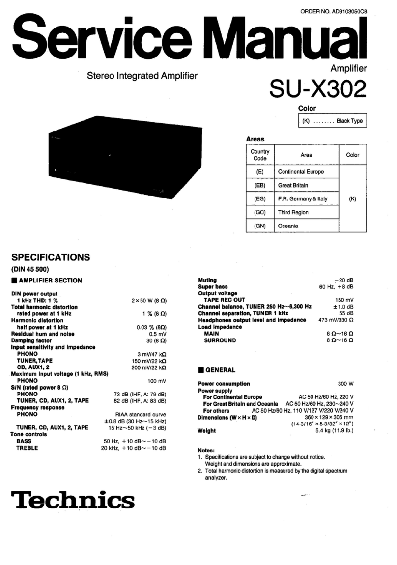
Technics SU-X302 User manual

Technics

Technics SU-X302 User manual

Technics SU-V85A - service User manual

Technics

Technics SU-V85A - service User manual

Technics SE-A5 User manual

Technics

Technics SE-A5 User manual

Technics SU-V6X - service User manual

Technics

Technics SU-V6X - service User manual

Technics SE-A1000 User manual

Technics

Technics SE-A1000 User manual

Technics ST-3150 User manual

Technics

Technics ST-3150 User manual

Technics SU-X901 - service User manual

Technics

Technics SU-X901 - service User manual

Technics SU-G30 User manual

Technics

Technics SU-G30 User manual

Technics SA-EH770 User manual

Technics

Technics SA-EH770 User manual

Technics SU-V4X User manual

Technics

Technics SU-V4X User manual

Technics SU-700 User manual

Technics

Technics SU-700 User manual

Technics SU-X920DE User manual

Technics

Technics SU-X920DE User manual

Technics SU-VX620 - service User manual

Technics

Technics SU-VX620 - service User manual

Technics SE-HD81 User manual

Technics

Technics SE-HD81 User manual

Technics SE-A900S User manual

Technics

Technics SE-A900S User manual
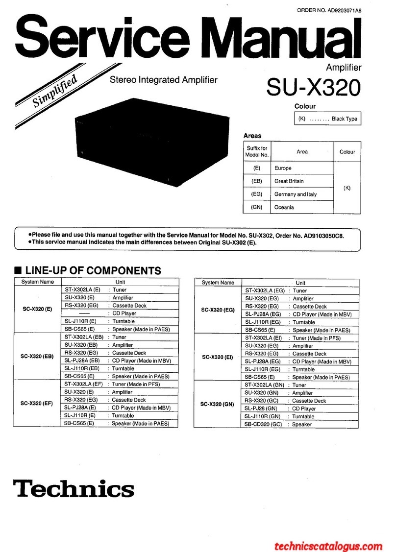
Technics SA-EH750 User manual

Technics

Technics SA-EH750 User manual

Technics SU-V7 User manual

Technics

Technics SU-V7 User manual

Technics SE-CH610 User manual

Technics

Technics SE-CH610 User manual

Technics SU-VX620 - service User manual

Technics

Technics SU-VX620 - service User manual

Technics SA-EH560 User manual

Technics

Technics SA-EH560 User manual

Technics SU-C800U User manual

Technics

Technics SU-C800U User manual
Technics SUV-500 User manual

Technics

Technics SUV-500 User manual

Technics SU-7300 - service User manual

Technics

Technics SU-7300 - service User manual

Technics SU-V5 User manual

Technics

Technics SU-V5 User manual

Popular Amplifier manuals by other brands

Blaupunkt GTA 2600 HP instruction manual

Blaupunkt

Blaupunkt GTA 2600 HP instruction manual

SoundBox Mozart Phono Reference Operation manual

SoundBox

SoundBox Mozart Phono Reference Operation manual

Martin Audio MA2.8 user guide

Martin Audio

Martin Audio MA2.8 user guide

Burmester 808 MK5 owner's manual

Burmester

Burmester 808 MK5 owner's manual

PowerAcoustik STAX-1250/2 owner's manual

PowerAcoustik

PowerAcoustik STAX-1250/2 owner's manual

Camille Bauer SINEAX TV 808-115 operating instructions

Camille Bauer

Camille Bauer SINEAX TV 808-115 operating instructions

Rotel RA-820B owner's manual

Rotel

Rotel RA-820B owner's manual

Rotel RA-712 owner's manual

Rotel

Rotel RA-712 owner's manual

Quicksilver Quicksilver Audio V4 Mono Amplifier operating instructions

Quicksilver

Quicksilver Quicksilver Audio V4 Mono Amplifier operating instructions

Rotel RMB-1075 owner's manual

Rotel

Rotel RMB-1075 owner's manual

Sony TA-H6800E Service manual

Sony

Sony TA-H6800E Service manual

Pyle PAMP1000 user guide

Pyle

Pyle PAMP1000 user guide

JL Audio 300/4v2 owner's manual

JL Audio

JL Audio 300/4v2 owner's manual

Imagine DA-HR6802+DL Installation and operation manual

Imagine

Imagine DA-HR6802+DL Installation and operation manual

Pioneer A-229 operating instructions

Pioneer

Pioneer A-229 operating instructions

Lanzar OPTIHC 3502 owner's manual

Lanzar

Lanzar OPTIHC 3502 owner's manual

ICT ICT180S-12BRC instruction manual

ICT

ICT ICT180S-12BRC instruction manual

Simaudio MOON 860A v2 owner's manual

Simaudio

Simaudio MOON 860A v2 owner's manual

manuals.online logo
manuals.online logoBrands
  • About & Mission
  • Contact us
  • Privacy Policy
  • Terms and Conditions

Copyright 2025 Manuals.Online. All Rights Reserved.