Chargestorm AB CSR100 User manual
Installation Instruction
Revision
A.3
Page (pages)
1(23)
Issued by
Stefan Gabrielsson
Date of creation
2013-01-30
Status
Release
Document No
Pd_IM_0006
Description
Installation and maintenance instruction CSR100
Directory
PLM
Chargestorm AB Article No: 720-00004
1 Introduction
This document shows how to electrically install the Charge Station CSR100.
IMPORTANT
Only certified electricians are allowed to perform the installation described in this
document.
The estimated time for the installation and verification is less than 30 minutes per chargestation.
NOTE
The recommended installation height is 145-160cm from floor to top of the station.

Chargestorm AB Installation and Maintenance Instruction
Document No
Pd_IM_0006
Title
Installation and maintenance instruction CSR100
Revision
A.3
Page(pages)
2(23)
Chargestorm AB
2 Revision history
Issue
Resp
Date
Compatibility / Comments
0.1
SG
2012-03-26
First issue.
0.2
SG
2012-08-09
0.3
SG
2013-01-21
Now with version 2 mechanics
0.4
SG
2013-01-27
Wall mount drafted
A.1
SG
2016-08-31
Migrated to new document management system
A.2
SG
2016-09-14
Updated after internal review
A.3
SG
2016-12-05
Added note that power wires shall be checked during installation
3 Prerequisites
3.1 Tools
Before performing the installation, verify that you have the following tools:
ü Hex key 4 mm or torx key (T18)
ü Hex key 5mm or a long torx key (T25).
ü Hex key 3 mm or torx key (T15)
ü Hex key 6 mm or torx key (T40)
ü Flat head screw driver, head 3mm
ü Flat head screw driver, head 6mm
ü Philips screw driver
ü Multimeter
ü Ruler
ü Peeling plier
For wall mounting kit
ü Screw kit (3 screws ) for wall mounting
ü Drill
For software programming
ü Laptop with terminal application installed
ü USB cable, extension cord with miniUSB type
B connector for connecting to the CCU (and
USB type A connector for connecting to the
Laptop), see Figure 1.
ü USB flash drive
Figure 1 USB cable needed for installation
3.1 Electrical wiring
Before performing installation of the charge station, verify the following:
Chargestorm AB Installation and Maintenance Instruction
Document No
Pd_IM_0006
Title
Installation and maintenance instruction CSR100
Revision
A.3
Page(pages)
3(23)
Chargestorm AB
ü Electrical wiring at installation site is dimensioned according to charge station specification
ü Secure that the power is turned off during installation
ü During installation, verify that the power wires to circuit breaking, relay and power terminals are
securely connected.
3.2 Charge Portal configuration
The Charge Portal is preferably updated with the information for the charge stations to install before
performing the installation on site. The charge station is identified by the Charge Portal via the Chargebox
ID. The ChargeboxID must be configured identical in both system. For more information on how to
configure the Charge Portal, see the Charge Portal User manual (Article number Pd_UM_0003).
4 Preparation
The following items should be prepared before starting the installation:
• Electrical schematics shall be available for the installation site
If the communication to the portal shall be set up during the installation must the following be prepared
(This is most often handled by a Chargestorm representative):
• Software Portal Configuration
o Create logical charge stations under correct site in portal and allocate chargeboxid for each
station
• Internet access
o If using GPRS/3G for internet access the SIM card must be mounted in the Charge Station.
This is preferably done during final assembly and it is encouraged that the SIM card is sent
to your contact person at Chargestorm in time.
o If using Ethernet for internet access the Ethernet wiring must be in place. Further, IP
address of the gateway and name server must be known as well as the IP address to use for
the Charge Station.
• Authentication
o If RFID is supposed to be used for user authentication make sure that RFID tags are
available for testing
5 Abbreviations
CCU Charge Communication Unit. The micro controller board in a Charge
Station or grid communication unit runnning the communication
applications.
GCU Grid Communication Unit. Handles communication with several slave
Charge Stations and the Charge Portal. Contains logic to prevent power
overload in the local grid.
RFID Radio Frequency Identification
USB Universal Serial Bus

Chargestorm AB Installation and Maintenance Instruction
Document No
Pd_IM_0006
Title
Installation and maintenance instruction CSR100
Revision
A.3
Page(pages)
4(23)
Chargestorm AB
6 Charge Station models
See CSR100 for a list and description of CSR100 models. It is important to know which model that is to
be installed.
7 Main installation flow
There are three different recommended installation flows depending on whether the installation is of
master Charge Stations, slave Charge Stations or unmanaged Charge Stations.
• Master Charge Station – A master Charge Station is a stand alone Charge Station and can thus
be installed without any dependencies on other components.
• Slave Charge Station – For slave Charge Station installation shall the Master charge station or
Grid Communication Unit be installed first since it is not possible to perform the final installation
test until internet access is available via the Master or Grid Communication Unit.
• Unmanaged Charge Station – Charge Stations that have no internet access. Programmed via
command line interface during installation. Unmanaged Charge Stations are not described further
in this document. Unmanaged Charge Stations are always delivered with a default configuration
that allows anyone to charge without RFID authentification. Installing unmanaged Charge
Stations is simply a matter of mounting housing and connecting power.
8 Mounting types
There are two different ways of mounting the Charge Station:
• Wall mounted
• Pole mounted
9 Pole mounted installation
The diagram below illustrates the major steps needed to perform an installation.
Prepare&Charge&
Portal
Install&Master&
Charge&Station(s)
Perform&final&
installation&test&of&&
Charge&Station(s)
Prepare&Charge&
Portal
Install&&Master&
Grid&Com.&Unit
Install&Slave&
Charge&
Station(s)
Perform&final&
installation&test&
of&&Charge&
Station
Chargestorm AB Installation and Maintenance Instruction
Document No
Pd_IM_0006
Title
Installation and maintenance instruction CSR100
Revision
A.3
Page(pages)
5(23)
Chargestorm AB
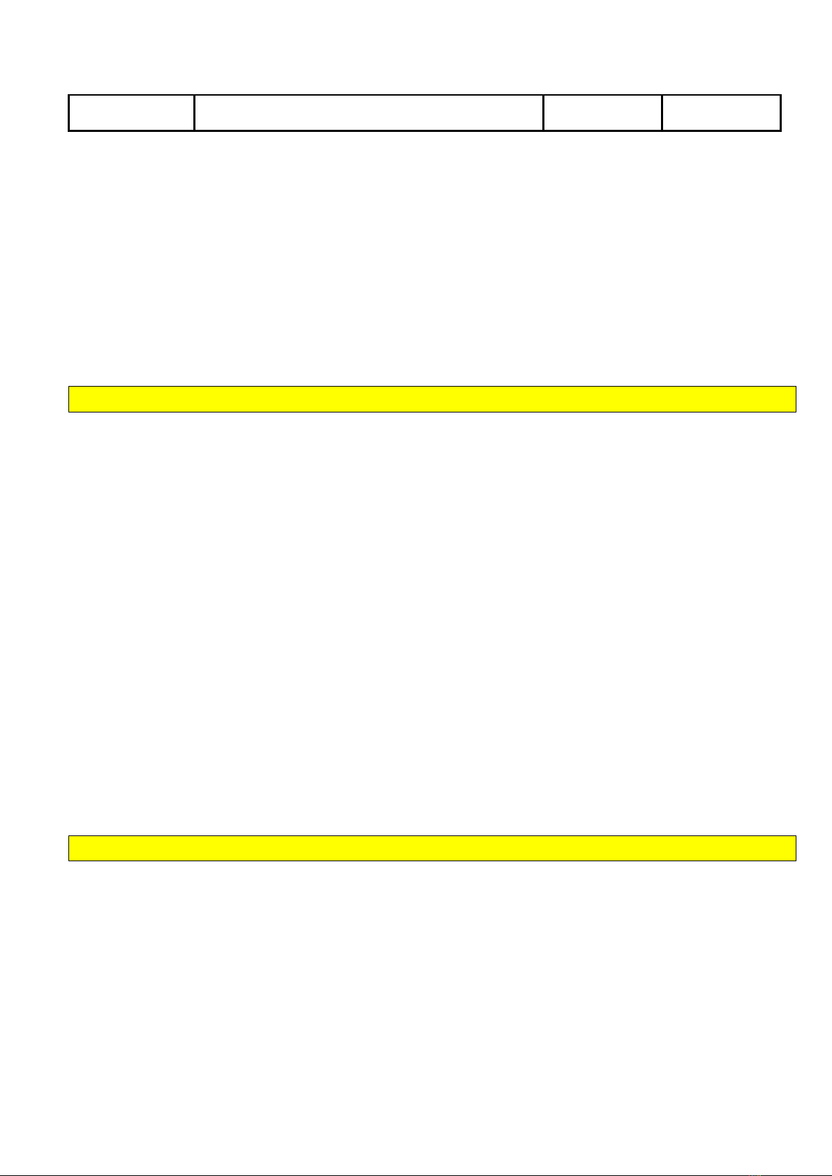
Figure 2 Example of pole mount installation
9.1 Prepare wires
Objective:
In this step are the power wires, phases (L1-3), neutral (N) and protective earth (PE) from the pole
prepared to be ready for attaching in the charge station.
Step by step:
1. At least 20 cm of wires must be available above the top of the pole
2. Peel the wires 14 mm.
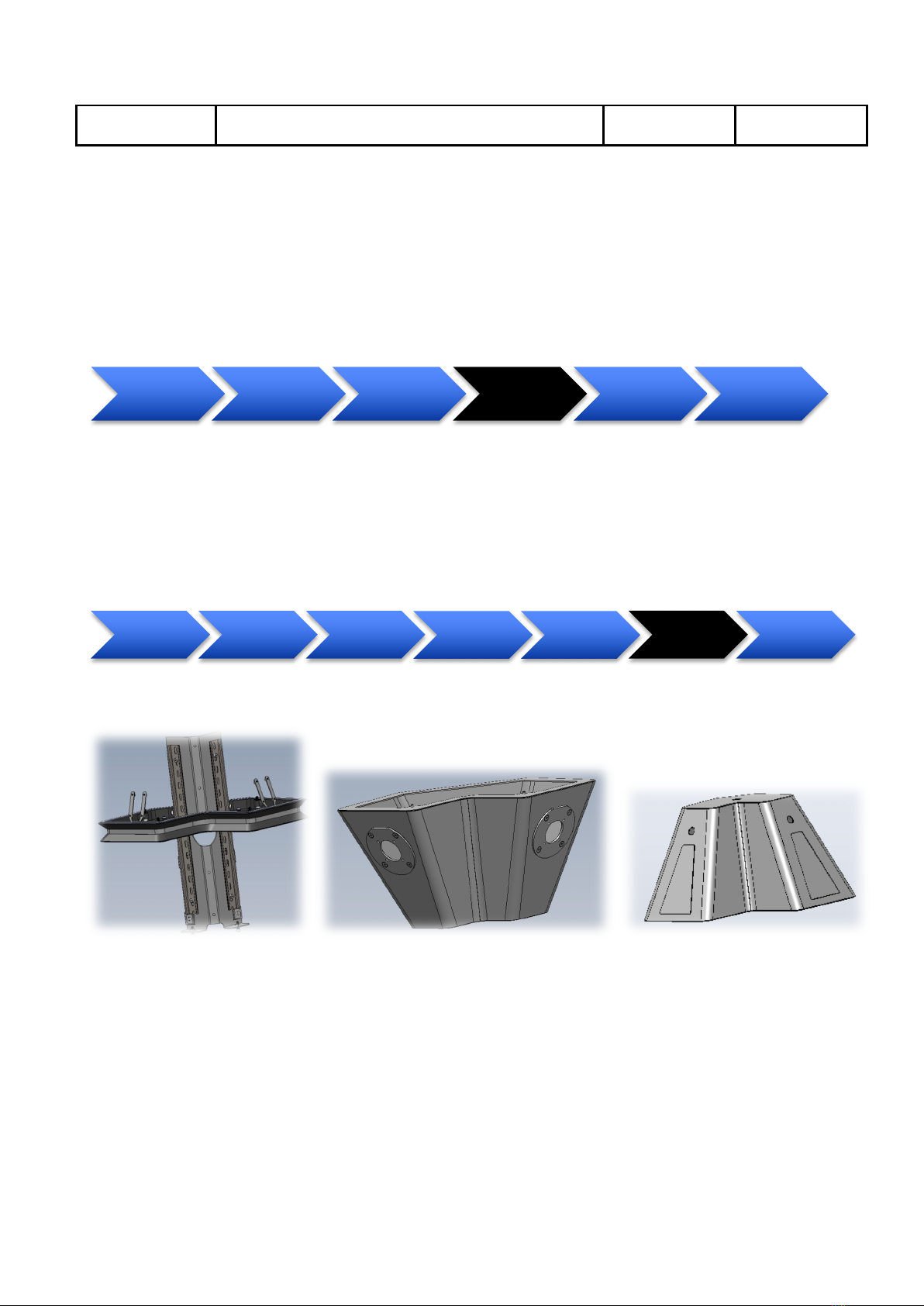
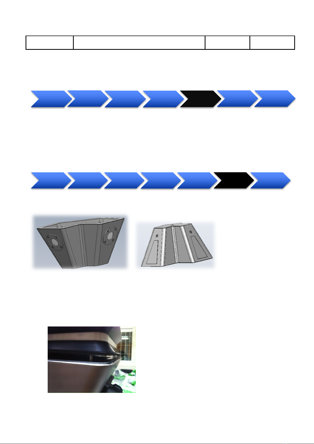
9.2 Disassemble Charge Station
Objective:
In this step is the Charge Station bottom and top cover dismounted.
prepare&wires Disassemble&
Charge&Station&
Mount&&
bottom&cover&
and&frame&on&
pole
Software&
configuration
Mount&&top&
cover Final&test
Prepare&wires
Disassemble&
Charge&
Station&
Mount&frame&
on&pole
Software&
Configuration Mount&covers Final&test

Chargestorm AB Installation and Maintenance Instruction
Document No
Pd_IM_0006
Title
Installation and maintenance instruction CSR100
Revision
A.3
Page(pages)
6(23)
Chargestorm AB
Parts:
Mounting frame(431-00011) Bottom cover (431-00023) Top cover (431-00030)
Step by step:
1. Unpack the chargestation from the packaging carbon box.
2. Unscrew the two screws in the bottom cover.
3. Pull the bottom cover downwards and disconnect the internal cables so that the bottom cover can
be removed.
Connect&wires
Disassemble&
Charge&
Station&
Mount&frame&
on&pole
Software&
Configuration Mount&covers Final&test
Chargestorm AB Installation and Maintenance Instruction
Document No
Pd_IM_0006
Title
Installation and maintenance instruction CSR100
Revision
A.3
Page(pages)
7(23)
Chargestorm AB
4. Unscrew the four screws in the mounting frame attaching the top cover with the frame.
5. Disconnect eventual antenna cable connecting top cover with frame and remove the top cover
6. DONE
9.3 Mount frame on pole
Objective:
In this step the mount frame attached to the pole. Make sure that external power is off before connecting
power to the charge station. Thereafter is the fuse and ground fault function tested.
Parts: Same as in previous step
Step by step:
1. Gently put the bottom cover on the pole.
2. Put the mounting frame on the pole and tighten the four screws squeezing the frame to the pole
Connect&
wires
Disassemble&
Charge&
Station&
Mount&frame&
on&pole
Software&
Configuration Mount&covers Final&test

Chargestorm AB Installation and Maintenance Instruction
Document No
Pd_IM_0006
Title
Installation and maintenance instruction CSR100
Revision
A.3
Page(pages)
8(23)
Chargestorm AB
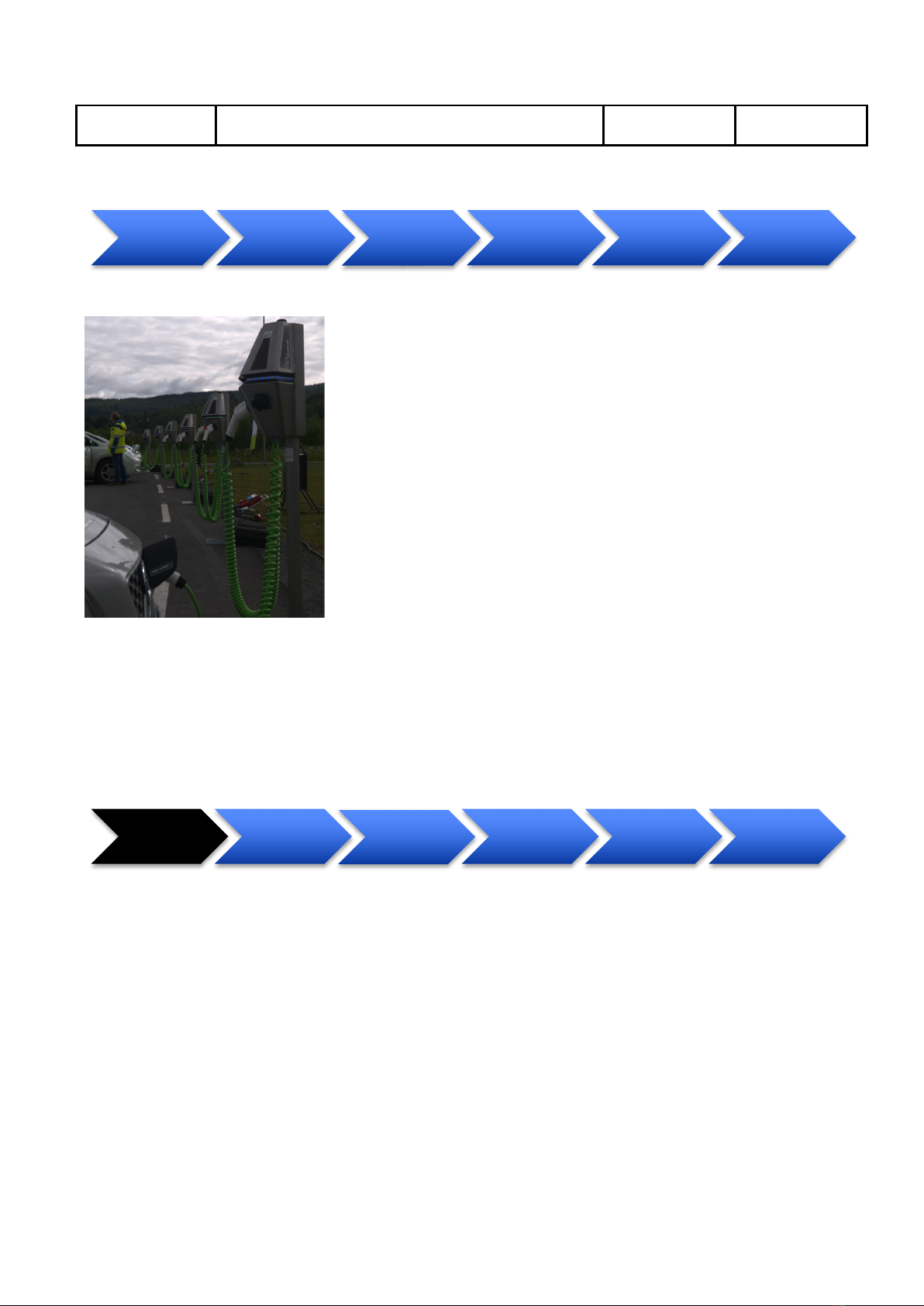
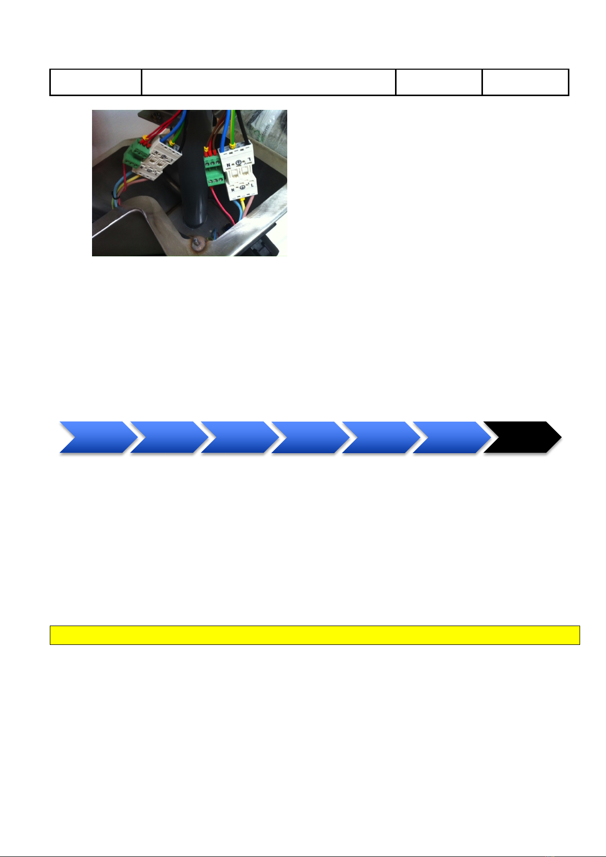
3. Check that the internal power (L1-3) wire (coming from the pole) is matching the electrical
drawings for the installation.
4. Attach the power wires to the terminal block on the mounting plate.
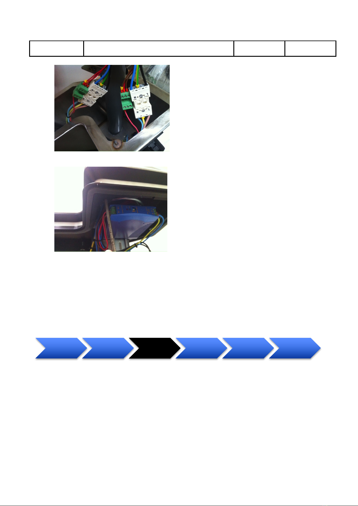
5. Attach the Ethernet cable to the CCU board (if applicable)
6. Check that the ground fault detector and the fuse are on.
7. Enable external AC power and let the internal CCU boot up (LED strip turns green after less than
30 seconds.)
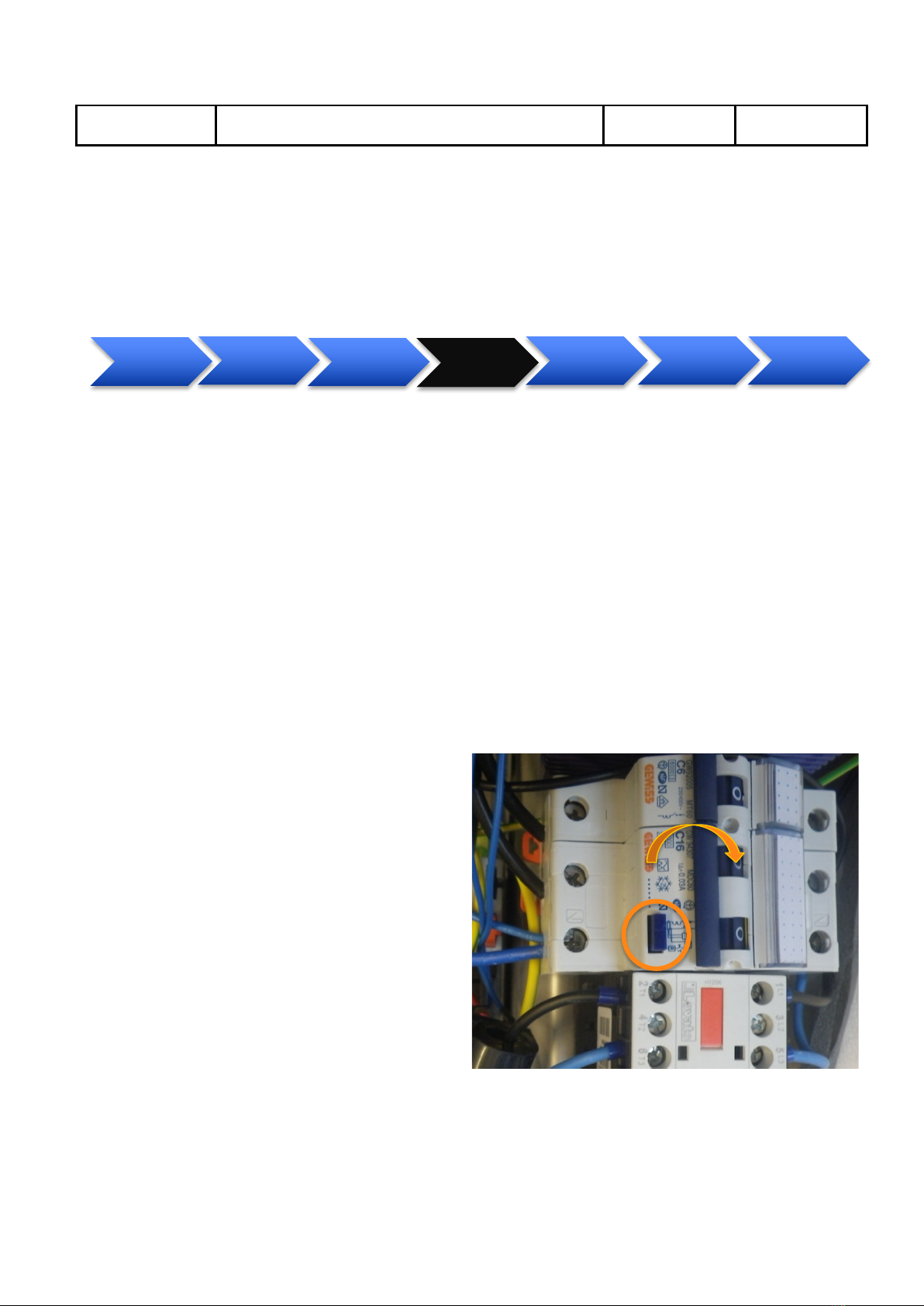
8. Push the ground fault test button
9. For each ground fault unit (one per
outlet). Verify that the LED strip turns
red. There after push the reset by flipping
the toggle switch (see Fel! Det går inrte
att hitta någon referenskälla.) and
verify that the LED strip turns green
Figure 3 Ground fault unit, with the test button and the
action to reset it using the toggle switch marked.
Chargestorm AB Installation and Maintenance Instruction
Document No
Pd_IM_0006
Title
Installation and maintenance instruction CSR100
Revision
A.3
Page(pages)
9(23)
Chargestorm AB
9.4 Software Configuration
The software configuration step is only necessary to perform in case configuration on the CCU must be
changed in order to establish connection to the Charge Portal. The CSR100 is always delivered with a
default configuration that makes it work in stand alone mode. Often is a Chargestorm representative
responsible for configuring the internet access. For more information about software configuration see
chapter 11.
9.5 Mount covers
Objective:
In this step is the top and bottom cover attached to the frame.
Parts:
Mounting frame(431-00011) Bottom cover (431-00023) Top cover (431-00030)
Step by step:
1. Re-attach the antenna cable (if any) and put back the top cover. Make sure the top cover fits the
guiding screws and then fasten the four screws.
Connect&
wires
Disassemble&
Charge&
Station&
Mount&frame&
on&pole
Software&
configuration Mount&covers Final&test
Mount&wall&
plate Connect&wires
Disassemble&
Charge&
Station&
Mount&frame Software&
configuration Mount&covers Final&test

Chargestorm AB Installation and Maintenance Instruction
Document No
Pd_IM_0006
Title
Installation and maintenance instruction CSR100
Revision
A.3
Page(pages)
10(23)
Chargestorm AB
2. Lift the bottom cover up to the mounting frame. Reconnect the internal cables on the way.
3. Finally tighten the screws in the bottom.
9.6 Final test
Objective:
In this step is the functionality of the Charge Station verified.
Parts: -
Step by step:
1. Document in the installation log (Pd_CL_0001) the outcome of the ground fault tests.
2. Check that the mounting looks solid and that there are no external damage on the Charge Station.
Document result in installation log (Pd_CL_0001).
3. If an electrical vehicle is available test charging on all outlets. Document result in installation log
(Pd_CL_0001).
4. Optionally, document the GPS coordinates of the installation and update the Charge Portal with
that information for each Charge Station.
Mount&wall&
plate Connect&wires
Disassemble&
Charge&
Station&
Mount&frame Software&
configuration
Mount&bottom&
cover Final&test

Chargestorm AB Installation and Maintenance Instruction
Document No
Pd_IM_0006
Title
Installation and maintenance instruction CSR100
Revision
A.3
Page(pages)
11(23)
Chargestorm AB
10 Wall mounted installation
The diagram below illustrates the major steps needed to perform a wall mount installation.
Figure 4 Example of wall mounted installation
10.1 Disassemble Charge Station
Objective:
In this step the Charge Station covers dismounted. See chapter 9.2 for instruction.
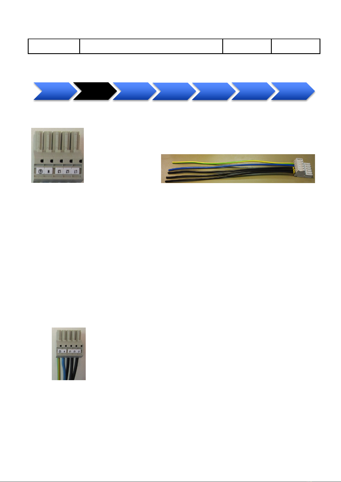
10.2 Prepare wires
Objective:
In this step, the power wires, phases (L1-3), neutral (N) and protective earth (PE) are connected to the
power socket. The power socket is later attached to matching connector in the Charge Station.
Disassemble&
Charge&Station& Prepare&wires Mount&wall&
plate& Mount&frame Software&
configuration Mount&cover Final&test
Dissassemble&
Charges&
Station
Prepare&wires Mount&wall&
plate& Mount&frame Software&
configuration Mount&&covers Final&test
Chargestorm AB Installation and Maintenance Instruction
Document No
Pd_IM_0006
Title
Installation and maintenance instruction CSR100
Revision
A.3
Page(pages)
12(23)
Chargestorm AB
Parts:Power Socket Connector, Internal power wire, Peeling Plier
Figure 5 Power Socket Connector (Art No 125-00013), internal power wire power wire (840-00005)
Step by step:
1. For incoming power: Peel the wires 14 mm. Note that the cable/wire diameter supported by the
socket is 0.5-6mm2.
2. Push the peeled protective earth (PE) wire into the matching position in the socket until it snaps
into place.
a. Test that the wire is fastened by gently pulling it backwards.
3. Push the peeled neural (N) wire into the matching position in the socket until it snaps into place.
a. Test that the wire is fastened by gently pulling it backwards.
4. Push the peeled phases (L1-3) wires into the matching positions in the socket until they snap into
place.
a. Test that the wires are fastened by gently pulling it backwards.
5. If the installation uses Ethernet for communication connect a female Ethernet plug.
Figure 6 Power Socket Connector when connected to incoming wires
6. Connect the power wire (840-00005) that comes with the Charge station to the terminal block on
the mounting frame. Note that the cable must be inserted in the frame whole (in the LED list) on
the back side before the wires are attached to the terminal block.
Disassemble&
Charge&
Station&
Prepare&wires Mount&wall&
plate Mount&frame Software&
configuration Mount&overs Final&test

Chargestorm AB Installation and Maintenance Instruction
Document No
Pd_IM_0006
Title
Installation and maintenance instruction CSR100
Revision
A.3
Page(pages)
13(23)
Chargestorm AB
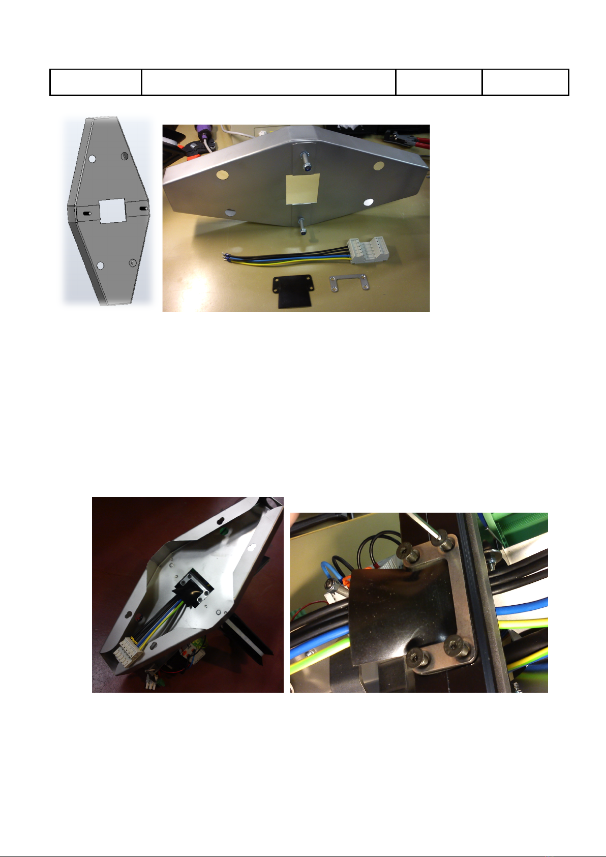
10.3 Mount wall plate
Objective:
In this step, is the mounting frame attached to the wall plate and there after is the wall plate
attached to the wall.
Parts: 4 mm Hex key and 1 or 2 hex socket screws (M5, 16 mm long, and 4 mm socket size) for securing
the frame and the following main components
Mounting frame(431-00011) Bottom cover (431-00023) Top cover (431-00030)
Mount&wall&
plate
Prepare&wires
Dissaassemble&
Charge&&
Station
Connect&
cables
Software&
configuration Mount&covers Final&test
Chargestorm AB Installation and Maintenance Instruction
Document No
Pd_IM_0006
Title
Installation and maintenance instruction CSR100
Revision
A.3
Page(pages)
14(23)
Chargestorm AB
Wall mounting plate(431-00036), power connector with wire
Step by step:
1. Identify the location on the wall where the Charge Station is to be mounted:
a. Make sure the power cables and possible Ethernet cable is available just under or above
the wall plate. It is also possible to connect the power wiring from behind. Note that a
gasket must be used to make the unit waterproof.
2. Drill four screw holes for the wall plate
3. Slide the mounting frame on the on the two guiding screws on the wall mounting kit while the
cables are inserted throught frame hole. Fastened the mounting frame with the two nuts.
4. Fasten the gasket with help of the metal frame and four screws
Chargestorm AB Installation and Maintenance Instruction
Document No
Pd_IM_0006
Title
Installation and maintenance instruction CSR100
Revision
A.3
Page(pages)
15(23)
Chargestorm AB
10.4 Connect Cables
Objective:
In this step is the power cables connected, ethernet cable optionally connected and ground fault tested.
Parts: -
Step by step:
1. Make sure external power is off.
2. Check that the internal power (L1-3) wire is matching the electrical drawings for the installation.
3. Attach the external and internal power connectors to each other.
4. Attach the Ethernet cable (if applicable)
5. Fasten the wall plate with four screws (the screws are not included).
6. Check that the ground fault detector and the fuse are on.
7. Enable external AC power and let the internal CCU boot up (LED strip turns green after less than
30 seconds.)
8. Push the ground fault test button
9. For each ground fault unit (one per
outlet). Verify that the LED strip turns
red. There after push the reset by flipping
the toggle switch (see Fel! Det går inrte
att hitta någon referenskälla.) and
verify that the LED strip turns green
10.5 Software Configuration
The software configuration step is only necessary to perform in case configuration on the CCU must be
changed in order to establish connection to the Charge Portal. The CSR100 is always delivered with a
default configuration that makes it work in stand alone mode. Often is a Chargestorm representative
Connect&
cables
Prepare&wires
Dissaassemble&
Charge&&
Station
Mount&&wall&
plate
Software&
configuration Mount&covers& Final&test
Figure 7 Ground fault unit, with the test button and the
action to reset it using the toggle switch marked.
Chargestorm AB Installation and Maintenance Instruction
Document No
Pd_IM_0006
Title
Installation and maintenance instruction CSR100
Revision
A.3
Page(pages)
16(23)
Chargestorm AB
responsible for configuring the internet access. For more information about software configuration see
chapter 11.
10.6 Mount covers
Objective:
In this step is the bottom cover attached to the frame and some ground fault and fuse tests performed.
Parts: 4 mm Hex key
Bottom cover (431-00023) Top cover (431-00030)
Step by step:
1. Re-attach the antenna cable (if any) and put back the top cover. Make sure the top cover fits the
guiding screws and then fasten the four screws.
2. Lift the bottom cover up to the mounting frame.
Software&
Configuration
Prepare&wires
Dissaassemble&
Charge&&
Station
Mount&&wall&
plate
Connect&
cables Mount&covers Final&test
Mount&wall&
plate Connect&wires
Disassemble&
Charge&
Station&
Mount&frame Software&
configuration Mount&covers Final&test
Chargestorm AB Installation and Maintenance Instruction
Document No
Pd_IM_0006
Title
Installation and maintenance instruction CSR100
Revision
A.3
Page(pages)
17(23)
Chargestorm AB
3. Finally tighten the two screws in the bottom.
10.7 Final test
Objective:
In this step the functionality of the Charge Station is verified.
Parts: - checklist
Step by step:
1. Document in the installation log (Pd_CL_0001) the outcome of the ground fault tests.
2. Check that the mounting looks solid and that there are no external damage on the Charge Station.
Document result in installation log (Pd_CL_0001).
3. If an electrical vehicle is available test charging on all outlets. Document result in installation log
(Pd_CL_0001).
4. Optionally, document the GPS coordinates of the installation and update the Charge Portal with
that information for each Charge Station
11 Software Configuration
The software configuration step is only necessary to perform in case configuration on the CCU must be
changed in order to establish connection to the Charge Portal. The CSR100 is always delivered with a
default configuration that makes it work in stand alone mode. Often is a Chargestorm representative
responsible for configuring the internet access.
Objective:
In this step is the Charge Station configuration information copied from the Charge portal to the flash in
the Charge Station. A communication test to the Charge Portal is also part of this step
Mount&wall&
plate Connect&wires
Disassemble&
Charge&
Station&
Mount&frame Software&
configuration
Mount&bottom&
cover Final&test

Chargestorm AB Installation and Maintenance Instruction
Document No
Pd_IM_0006
Title
Installation and maintenance instruction CSR100
Revision
A.3
Page(pages)
18(23)
Chargestorm AB
Pre-requisites:
Before starting the software configuration should the Charge Portal be configured and a mini USB cable
be available in order to connect to the CCU from the lap top.
Parts: USB cable, see Figure 1., USB flash drive, and laptop with terminal software.
Step by step:
1. Boot up Charge Station (external power must be enabled)
2. Attach the USB cable to your laptop and the Charge Station
Figure 8 USB cable connected to the Charge Station CCU (and marked) in the image to the left, and USB flash drive
inserted in the image to the right (To the left is an ethernet cable connected).
3. Follow the CCU configuration manual (Pd_CM_002).
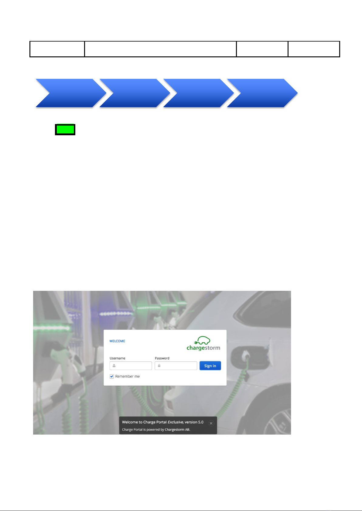
12 Charge Portal
The Charge Portal is a web portal providing access to the Charge Stations owned by the operator, over the
Internet. The portal shows usage and alarms of the Charge Stations and is also used for configuration of
the Charge Stations.
The diagram below illustrates the major steps that needs to performed in the Charge Portal before an
installation.
Charge&station&
dissassembled
Software&
configuration
Assemle&
Charge&Station
Chargestorm AB Installation and Maintenance Instruction
Document No
Pd_IM_0006
Title
Installation and maintenance instruction CSR100
Revision
A.3
Page(pages)
19(23)
Chargestorm AB
NOTE
For unmanaged Charge Stations, i.e. stations that do not have any Internet access via Ethernet or
3G is no configuration in the Charge Portal needed.
Internet access
Our Charge Stations are equipped with an Ethernet interface and optionally a 3G/GPRS modem.
Ethernet interface
Customers using Ethernet to access the web portal must assign static IP addresses to Master Charge
Stations and Grid Communication Units. The IP address can be either public or private (sitting behind a
firewall). The importance is that Charge Stations have access to the Charge Portal URL, which is unique
per customer. The traffic is only web based and is using the http or https ports depending on
configuration.
3G/GPRS
In order to use 3G/GPRS as carrier, the customer is requested to purchase the SIM-cards that are to be
mounted in the Charge Station. It is very much preferred that the SIM-cards are sent to Chargestorm
before final assembly since it simplifies the installation. Configuration parameters required to establish
IP communication from the modem must be provided by our customer (who in turn should ask the
wireless operator/provider of SIM cards for that information).
Figure 9 Example of the log in page for the Charge Portal
Request&
portal&log&in&
parameters
Create&Site Add&Charge&
Stations Final&test
Chargestorm AB Installation and Maintenance Instruction
Document No
Pd_IM_0006
Title
Installation and maintenance instruction CSR100
Revision
A.3
Page(pages)
20(23)
Chargestorm AB
12.1 Request portal log in parameters
Objective:
The first time a new customer purchases Charge Stations from Chargestorm, a customer unique portal is
created. The portal can be accessed from any modern web browser with Internet access.
In order to log in to the portal the following parameters must be retrieved:
• URL – the web address of the portal
• User name – an email address used to log in to the portal
• Password – a password needed to log in to the portal
NOTE
It is only the first time you order Charge Stations that you need to request the portal log in
parameters.
Pre-requisites:
There are different levels of customization of the Charge Portal that can be arranged based on different
customer needs, such as coloring schemes, logotypes etcetera. Therefore, check your specific contract so
that you are aware of what is included in your service.
Step by step:
1. Contact your sales person and ask for portal log in parameters.
2. The sales person will generate an email containing:
a. URL to portal typically in format http://<companyname>.oamportal.com
b. Email address and password for administrator account
3. Log in to the portal with the information in step 2. A log in page similar to the figure below should
be shown in the web browser.
Request&
portal&log&in&
parameters
Create&Site Add&Charge&
Stations Final&test
Other manuals for CSR100
1
Table of contents


