Dension WiRC User manual
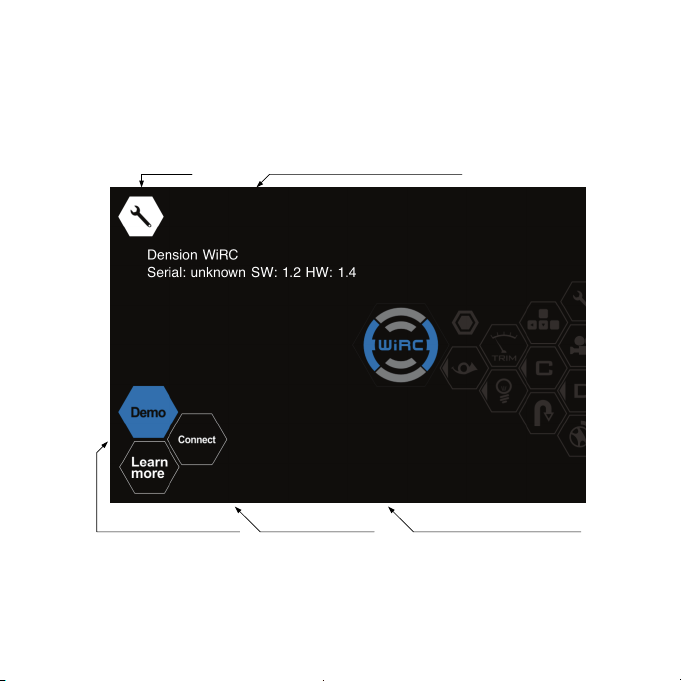
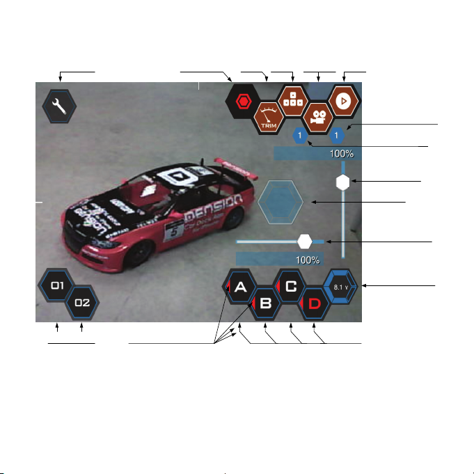
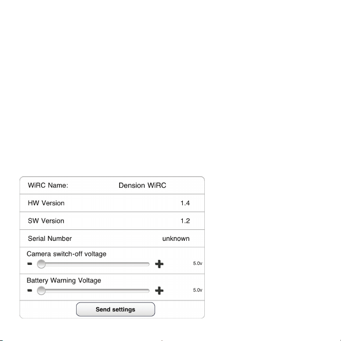
WRC-9201-1
Users Manual
V2.0
For news check regularly wirc.dension.com

2
Disclaimer
Please read and fully understand this manual before installing and operating
WiRC. Everyone should use WiRC on their own responsibility.
Children under 12 years should use WiRC with adult supervision.
Improper use of models may cause injuries or property damage, so please
always drive with extreme caution. Never use models on public roads, crowded
areas, near small children or animals.
Take extreme care when connecting electrical components. Do not use cables
with damaged connectors or insulation and take care of correct polarity.
Incorrect electrical connections may cause short circuit or even fire.
Models have moving and rotating parts and some components may get hot
after use. To avoid injuries, do not touch these parts!
Incorrect setup of failsafe functions and too low battery voltage may cause the
loss of control on model, and may cause damages.
Read and understand the manual of other components (incl. batteries,
chargers, etc) connected to WiRC. Use only such components that fit the WiRC
technical specifications.
Other WiFi networks or strong electromagnetic fields may affect the
performance of WiRC! By using WiRC consider applicable local regulations on
personality rights and data protection laws.
WiRC has 12 month full warranty, which covers defects caused by
defective parts or workmanship.
Warranty does not cover defects, damages or injuries due to improper
installation, regardless use of WiRC driven models, or any problems caused by
other parts in model.
Dension reserves right to change the product, it's components or contents of
this manual, without any prior notice!

3
1Installation and setup
1.1 Package content
WiRC module
USB Camera
USB WiFi stick
Power T-cable (Tamiya connector)
1.2 System overview
POWER
-
+
B
WiRC
CH1
CH2
CH3
CH4
CH5
CH6
CH7
CH8
Speaker
Mic
MOTOR
ESC
/
BEC
6V - 16V
B
A
T
T
E
R
Y
ON
OFF
T- CABLE
. . .
CH 4-8
Digital In 1..4
CH3
SERVO
CH2
SERVO
Rx/Tx Ext
-
B S
Digital Out 1..4
+
I2C Ext
1
2
3
4
CH1
WiFi
C
A
M

4
1.3 Positioning and fixing parts
Camera:
◦Mount on a stable base, which doesn't move or resonate
◦The camera should have a free sight, with no parts in front
of the lens
◦Do not place the camera in a position where it can be
damaged when the model hits an obstacle
◦Secure the plastic clip of the camera with included cable tie
WiFi dongle
◦Position it on the top part of the model
◦Place it as far away from metal parts as possible
◦Fasten the USB connector with included cable tie
WiRC module:
◦Use the place of the original receiver, if possible
◦Make sure that cables (Camera, WiFi, Power, Servos, ESC)
can run and connect to the module smoothly
◦Fix WiRC with included double-sided adhesive tape
Before starting installation, disconnect all the
battery, servo, ESC cables and remove the original
receiver – if any.
WiRC is not waterproof. Water and humidity can
cause damage to WiRC, for which we assume no
liability.

5
1.4 Connecting the cables
1. Connect the camera cable to one of the USB ports on the
WiRC module (You can select any of the two ports)
2. Connect the WiFi dongle to the other USB port
3. Connect the Servo / ESC cables to the WiRC module.
Note the default channel layout as below:
4. Connect the power cable to the WiRC module
5. Secure any loose cables
6. Connect the Power cable to the battery and the ESC
1.5 Powering WiRC
Usually, an RC receiver is powered by the ESC (Electronic Speed
Control) or by a standalone BEC (Battery Eliminator Circuit).
WiRC however has higher power consumption and a minimum
input voltage requirement of 5.5V, that many BECs or ESCs
cannot provide.
Therefore WiRC has to be connected
directly to the battery, by using the
included T-cable.
(see also system diagram on page 3)
WiRC does not have its own on/off
switch.
Channel Function
Ch-1 Steering servo
Ch-2 Speed control
CH1
CH2
CH3
CH4
CH5
CH6
CH7
CH8
POWER CONNECTOR
-
+
B
-
B S
WiRC
BATTERY
BATTERY
POWER_ENABLE

6
POWER
-
+
B
WiRC
CH1
CH2
CH3
CH4
CH5
CH6
CH7
CH8
. . .
CH 3-7
CH1
SERVO
CH2
SERVO
-
B S
CH8
WiFi
C
A
M
6 - 16 V
4.8 - 6 V
B
A
T
T
E
R
Y
2
B
A
T
T
E
R
Y
1
ON
OFF
Instead, it powers on by applying voltage to one of the servo
channels or the POWER_ENABLE pin of the Power Connector.
This ensures that WiRC is always powered on and off together
with the other electrical components of the model.
Please note, that WiRC does not supply power to the servos, the
Ch1-8 connectors only distribute external power coming from
BEC, ESC or additional battery.
If your RC model has no BEC or ESC, then connect WiRC directly
to the Battery_1 to provide the necessary power to WiRC and use
an additional Battery_2 with switched cable for servos.
WiRC has an
operating
voltage of
5.5–16V
Servos
normally
operate on
4.8-6V.
Please check
servo
specification
before built
in!

7
2WiRC smartphone Application
To operate your WiRC based model, you need a smartphone
Application.
Smartphone compatibility and links to Application can be found
on wirc.dension.com
2.1 Connecting your smartphone
1. Power up your model
2. Wait for about 5 sec, until WiRC initializes
3. By default WiRC acts as a WiFi hotspot (router), that other
devices can connect to. In the WiFi setup menu of your
smartphone, connect to the “Dension WiRC” network.
4. Launch the WiRC application. You will see the Start screen.
5. Connect to the WiRC device
6. If you have successfully installed WiRC, you should see
control screen and the video stream running in the
background
7. Press Start button on control screen to enable joysticks and
other controls
Before proceeding with configuration, secure your
model on a stand, so that the servos/motors can
move, but the model itself cannot.

8
2.2 Start Screen
Settings List of available WiRC devices
Demo control screen wirc.dension.com Connect to selected WiRC

9
2.3 Control Screen
Settings Video Rec Mode StartCamera
Current Camera
Current Mode
Vertical Axis
Dual Rate
Trim
Joystick
Battery Voltage
Maneuvers Digital Input Status Buttons
Horizontal Axis
Dual Rate
Start button:
The control can be enabled/disabled by pressing the start button.
If the control is disabled, then trim values set on all channels and
joysticks, buttons, etc do not have effect.

10
Trim button:
When this button is pressed then trim values of the channels can
be adjusted with the vertical and horizontal sliders (normally
these sliders set the dual rate. Dual rate settings change both
minimum and maximum outputs on a given channel).
The trim settings can be also changed from the settings menu.
Mode switch button:
Four different modes can be configured in the settings menu. You
can assign the user inputs (joysticks etc.) to the channels and
digital outputs differently in different modes.
You can change the current mode by pressing the mode switch
button.
The number of the current mode is displayed below the button.
Camera switch button:
If there is more than one camera connected to the WiRC. You can
switch camera stream source by pressing the camera switch
button.
The ID of the currently selected camera is displayed on the right
side of the button.
2.4 Settings Menu
For configuration and settings you need to connect to WiRC, start
the application, and select “Settings” icon on the top left corner of
the screen.

11
2.4.1 Basic Settings
You can access the Settings menu with the Settings icon on the
top left corner of the screen. Here you can set:
Transmitter name
The name of the transmitter. By default, this is the name of your
smartphone
Transmitter priority
Defines the priority of your transmitter for multi-driver scenarios.
Changes will effect only new connections.
2.4.2 Channel settings
For each channel being used do following settings:
Channel 1-8

12
Channel name:
Name the channels to remember its function e.g. Steering,
Speed, etc.
Reverse:
Changes the direction of the servo rotation in relation to the
joystick movement.
Test settings button:
Use this button to test Min/Max/Trim settings, when you are
connected to the WiRC. While pressed, the Trim value will be
output for the channel. Once you set Min/Max, their last value will
be output. This allows the quick setup of the three parameters.
Min/Max:
Set the Min/Max value to the desired servo movement or ESC
speed. Max corresponds to the Up or Right position of a joystick
or the maximum speed, while Min corresponds to the Down or
Left position, and the maximum reverse speed.
Trimming:
Sets the center position of a servo, or the idle state of an ESC
Failsafe:
Select the link-loss failsafe action for the channel:
Disable output:
Disable the output of the
channel, so that other failsafe
mechanisms can take over
Last good: WiRC continues to output the last received value

13
Pre-Set: WiRC will output the value you set with the slider
Sensitivity:
Sets the sensitivity type of the
channel. It can be linear to the
control value, or follow an
exponential curve. Negative value of Exponential Factor means
the sensitivity is higher near the center position and lower near
the end position. Positive Exponential Factor means the sensitivity
is lower near the center position and higher near the end
position.
Sensitivity mix / Value mix:
Mixers allow you to set up dependencies between channel output
values. For example, if you want to reduce the steering sensitivity
at higher speeds, you can set up a Sensitivity mix with a
negative factor between the ESC and servo channels. When the
ESC output value is high, the negative sensitivity mix reduces the
channel output changes for the same steering joystick
movement.
Value mixing enables mixing of output values of channels.
Repeat:
Sets the PPM repeat frequency. It can be set for the pair of
channels: 1-2, 3-4, 5-6. Channels 7-8 have a fixed repeat rate of
50Hz.

14
Digital Output 1 - 4
Invert output:
Inverts the state of the digital output, i.e. 0 is output instead of 1
and vice versa
State On range:
Defines the input value at which the digital output is switched on
Between Min-Max range: On
Outside of Min-Max range: Off
2.4.3 Controls
You can assign a control element (joystick, gyroscope or button)
to each channel or digital output.
Only those joystick axes will be present on the drive screen,
which are configured for at least one channel.
Gyro X: Tilting the smartphone to the left or right
Gyro Z: Tilting the smartphone towards
Mode 1-4: Select one of the Modes to configure
Channels 1-8: Select the control element for the channel
Digital outputs: Select the control element for the digital output
Hold position: The selected joystick axis won't return to its zero
position when released

15
Buttons:
Trigger: The button is only active while being pressed
Toggle: The button is switched on/off at each press
Off / On: The output value for the button in each state
2.4.4 Maneuver
Maneuvers allows you to set up pre-set maneuvers for stunts or
hard to control cases. You can instantly access the 2 maneuvers
from the drive screen.
Override: If switched on, the below value will be output during
the maneuver
Value: Set the channel output value
2.4.5 WiRC menu

16
WiRC name:
You can name your WiRC device (i.e. model) to easily distinguish
between different receivers.
HW, SW version, Serial number:
Information about your WiRC. Make sure to include these in a
support request.
Camera switch-off voltage:
You can set a voltage threshold level, below which the camera is
automatically turned off. Useful if you are trying to save your
device running out of battery.
Battery Warning Voltage:
You can set a voltage threshold level, below which the WiRC
application shows a battery warning on the screen.
Wi-Fi Settings
By default the WiRC works in Access Point (AP) mode (like a
WiFi Hotspot or Router), so that other devices can connect to it.
Use this mode, if you want to directly connect to your model
without use of any WiFi infrastructure. (default operating mode)
In Client mode WiRC does not create a WiFi network, but can
connect to an existing one.
At WiFi Menu you can set the WiFi mode and related parameters.

17
For Access Point mode:
Access Point name:
SSID of the WiRC WiFi network (default: Dension WiRC)
Password:
WPA2 password of the WiRC’s network (default: no password)
Channel:
WiFi network channel on which the WiRC is operating (default: 6)
Client mode Settings:
Access Point name:
SSID of the WiFi network to which the WiRC is connecting
Password:
WPA2 password of the network to which the WiRC is connecting

18
Channel: not used
Notes:
Network’s security type must always be set properly (i.e.
“Open” or “Secure (WPA2)”), detection is not automatic
(default: Open)
Settings available one-way only. They can be set by the WiRC
application but they are non-readable from the WiRC. If you
forgot the last configured WiFi settings on the WiRC and
cannot connect to it, refer to Section: Troubleshooting.
Firmware upgrade
This option appears only when App recognizes new Firmware is
available for WiRC. You can manually start update process.
An update takes about 3 minutes. Do not disconnect batteries or
switch off the model. After update you have to reconnect the
smartphone to WiRC.

19
2.4.6 Profiles
You can save all above configuration settings in profiles:
Save:
Your settings are automatically saved to the current profile
Copy:
Press the Copy button, if you would like to copy a profile as a
basis for a new profile.
Delete:
Swipe to the right on the profile list item and press the Delete
button
Rename:
Click in the highlighted name field of the Profile and enter a new
name.
2.4.7 Videos
You can record camera stream by pressing the red Record button
on the control screen.
To manage previously recorded videos can be done as follows:
Playback: Select the video from the list and playback will start
Delete: Swipe to the right on the video item and press the delete
button
Recorded videos can be saved using iTunes, however playback at
the moment is possible only with the WiRC App.

20
2.5 Multiple users
Up to 5 smartphones can connect to a WiRC at the same time.
They can all watch the video feed and hand over control from
each other.
Please note that the WiFi bandwidth is shared among users, so
range and video speed might be reduced by connecting with
multiple smartphones.
Control can be handed over as follows:
If you want to take over the control, just press the Start
button on the control screen.
If you have the control, and you want to hand it over,
“Swipe up” in the middle of the control screen to see the list
of connected smatrphones. Just select one.
Priority settings:
If you want to restrict other smartphones to take over the control
(e.g. during shows, races or trainer-trainee mode)set high
priority in the Settings menu.
A lower priority smartphone won't be able to take the control, but
the control can be given from higher priority device.
Table of contents
Other Dension Automobile Accessories manuals

Dension
Dension Gateway Five User manual

Dension
Dension ICE>LINK LITE User manual

Dension
Dension IPH1CR0 User manual

Dension
Dension Power Booster User manual

Dension
Dension ice-Link:Plus User manual

Dension
Dension ice-Link: Plus User manual

Dension
Dension Power Booster User manual

Dension
Dension iCon Drive User manual

Dension
Dension Gateway Pro BT User manual

Dension
Dension ice>Link Gateway 500 User manual