CHARGETRONIX TP-EVPD-160kW User manual
1
Installation Manual
160 kW DC Charger
Product #TP-EVPD-160kW

2
Please Note
ChargeTronix reserves the right to make changes as necessary in order to comply
with industry changes, to account for any errors or omissions, and to ensure a safe,
reliable installation process.
The operational and programming manuals are separate from this manual, which
covers only electrical and mechanical installation procedures.
Please call our customer support line at +(1)949-649-1644 for questions related to
the installation, operation, or maintenance of this equipment.
Confidentiality
The material contained in this document represents proprietary and confidential
information pertaining to services and methods exclusive to ChargeTronix. By reading
this document, you agree that the information contained herein shall not be disclosed,
duplicated, or used for any purpose other than the installation, operation, and
maintenance of the equipment mentioned herein.
The TP-EVPD-160kW charger is available in several different voltage and connector configurations,
listed below by product number:
TP5-160-480-1
Max Voltage: 1000VDC; Connectors: CCS1 and CHAdeMO
TP5-160-480-2
Max Voltage: 1000VDC; Connectors: CCS1 and CCS1
HPC-160-480-1
Max Voltage: 1000VDC; Connectors: Liquid Cooled CCS1 and CHAdeMO
HPC-160-480-2
Max Voltage: 1000VDC; Connectors: Dual Liquid Cooled CCS1
HPC-160-480-3
Max Voltage: 1000VDC; Connectors: Liquid Cooled CCS1
This manual contains procedural directions and guidance regarding the electrical and mechanical
installation procedure(s) for the ChargeTronix TP-EVPD-160kW charger.

3
TABLE OF CONTENTS
TABLE OF CONTENTS ...................................................................................................................................... 3
CRITICAL SAFETY ............................................................................................................................................. 4
INSTALLATION OVERVIEW .............................................................................................................................. 7
OUTLINE OF DRAWING - 160kW DCFC ........................................................................................................... 8
CHARGER ANATOMY ........................................................................................................................................ 9
MECHANICAL INSTALLATION ........................................................................................................................ 10
CHARGER INSTALLATION............................................................................................................................... 11
AC Input Power Wiring .........................................................................................................................................................13
AC Input Termination............................................................................................................................................................13
HOW TO START A CHARGING SESSION ...................................................................................................... 14
CHARGER SETTINGS ……………………..........................................................................................................15
MAINTENANCE AND SERVICE ....................................................................................................................... 16
TROUBLESHOOTING ...................................................................................................................................... 17
CUSTOMER RESPONSIBILITIES .................................................................................................................... 19
WARRANTY ...................................................................................................................................................... 20
APPENDIX ........................................................................................................................................... 21

4
CRITICAL SAFETY
READ THE ENTIRE MANUAL BEFORE DESIGNING OR INSTALLING
EQUIPMENT
WARNING
This unit is a high-powered electrical device and can be hazardous if improperly installed,
serviced, or operated. Failure to follow procedures in this manual could result in extreme
hazardto personnel and/ordamage to the equipment and related infrastructure. All installation,
programming, servicing, maintenance, and operation must comply with local codes and the
Authority Having Jurisdiction (hereafter referred to as ‘AHJ’).
IMPORTANT SAFETY INSTRUCTIONS
Symbols contained herein are international icons used to depict the various necessary levels of caution when installing,
servicing, maintaining, or otherwise accessing this equipment. These same symbols will also appear on the equipment
itself for identifying necessary caution levels required when accessing certain components of the charger.
DANGER
Denotes potential high voltage, which carries a risk of electrical
discharge that can result in severe injury and/or death.
WARNING
Denotes a hazard that could result in severe injury and/or death.
GENERAL
CAUTION
Denotes a potential hazard or unsafe practice that could result in
injury.
SERVICE WARNING
There are no serviceable items inside the equipment. There are high-voltage components inside the equipment
which could cause severe injury or death if tampered with, touched, or otherwise accessed. Do not attempt to repair
the charger yourself. Such servicing can only be performed by qualified personnel.
CHARGING CABLE DAMAGE
Do not operate the charger if the charging cable has any exposed wires present or the cable is otherwise damaged.
Shut off power to the charger at the electrical disconnect or at the breaker if suchdamage does occur or is present.
Then, immediately contact ChargeTronix support. If there are any questions regarding this process, please contact
ChargeTronix customer support.

5
SAFETY INSTRUCTIONS
Read the entire installation manual instructions prior to site design and charger installation. This equipment should only be
installed by a journeyman or master level electrician. Compliance with local building codes is required. In most jurisdictions,
the installation of this equipment requires plan checks and building and electrical permits prior to construction or installation.
Verify these and other necessary requirements with the local AHJ prior to starting any construction or installation.
The charger relies on a grounding system for safety. All grounding instructions should be strictly adhered to as prescribed
in this manual, any applicable electrical safety requirements, all local electrical safety codes, and the National Electrical
Code (hereafter referred to as ‘NEC’).
HIGH VOLTAGE EQUIPMENT:
This charging system contains both AC and DC high-voltage circuitry, devices, and components. As such, this
charger equipment should only be installed by a qualified electrician trained to work on high-voltageand high-current
AC and DC systems.
ADDITIONAL CAUTIONARY NOTES
WARNING
Do not have power on while any of the maintenance doors of the charger are open unless proper personnel
protection equipment is worn. Only trained personnel should be working with this equipment while the doors are
open and/or the unit is receiving power.
WARNING
There are high voltage and high-capacity energy storage components in this system. There are components and
circuits that remain charged for some time (1 to 2 minutes) with high-voltage power, even after the main power has
been disconnected. Always test with a voltmeter before any maintenance or service is performed.
This manual offers guidance and instructions on the electrical and mechanical installation procedure(s) for the
ChargeTronix HPC-160-480 charger.

6
Product Number
TP5-160-480
HPC-160-480
Input Voltage
480V (3P + N + PE), 60Hz
Output Voltage
150–1000 VDC
Max Output Current
Up to 200A per connector
Up to 400A per connector
FLA || Breaker Rating
215A || 300A
Power Factor
>0.98
Efficiency
>94% at nominal output power
Connector Options
CCS1 and CCS1
CCS1 and CHAdeMO
CCS1
CCS1 and CCS1
CCS and CHAdeMO
CHAdeMO Cable
125A (Standard) or 200A
CCS Cable
200A
400A Liquid Cooled
Charging Protocol
Standards
Mode 4, IEC-61851, ISO-15118, DIN 70121 || Mode 4,CHAdeMO 0.9,1.0
Cycle Mode
1 x 160kW (Max: 200A)
1 x 160kW (Max: 400A)
Parallel Mode
2 x 80kW
2 x 80kW
Connector cable length
CCS –16ft (5m)
CHAdeMO –16ft (5m)
CCS –13ft (4m)
CHAdeMO –16ft (5m)
Cable Management
Included
Included
Weight
880 lbs. (400 kg)
1221 lbs. (550 kg)
Dimensions (L x D x H)
29.5”x 26.5’’ x 73’’
Insulation (input –output)
>2.5 kV
Ingress Protection
NEMA 3S (IP54), IK10
Operating Temperature
-22°F to 131°F (-30°C to 55°C)
Altitude
< 6600ft (2000m)
Working || Storage Humidity
≤ 95% RH || ≤ 99% RH (Non-condensing)
Display
10’’ LCD touch screen
Communication || Protocol
Ethernet, 4G/WiFi || OCPP 1.6J
Access Control
RFID: ISO/IEC 14443A/B | Credit Card Reader (Optional)
Metering
DC kWh meter per each connector
Power Electronics Cooling
Air cooling fans
Electrical Safety: GFCI
RCD 20 mA Type A
Electrical Safety: Surge
Protection
20 kA
Electrical Safety General
Over Voltage, Under Voltage, Over Current, Missing Ground
Electrical Safety: Output
Short
Output power disabled when output is short circuited
Electrical Safety
Temperature
Temperature Sensors @ Charge Coupler and Power Electronics
Emergency Stop
Disables output power with emergency stop button
Regulatory Compliance
UL-2202 || EMC: EN 61000-6-1:2007, EN 61000-6-
3:2007/A1:2011/AC:2012

7
INSTALLATION OVERVIEW
Electrical Input
Requirements
Input voltage: 480 VAC (3 Phase + Neutral + Earth), 60Hz
Full Load Amperage: 215 Amps (at rated power)
Breaker Capacity: 300 Amps
Location
These charger have 4 doors (i.e. front, rear, left, and right). Clearances of 30 in. distance on the front and rear
sides, and 24 in. distance on the left and right sides, are to be maintained at all times in order to allow for
proper air circulation and cooling. This clearance also allows the opening of doors for maintenance
procedures.
For relocation or lifting of the charger and mounting pad, a forklift or crane may be used. Provisions for such
an action have been included in this document.
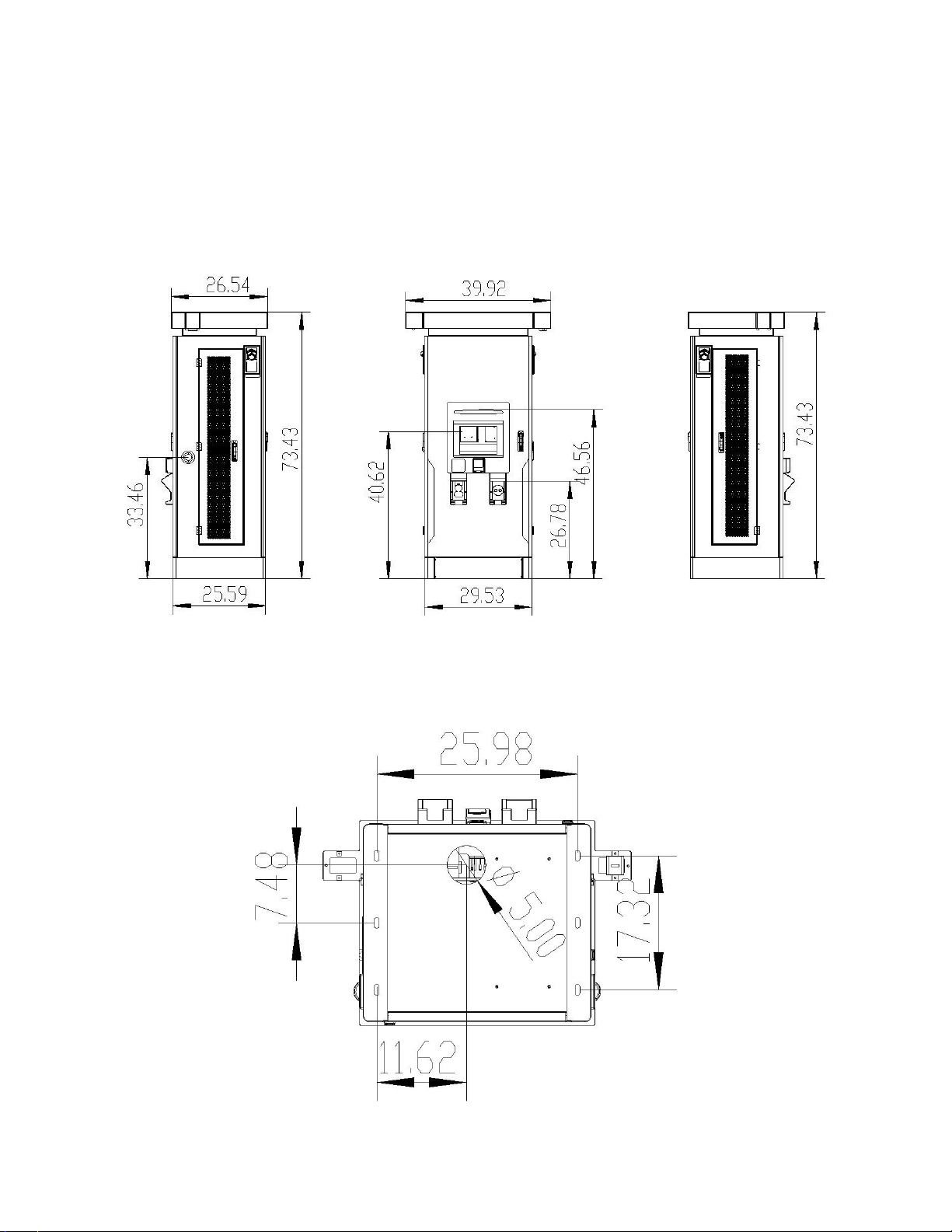
Charger Dimensions (LxDxH): 29.5”x 25.59”x 73.5”
Concrete Base
A flat concrete base with a vertical gradient of no more than 5% will be provided, with a provision for electrical
service wires to exit the concrete pad in the location as defined in this document.
The mounting pad shall be made of concrete cement, with approximate dimensions of 3 ft. wide by 2 ft. deep,
in order to accommodate the weight and dimensions of the base. Place the charger on the concrete mounting
pad with anchor studs using lock washers and nuts.
Mounting Pad
To meet ADA requirements, the concrete mounting pad shall not exceed 6 in. above the place of the parking
lot.
Barricade (Bollards)
Suitable bollards should be outfitted in order to restrict the approach of an electric vehicle (EV) to the charger.
Bollard position shall be in accordance with any applicable local code(s).
Input cables must be copper (3P+N); flexible copper is preferred. Please see the table, listed on the next
page, for cable gauge requirements.
Cables
Depending on the situation and cable type, the cables must be embedded in the ground with the proper cable
ducts.
Grounding
Reliable, protective grounding must be provided at all times. It is recommended to have a separate, dedicated
ground exclusively for the charger in order to ensure the highest degree of safety. The ground resistance
should be less than or equalto 4Ω. Copper cablein accordance withtheNECshallbe used to connect the charger
housingtotheexternal ground.
Breaker
A breaker (3P+N) with suitable current capacity, dependent upon the charger rating provided, is required. This
shall be in accordance with the NEC, typically 1.25 times the full load amperage.
Miscellaneous
Copper lugs (flat type) for the input cable and earth cable should be provided, and shall be sized dependent
on the size of the cable.
Do not let any flammable, explosive or flammable materials, chemicals, flammable vapors, and/or other
dangerous goods within close proximity of the charger.
Additional notes
The charger is rated IP54. In areas which see flooding, heavy rain, storms, snow, or other harsh weather
conditions, ChargeTronix recommends erecting a canopy over and above the charger for the equipment’s
protection.
Confirm beforehand that the intended installation site has a load capacity sufficient to support this equipment.
Charging cable length will vary between 13 ft. and 16 ft., depending on options.
8
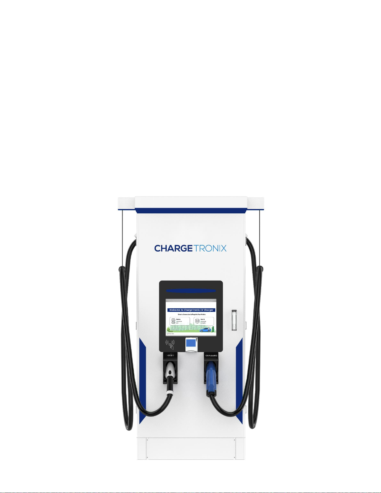
OUTLINE OF DRAWING - 160kW DCFC
Figure 1 Charger Outline
Figure 2 - Charger Bottom View

9
CHARGER ANATOMY
10
MECHANICAL INSTALLATION
CONCRETE PAD
A concrete pad constructed from 3,000-4,000 psi-concrete should be used. Electrical conduit for AC power
should be positioned such that it exits the concrete pad at the Main AC power line opening (see: Figure 2).
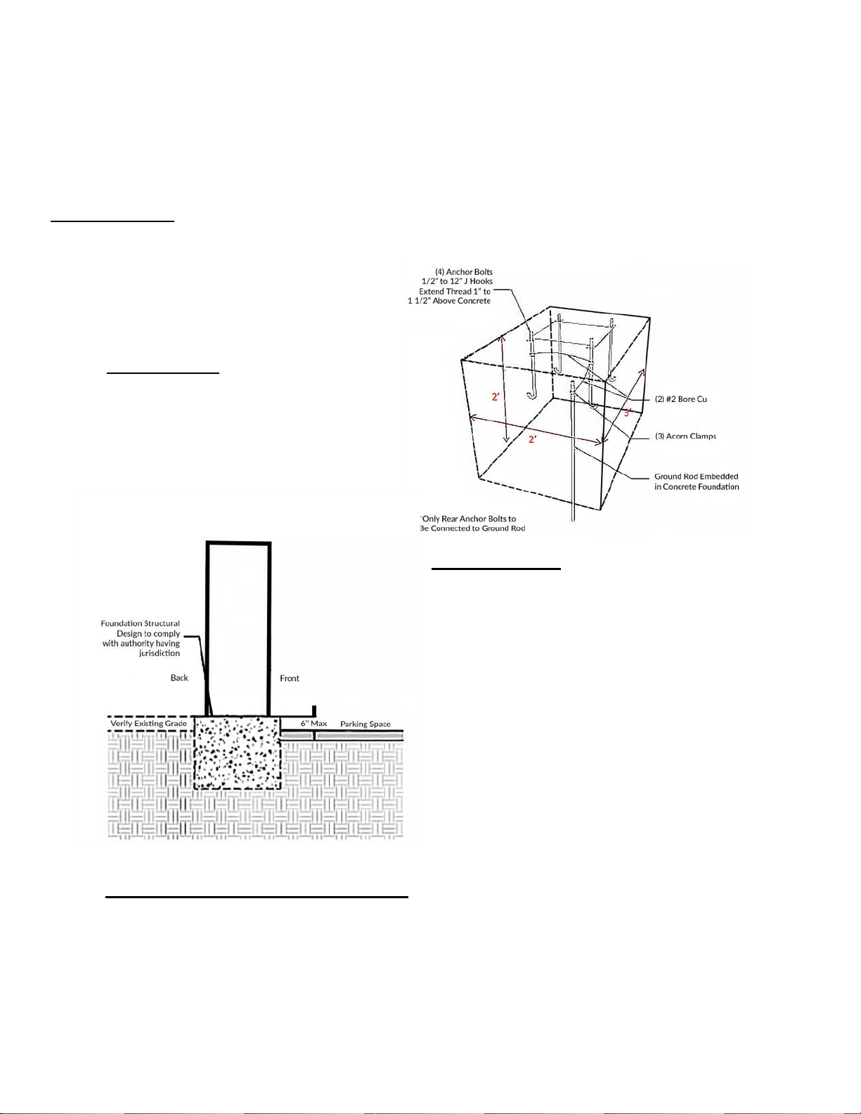
Alternative Anchor Installation –4 places
Use Hilti 1/2” KB-TZ SS 304 anchors (see: Appendix A Hilti Technical Information). Ensure that the
concrete has cured in accordance with the concrete and Hilti requirements. Position of the anchors shall
be in accordance to Figure 3 and installed per Hilti instructions. A ground rod will be needed and
installed.
PREPARATION
Ground Rod Connection: Use acorn
clamps to two #2 bare copper wire from
the ground rod to the first rear anchor bolt,
as shown on the diagram.
SIDE ELEVATION
▪
The concrete foundation needs to be sized
in accordance with local jurisdiction code(s). The
foundation referenced is 2 ft. deep and contains
rebar, as noted above.
▪
The foundation for the charger should have
a maximum height of 6 in. above finished grade.
‘Finished grade’ is defined as the location where the
user operating the charger will stand. Foundations
that extend higher than 6 in. above finished grade
will cause the charger controls to be above
ADA-compliant maximum standards and could result
in a failed inspection, possibly requiring the foundation
be lowered in order to meet ADA guidelines.

11
CHARGER INSTALLATION
ADA Consideration
There are a range of recommended best practices when installing electric vehicle chargers that incorporate ADA
requirements in the charger installation. Such practices include parking space striping, adequate allowance for wheelchair
movement, and bollards to protect the charger.
This equipment has been designed to meet ADA requirements when installed as prescribed in this manual; the prescribed
installation in this manual is also in accordance to the STANDARDS FOR ACCESSIBLE DESIGN for Americans with
Disabilities document.
2010 ADA Standards for Accessible Design: http://www.ada.gov/2010ADAstandards_index.htm
For information about the ADA, including the revised 2010 ADA regulations, please visit the Department’s website
www.ADA.gov ; or, for answers to specific questions, call the toll-free ADA Information Line at (1)800- 514-0301 (Voice) or
(1)800-514-0383 (TTY).
PLACING CHARGER ON MOUNTING PAD
1. A forklift will be required to move the charger into position. The charger with the crate will
weigh approximately 1050lbs. The charger without the crate weighs approximately 840 lbs.
To lift the charger, use either the forklift cut-out in the lower frame or the lifting eyes at the
top of the charger.
2. Remove the screws that hold the cover plates on the front and back of the base.
3. Before lifting the charger onto the mounting pad, remove the front/back cover plates which
will expose the slotted mounting hole. With the forklift, place the charger in position and
lower it onto the mounting pad while aligning the mounting pad studs with the slotted holes
in the charger base, ensuring that the electrical service also passes through the 4 in. cut-out
in the floor of the charger.
4. Install a large ½ flat washer, followed by a ½ split washer, and then fasten down the
appropriate nut and torque to Hilti specification. Remove the lifting eyes and plug the
threaded holes in the charger enclosure with appropriate fasteners, then seal with silicon.
5. Re-install the side cover plates.

12
INSTALL BASE FASTENERS - 4 PLACES
Install 1/2” x 1” x 1/8” thick washer, then the ½” lock washer and the 1/2-13 UNC nut and torque
to Hilti specification.

13
AC Input Power Wiring
INPUT VOLTAGE
AC Input Termination
COMPONENTS
•L1, L2, L3 are the 3 phase lines
•N is the Neutral
•PE is the protective earth or ground
Schematic diagram
of the input
connection of the
charger.
The charger requires an input
voltage of 480 VAC
(3 Phase + Neutral + Earth), 60Hz,
and a current of 215 amps.
Figure 3 –Main Breakers

14
HOW TO START A CHARGING SESSION
RFID CARD
1) Please select the connector compatible with your EV
2) Plug the connector into your EV
3) The display on the charger will provide options to select the authorization/payment method
4) Swiper the RFID card
5) The charging session will begin within 60 seconds
6) To stop charging: swipe the same RFID card again or use the STOP button the screen
QR CODE / MOBILE APP
1) Please select the connector compatible with your EV
2) Plug the connector into your EV
3) The display on the charger will provide options to select the authorization/payment method
4) Scan the QR code at the charger, or use the mobile app to begin the charging session
5) The charging session will begin within 60 seconds
6) To stop charging: Use the mobile app or use the STOP button on the screen
CREDIT CARD
1) Please select the connector compatible with your EV
2) Plug the connector into your EV
3) The charger display will provide options to select the authorization/payment method
4) Authorize your credit card. Make sure you have enough pre-loaded funds to charge
5) The charging session will begin within 60 seconds
6) The charging session will automatically stop after 100% charge is achieved. Or, you can use the
STOP button the charger screen.

15
CHARGER SETTINGS
Setting Parameters
During the initial installation, the setting parameters must be set by
the manufacturer, operating partner, or service partner. Changes
may only be made by trained personnel.
To access settings window:
1) Touch the ChargeTronix Logo
2) Provide the password. Password will be shared with the
authorized representative.
3) Select ‘system settings’
PARAMETER
VALUE
TIME ZONE
UTC+HH:MM
PSM QUANTITY
1
POWER OUT MODE
1
OCCUPLIED PLUG
1
PSM MAX VOLTAGE
1000
PSM MAX CURRENT
300
PSM MID VOLTAGE
200
PSM MID CURRENT
80
PSM MIN VOLTAGE
150
PSM MIN CURRENT
1
PMAX
20000
CCS NETWORK 1
ETH1
INSYS PLC MAC 1
00:00:00:00
TIME
2020-08-20
T20:46:25
.
S.NO
PARAMETERS
VALUE
REMARKS
1
NETWORK
ETH
Ethernet - DO NOT CHANGE
2
NETCFGFILE
/etc/network/interfaces
Path - DO NOT CHANGE
3
WLAN CONF
/home/guest/wpa_supplicant.conf
Path - DO NOT CHANGE
4
DEVICE IP
192.168.2.5
IP Address of Device
5
DEVICE GATEWAY
192.168.2.1
IP Address of Gateway
6
DEVICE NET MASK
255.255.255.0
IP Address of Mask
7
SERVICE URL
ws://localhost:8080/ocpp/
OCPP Server URL
8
DEVICE ID
1020180520001001
Device ID (alphanumeric)
9
CHARGE POINT VENDOR
ChargeTronix
Charger OEM - DO NOT CHANGE
10
CHARGE POINT MODEL
DC
Charger Type - DO NOT CHANGE
11
ADPATH
./pic
Path - DO NOT CHANGE
12
QRCODE NAME
NA
13
LANG
en
Path - DO NOT CHANGE
14
MODE
offline/record/upload/debug
Path - DO NOT CHANGE
15
CHARGING PIC
/img/charging_tata.jpg
Path - DO NOT CHANGE
16
IDLE PIC
/img/standby.jpg
Path - DO NOT CHANGE
17
LCM
1cm=/dev/tty54
Path - DO NOT CHANGE
18
LCM ENCODE TYPE
UNICODE
Encode - DO NOT CHANGE
19
LCM PASSWORD
123456
Password for Access
20
RFID
RFID0=/dev/ttyS1
Path - DO NOT CHANGE
21
PLUG1
GBTDC1:2=/dev/ttyS0
Path - DO NOT CHANGE
22
PLUG2
GBTDC2:2=/dev/ttyS0
Path - DO NOT CHANGE
23
DC1QRCODE NAME
NA
24
RFID ORIGINAL NUMBER
0
NA

16
MAINTENANCE AND SERVICE
DANGER: READ AND FOLLOW “SAFETY CONCERNS” AT THE BEGINNING OF THIS MANUAL BEFORE
OPERATING OR INSTALLING THIS DEVICE
EV Chargers require regular maintenance beyond installation to ensure the quality of the vehicle’s charges and
the continued value of your EV. Whether you’re installing a personal EV charger or one for public use, eventually
your device will require repair or maintenance services to keep the system working without issue.
MAINTENANCE PRECAUTIONS
Each of the capacitors in this device has high voltage for a time after shutting off the input power supply. Allow 1
minute after powering down, and then test with a voltmeter, before servicing internal components.
MAINTENANCE ITEMS
Perform periodic checks every 3 to 6 months based on the site conditions and the usage of the charger:
1) Check the input voltage and ensure it is within the acceptable limits
2) Check the ground/earth resistance and ensure it is within the acceptable limits
3) Clean the air filter periodically
4) Make sure that the power module lights are blinking green
5) Ensure that the charging cables are not worn out or showing wiring, and that the connector pins are clean
6) Make sure all of the air-cooling fans are working normally
VISUAL CHECK ITEMS
1) Check for abnormal sounds from running fans and power units
i If there is an abnormal sound present, please contact ChargeTronix at +(1)949-694-1644 for further
assistance
2) Check the device for abnormal odors, changes in inner materials, corrosion, anomalies in appearance, etc.
i If there are any anomalies, please contact a ChargeTronix support representative for further
assistance
3) Check for dust and dirt in this device regularly
i The air filters on the doors can be removed and cleaned using a vacuum cleaner or air blower
ii The cabinet can be cleaned using a vacuum cleaner
1 Please pay extra attention while using the vacuum cleaner, it should not apply pressure on the
control boards or any components
iii The dust on the components can be cleaned using a soft cloth
REPLACEMENT OF FIXED-LIFE COMPONENTS
To prevent the device from failure due to worn out components, it is necessary to replace the components before
they reach the end of their lifespan. Use the following replacement intervals as a guideline for the estimate of the
total running time.
oIntake and exhaust air filters (if present): Approximately three (3) years. The period depends upon the
site conditions.
oPlease keep in mind that the replacement interval of each part can vary depending on the usage
environment of the device.
Please contact a ChargeTronix support representative for further assistance when you replace the parts.

17
TROUBLESHOOTING
ERROR CODES
If an error occurs, check the nature of the error by referring to the following “Error Code List” and take appropriate
actions according to instructions by the manufacturer
ERROR
DESCRIPTION
POSSIBLE SOLUTION
ERROR FLAG 0
Lightning protection device failure
Check the SPD and GFCI circuit
ERROR FLAG 1
Insulation detection abnormal
The insulation check on the EV has failed.
Please try to charge different EV.
ERROR FLAG 2
Abnormal communication between
Insulation Monitor and Main Control Board
(CM)
Please check the connection between the IM
and CM boards. Check the LED lights on the
CM and IM
ERROR FLAG 3
Abnormal communication between TR
board and CM board
Please check the connection between the tr
and cm boards. Check the LED lights on the
CM and TR
ERROR FLAG 4
Electronic lock failure
Possible failure of the connector to lock on the
EV or the 24v supply voltage
ERROR FLAG 5
Internal use
Reserved
ERROR FLAG 6
Abnormal communication between DC
meter and main control board (CM)
Please check connection between the DC and
CM boards. Check the LED lights on the CM
and communication lines of the DC meter
FAULT TYPE SOLUTION
IP address communication failure or Server
Communication Failure
Please check the parameter settings interface IP address
information, such as the corresponding IP address is not correct,
please re-enter the address, restart the charger
AC input over voltage / under voltage
Please check the AC input side if the voltage is too high or too low,
excluding the input exception if there is a fault. Then, check the
parameters, the interface set, and the threshold set to ensure that
are correct
DC output over voltage / over current
Please check whether the output voltage and current are within the
range of parameter settings. If not, please check whether the output
voltage, current is too high, or whether the parameter setting is
reasonable
Card reader failure
The card reader is incorrectly wired, or the card reader is disabled.
Insulation fault
Please check whether the DC bus insulation is normal.
Monitoring board communication failure
Check whether the monitoring board communication line is correct
Charging connector connection failure
Charging connector is disconnected, please check whether the
charging connector is connected properly.
The emergency stop button is pressed
Check whether the emergency stop button is pressed, if it is, inspect
the charger and if everything is normal, release the emergency button
and restore the main breaker
Charging Session shutdown is not successful
MCU board and power module communication failure. Please press
emergency stop button to stop the charging. Check the MCU board
and power module CAN communication bus.
Physical Diagnostics at Charger/On Screen
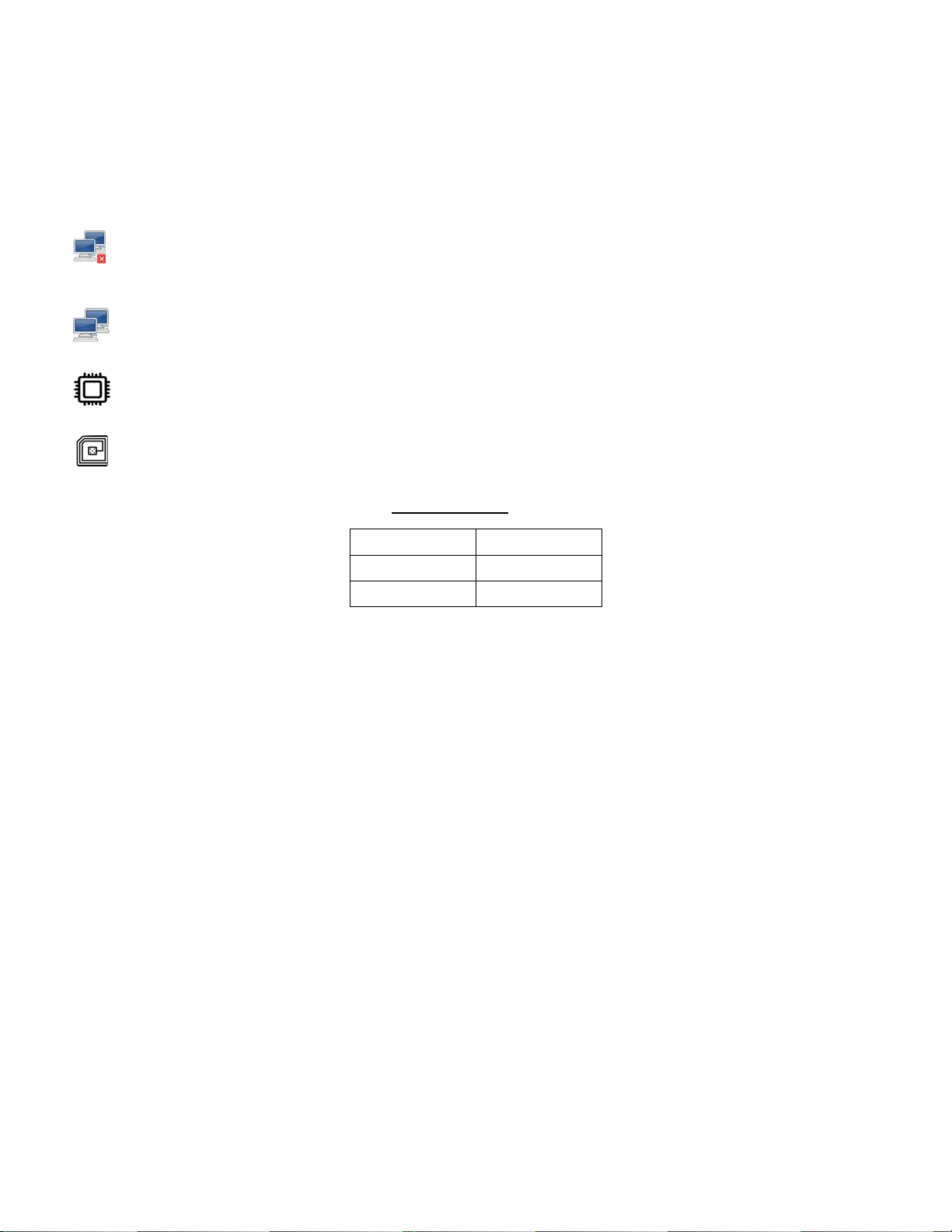
18
The icons below will be visible in the top-right corner of the charger screen:
This icon indicates that the charger is not connected to a server network. It can also indicate a loss of
internet connectivity. If no network is connected, the charger works as a stand-alone device with
ChargeTronix RFID cards.
This icon indicates that thechargerisconnectedtoa servernetwork; it canbe authorized with registered
RFID cards or the mobile app.
This icon indicatesthe working condition of the charger.If the icon flashes or is not visibleon the screen,
the controller is inactive.
This icon indicates that the RFID card reader is active. If the icon is not visible on the screen, the RFID
reader is inactive.
LED Indicator:
RED / Orange
Fault
Green
Charging
White
Available

19
CUSTOMER RESPONSIBILITIES
1) Operate the charger with the required protective devices, such as miniature circuit breakers
(MCBs), switches and properly installed cables
2) The operator/owner/customer is cautioned that any changes or modifications not approved by
ChargeTronix shall void ChargeTronix warranty policy
3) Write an emergency plan that instructs people what to do in case of emergency with the charger
4) Locate and prepare the site as per the instructions laid out in this document
5) Ensure that there is sufficient space around the charger to carry out any regular maintenance
work
6) Appoint a trained person(s) responsible for the safe maintenance/service of the charger
7) Neither ChargeTronix, nor any of its affiliates, shall be liable to the operator/owner/customer of
this product or third parties for damages, losses, costs, or expenses incurred as a result of an
accident, misuse, or abuse of this product or unauthorized modifications, repairs or alterations
to this product, or failure to strictly comply with ChargeTronix operating and maintenance
instructions
For any support on installation and commissioning, please contact below:
ChargeTronix
3120 Pullman St.
Costa Mesa, California, USA 92626
E: support@chargetronix.com
P: +(1)949-694-1644

20
WARRANTY
Warranty and Service Plan
ChargeTronix DC chargers come with the 2 years parts only standard warranty. However, we offer
service plans which cover parts and labor as well for an additional add-on fee. We can train your
operators or engineers and equip them with a basic understanding of troubleshooting and part
replacement to make sure the equipment downtime as well as the total cost of ownership is minimized.
Warranty Terms
LIMITED WARRANTY: Subject to the exclusions from warranty coverage set forth below, ChargeTronix
warrants that the Product will be free from any defects in materials and/or workmanship (the “Limited
Warranty”) for a period of two years after 30 days from the date of shipment or from date of the initial
installation whichever is earlier (the “Warranty Period”). If the Product becomes defective in breach of
the Limited Warranty, ChargeTronix will, upon written notice of the defect received during the Warranty
Period, either repair or replace, at ChargeTronix’s choice, the Product if it proves to be defective.
ChargeTronix will also pay for shipping charges for the failed part. If the returned part has not failed the
customer will pay for shipping charges for the replacement part and the associated returned part. Under
this guarantee, ChargeTronix liability is limited to repair or replacement of the product with the same or
equivalent, or reconditioned product warranted for the original warranty period. The warranty will not
include removal costs, reinstallation costs, loss of charger revenue, nor loss or damage of any kind
whatsoever, whether incidental, consequential or otherwise.
Exclusions From Limited Warranty
IMPORTANT: The Limited Warranty and on your Product shall not apply to defects, or service repairs,
resulting from any of the following:
•Damages due to normal wear and tear to charging cords, connectors, LCD/LED display, Touch Screen, or any product
alteration or modification, misuse, abuse, accident, vandalism, acts of nature, power surges, or use of software, parts, or
supplies not supplied by ChargeTronix, and causes other than manufacturing defects not covered by the warranty.
•Force Majeure –any occurrence or extraordinary event or circumstance beyond the control of ChargeTronix that is an act
of God or whether that occurrence is caused by war, riot, storm, (such as hurricanes, flooding, earthquake, volcanic
eruption, etc.), or other natural forces, including high input voltage from generators or lightning strikes or acts of nature or
other causes.
•Any Alteration or Modification of the Product in any way not approved in writing by ChargeTronix.
•Abuse, damage or otherwise being subjected to problems caused by negligence (including but not limited to physical
damage from being struck by a vehicle) or misapplication, or misuse of the Products by customers or end users.
•Any damage to the EV charger cord, unless such damage is caused by a manufacturing defect in the cord or connector
assembly.
•Improper site preparation or maintenance. That has been improperly installed, operated, handled, or used, including use
under conditions for which the product was not designed, use in an unsuitable environment, or use in a manner contrary
to the ChargeTronix Installation and Operations Manual or applicable laws or regulations.
•Damage because of accidents, extreme power surge, and extreme electromagnetic field.
•Use of the Product with software, interfacing, parts or supplies not supplied by ChargeTronix.
•ChargeTronix disclaims any liability for damage to product, property, or personal injury resulting in whole or in part, from
improper installation, maintenance or use that is not in accordance with ChargeTronix installation and maintenance
procedures.
•Maintenance or use that is not in accordance with ChargeTronix installation and maintenance procedures.
•That has been subjected to incidental or consequential damage caused by defects of other components of the electrical
system.
This manual suits for next models
5
Table of contents


