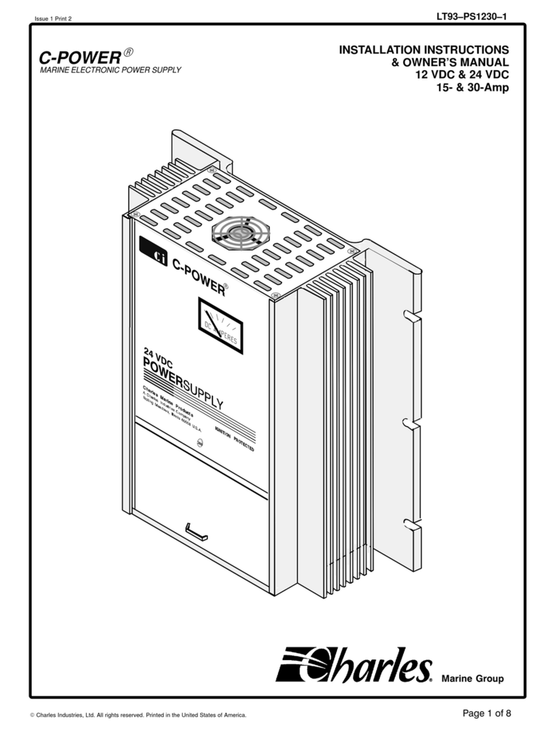
Charles C-Power Service manual

LT93−PS1230−1Issue 1 Print 3
1
Charles Industries, Ltd. All rights reserved. Printed in the United States of America.
C-POWERRINSTALLATION INSTRUCTIONS
& OWNER’S MANUAL
12 VDC & 24 VDC
15- & 30-Amp
MARINE ELECTRONIC POWER SUPPLY
Marine Group

LT93−PS1230−1 Issue 1 Print 3
2Charles Industries, Ltd. All rights reserved. Printed in the United States of America.
Contents
INTRODUCING... C-POWER 3. . . . . . . . . . . . . . . . . . . . . . . . . . . . . . . . . . . . . . . . . . . . . . . . . . . . . . . . . . . . . . . . . . . . . . .
Manual Purpose 3. . . . . . . . . . . . . . . . . . . . . . . . . . . . . . . . . . . . . . . . . . . . . . . . . . . . . . . . . . . . . . . . . . . . . . . . . . . . . .
IMPORTANT SAFETY INSTRUCTIONS 3. . . . . . . . . . . . . . . . . . . . . . . . . . . . . . . . . . . . . . . . . . . . . . . . . . . . . . . . . . . . .
Environmental Precaution 3. . . . . . . . . . . . . . . . . . . . . . . . . . . . . . . . . . . . . . . . . . . . . . . . . . . . . . . . . . . . . . . . . . . . .
C-Power Application Precaution 3. . . . . . . . . . . . . . . . . . . . . . . . . . . . . . . . . . . . . . . . . . . . . . . . . . . . . . . . . . . . . . .
Damaged C-Power Precaution 3. . . . . . . . . . . . . . . . . . . . . . . . . . . . . . . . . . . . . . . . . . . . . . . . . . . . . . . . . . . . . . . . .
Disassembly Precaution 3. . . . . . . . . . . . . . . . . . . . . . . . . . . . . . . . . . . . . . . . . . . . . . . . . . . . . . . . . . . . . . . . . . . . . .
Maintenance/Cleaning Precaution 3. . . . . . . . . . . . . . . . . . . . . . . . . . . . . . . . . . . . . . . . . . . . . . . . . . . . . . . . . . . . .
Grounding Precautions 3. . . . . . . . . . . . . . . . . . . . . . . . . . . . . . . . . . . . . . . . . . . . . . . . . . . . . . . . . . . . . . . . . . . . . . .
INSTALLING THE C-POWER 4. . . . . . . . . . . . . . . . . . . . . . . . . . . . . . . . . . . . . . . . . . . . . . . . . . . . . . . . . . . . . . . . . . . . . .
Choosing Mounting Hardware 4. . . . . . . . . . . . . . . . . . . . . . . . . . . . . . . . . . . . . . . . . . . . . . . . . . . . . . . . . . . . . . . . .
Mounting the C-Power 4. . . . . . . . . . . . . . . . . . . . . . . . . . . . . . . . . . . . . . . . . . . . . . . . . . . . . . . . . . . . . . . . . . . . . . . .
Mounting the Optional Splash Guard 4. . . . . . . . . . . . . . . . . . . . . . . . . . . . . . . . . . . . . . . . . . . . . . . . . . . . . . . . . .
Choosing Electrical Wiring Hardware 4. . . . . . . . . . . . . . . . . . . . . . . . . . . . . . . . . . . . . . . . . . . . . . . . . . . . . . . . . .
Choosing Wire Gauge 5. . . . . . . . . . . . . . . . . . . . . . . . . . . . . . . . . . . . . . . . . . . . . . . . . . . . . . . . . . . . . . . . . . . . . . . .
Making AC Connections on Terminal Block 1 (TB1) 6. . . . . . . . . . . . . . . . . . . . . . . . . . . . . . . . . . . . . . . . . . . . .
Making DC Connections on Terminal Block 2 (TB2) 6. . . . . . . . . . . . . . . . . . . . . . . . . . . . . . . . . . . . . . . . . . . . .
Closing the Access Door 6. . . . . . . . . . . . . . . . . . . . . . . . . . . . . . . . . . . . . . . . . . . . . . . . . . . . . . . . . . . . . . . . . . . . . .
Changing Internal Fuses 6. . . . . . . . . . . . . . . . . . . . . . . . . . . . . . . . . . . . . . . . . . . . . . . . . . . . . . . . . . . . . . . . . . . . . .
MAINTAINING THE C-POWER 7. . . . . . . . . . . . . . . . . . . . . . . . . . . . . . . . . . . . . . . . . . . . . . . . . . . . . . . . . . . . . . . . . . . . .
TROUBLESHOOTING THE C-POWER 7. . . . . . . . . . . . . . . . . . . . . . . . . . . . . . . . . . . . . . . . . . . . . . . . . . . . . . . . . . . . . .
WARRANTY & CUSTOMER SERVICE 7. . . . . . . . . . . . . . . . . . . . . . . . . . . . . . . . . . . . . . . . . . . . . . . . . . . . . . . . . . . . . .
Warranty 7. . . . . . . . . . . . . . . . . . . . . . . . . . . . . . . . . . . . . . . . . . . . . . . . . . . . . . . . . . . . . . . . . . . . . . . . . . . . . . . . . . . . .
Service Center and Repair Correspondence 7. . . . . . . . . . . . . . . . . . . . . . . . . . . . . . . . . . . . . . . . . . . . . . . . . . . .
SPECIFICATIONS 8. . . . . . . . . . . . . . . . . . . . . . . . . . . . . . . . . . . . . . . . . . . . . . . . . . . . . . . . . . . . . . . . . . . . . . . . . . . . . . . .

LT93−PS1230−1Issue 1 Print 3
3
Charles Industries, Ltd. All rights reserved. Printed in the United States of America.
INTRODUCING... C-POWER
Thank you for purchasing the C-POWERMarine Electronic Power Supply.
This manual covers the following models, listed by model number:
Table 1. 12 VDC & 24 VDC 15- & 30-Amp C-Power Model Numbers
Model Number Input Voltage Frequency Output Voltage
93−PS2415 120VAC* 60 Hz* 25.5 VDC
9C−PS2415 220VAC** 50/60 Hz** 25.5 VDC
93−PS2430 120VAC* 60 Hz* 25.5 VDC
9C−PS2430 220VAC** 50/60 Hz** 25.5 VDC
93−PS1230 120VAC* 60 Hz* 13.65 VDC
9C−PS1230 220VAC** 50/60 Hz** 13.65 VDC
* Will accept variances in input voltage from 90 to 135 VAC and variances in frequency from 45 to 65 Hz with no degradation of output.
** Will accept variances in input voltage from 180 to 270 VAC and variances in frequency from 45 to 65 Hz with no degradation of output.
Manual Purpose
With your personal safety in mind, this manual lists important safety precautions first, then covers installation,
operation, maintenance, troubleshooting and warranty and customer service information.
IMPORTANT SAFETY INSTRUCTIONS
SAVE THESE INSTRUCTIONS. This manual contains important safety and operating instructions
for the C-Power. Read the entire manual before usage.
Environmental Precaution
Do not expose the C-Power to rain, snow, or excessive moisture.
C-Power Application Precaution
These units are intended for hard-wired applications. Use of attachments not recommended or sold by Charles
Marine Products may result in risk of fire, electrical shock or personal injury.
Damaged C-Power Precaution
Do not operate the C-Power if it has received a sharp blow, been dropped, or otherwise damaged. See the sec-
tion in this manual on Warranty & Customer Service.
Disassembly Precaution
Do not disassemble the C-Power. See the sections in this manual on Maintaining the C-Power, Troubleshooting
the C-Power and Warranty & Customer Service.
Maintenance/Cleaning Precaution
To reduce risk of electrical shock, disconnect the C-Power from AC power and load before attempting any mainte-
nance or cleaning.
Grounding Precautions
When the C-Power is permanently mounted inside the boat, it must have a grounding conductor.
1. The C-Power should be connected to a metal, grounded, permanent wiring system. An equipment-
grounding conductor should be run with circuit wiring and connected through the C-Power housing
grommets to the equipment grounding (GRN) terminal on the C-Power.
2. Connections to the C-Power should comply with all local codes and ordinances.

LT93−PS1230−1 Issue 1 Print 3
4Charles Industries, Ltd. All rights reserved. Printed in the United States of America.
INSTALLING THE C-POWER
Choosing Mounting Hardware
As with any marine equipment, secure mounting is of utmost importance. The bolts or screws used to secure the
C-Power must be 1/4-inch in diameter, backed with a flat washer, and kept vibration-free with a split-ring lock
washer. If using bolts, they must be long enough to be secured on both sides of the bulkhead. If using screws,
they should be at least 1 inch long. All hardware should be corrosion-resistant.
Mounting the C-Power
All corrosion-resistant mounting hardware should be readily available. Follow the steps below to mount the C-
Power to the bulkhead.
Step Action
1. Hold the C-Power vertically flush on the bulkhead.
2. Mark the mounting holes.
3. Remove the C-Power.
4. Drill the mounting holes.
5. Insert one side of the mounting hardware half-way into the drilled mounting holes.
6. Align the mounting slots on the C-Power with the secured hardware and slide the C-Power’s mounting
flange under the washers.
7. Insert the mounting hardware for the other side.
8. Secure all mounting hardware.
Mounting the Optional Splash Guard
If ordered, position and install the optional splash guard (Figure 1) over the C-Power so that the back flange bot-
tom rests on top of the C-Power. This insures proper vertical spacing for ventilation. For optimum splash protec-
tion, be sure to center the splash guard horizontally over the C-Power. Secure with 1/4 inch diameter screws,
approximately 1/2 inch long.
Do not operate this unit without the green wire connected to the C-Power and to suitable ground at
shore connection.
DANGER
Note: Read this manual and all precautions before installing or making connections!
Choosing Electrical Wiring Hardware
The C-Power is intended for hard-wiring in a permanent application. Conduit or other appropriate marine electrical
installation hardware should be used.

LT93−PS1230−1Issue 1 Print 3
5
Charles Industries, Ltd. All rights reserved. Printed in the United States of America.
To AC
ground bus
(green)
WHT BLKGRN TB1 TB2
40A/32V FASTACTING
SLO−BLO
F2
Note 1
ToAC hot (black)
ToAC neutral bus (white)
Notes
1. AC stranded wire.
2. DC stranded wire.
3. Optional Splash Guard, part # 21-104589.
4. Internal fuse size is for 30-amp model. See Table 4 for 15- and 30-amp model fuse size.
PCB
DC
Fuse
(see Table
4 & Note 4)
AC
Fuse
(see Table
4 & Note 4)
AC power source
circuit breaker
(min. size15 amps)
F1
(PS2430 shown)
15A/250V
Access to PCB:
and
TB1 & TB2
F1, F2 & F3 Fuses
+DC −DC
LOAD
+−
Note 2
Note 3
F3
Figure 1. C-Power 15- & 30-Amp Block Diagram
Choosing Wire Gauge
Use Table 2 and Table 3 to determine the appropriate wire gauges. Avoid unnecessarily long runs of either AC or
DC power lines.
Before working on electrical equipment, first determine there is no live power! Double check power
connections.
DANGER
Table 2. Minimum Wire Size to Input of C-Power
120 VAC SHORE POWER INPUT TO C-POWER
Model Number AC Amp Max 25’ Length 50’ Length 100’ Length
PS2415 10 16 AWG 14 AWG 10 AWG
PS2430 12 14 AWG 12 AWG 10 AWG
PS1230 10 16 AWG 14 AWG 10 AWG
220 VAC SHORE POWER INPUT TO C-POWER
PS2415 5 18 AWG 16 AWG 14 AWG
PS2430 6 16 AWG 14 AWG 12 AWG
PS1230 5 18 AWG 16 AWG 14 AWG

LT93−PS1230−1 Issue 1 Print 3
6Charles Industries, Ltd. All rights reserved. Printed in the United States of America.
Table 3. Minimum Wire Size from Output of C-Power
Model Number DC Amp Max 15’ Length 25’ Length
PS2415
15
12 AWG
12 AWG
PS2415
15
12 AWG
12 AWG
PS2430
30
10 AWG
10 AWG
PS2430
30
10 AWG
10 AWG
PS1230 30 10 AWG 10 AWG
External connections to the C-Power shall comply with the U.S. Coast Guard Electrical Regulations
(33CFR183 subpart I).
WARNING
Making AC Connections on Terminal Block 1 (TB1)
After determining the wire lengths and gauges, make the AC wiring connections to TB1. (Refer to the Block Dia-
gram in Figure 1.) To make connections to the terminal blocks:
Step Action
1. Remove the small screw in the center of the unit that secures the sliding door to the top cover
2. Gently slide the door up until it stops
3. Bring the AC input wire in through the left side access hole on the bottom of the C-Power
4. Connect the WHT terminal to the white (neutral) input
5. Connect the BLK terminal to the black (hot) AC input
6. Connect the GRN terminal to the green (ground) input.
Making DC Connections on Terminal Block 2 (TB2)
After the appropriate wire lengths and gauges have been determined, make the DC connections to TB2. (Route
the DC wire through the right-side access hole on the bottom of the C-Power.) TB2 has one positive (+) terminal
and one negative (−) terminal.
Closing the Access Door
Before closing the access door, make sure that all electrical connections have been made properly. Also check
that all wiring is properly dressed with no exposed, bare wires. Pull down the C-Power access door and secure it
to the top cover with the small screw provided.
Changing Internal Fuses
Irregular conditions may cause one or more of the internal fuses to blow. ALWAYS determine there is no live pow-
er before replacing a fuse. To access the fuses, remove the small screw in the center of the unit that secures the
sliding door to the top cover. Slide the access door up until it stops. The AC fuse (F1) is located just above the
AC terminal block (TB1). The DC fuses (F2 & F3) are located above the DC terminal block (TB2). When replacing
fuses, use only fuses of the exact type and rating (See Table 4). Before reapplying power, pull down the access
door to close it. Once down, secure the access door to the top cover with the small screw provided.
Table 4. Internal Fuse Replacement Sizes
Model Number AC Input (F1) DC Output (F2) DC Output (F3)
PS2415 12-Amp/250 Volt SLO-BLO 30-Amp/32 Volt FAST ACTING
PS1230 12-Amp/250 Volt SLO-BLO 30-Amp/32 Volt FAST ACTING 30-Amp/32 Volt FAST ACTING
PS2430 15-Amp/250 Volt SLO-BLO 40-Amp/32 Volt FAST ACTING 40-Amp/32 Volt FAST ACTING

LT93−PS1230−1Issue 1 Print 3
7
Charles Industries, Ltd. All rights reserved. Printed in the United States of America.
MAINTAINING THE C-POWER
There are no adjustment or maintenance requirements for the C-Power other than cleaning the outside cabinet
with a dry cloth. Periodically have all connections checked by a qualified service person, especially if the boat is
operated in heavy, pounding seas.
TROUBLESHOOTING THE C-POWER
If there is a problem with the C-Power, first check all connections and retest. If all connections are good, see if
the problem is covered in Table 5. If the problem is not covered in Table 5, or if the C-Power still malfunctions af-
ter performing the solution given, contact Charles Marine Products for technical assistance.
Table 5. Troubleshooting Suggestions
# Problem Solution
1. The ammeter deflects
in a counterclockwise
direction.
Disconnect the unit immediately. Examine wiring instructions again to assure proper
connections. A movement in a counterclockwise direction or a full-scale movement
indicates excessive current. A wiring error is suspected. A voltmeter can monitor the
voltage when the C-Power is turned on.
2. Internal red LED on. The unit is at half-power because the ambient air is too hot. The unit may be at
half-power because the fan is not working. Full power will be restored when the
temperature returns to normal.
WARRANTY & CUSTOMER SERVICE
Warranty
The CHARLES Marine & Industrial Group warrants the unit will be free from defects in materials and workman-
ship that cause mechanical failure for one (1) year, as set forth in the Limited Warranty. Notice of any alleged de-
fect in material or workmanship must be provided within thirty (30) days of discovering the problem, and within the
warranty period. Follow the procedure outlined below to obtain warranty service.
Service Center and Repair Correspondence
Note: Do not attempt to service the unit. Contact the Service Center.
To contact the Service Center via telephone directly:
800−830−6523 (Toll Free)
217−932−2317 (Voice)
217−932−2473 (FAX)
Call to obtain a Returned Materials Authorization (RMA) number prior to returning any unit to Charles Industries.
Return the unit for repairs to the Service & Repair Center address below:
Charles Industries, Ltd.
Marine & Industrial Group
503 NE 15th Street
Casey, IL 62420-2054
USA
Correspondence can be sent to Corporate Headquarters via the address below:
Note: Do not return the unit to this address.
Charles Industries, Ltd.
Marine & Industrial Group

LT93−PS1230−1 Issue 1 Print 3
8Charles Industries, Ltd. All rights reserved. Printed in the United States of America.
5600 Apollo Drive
Rolling Meadows, IL 60008-4049
USA
847−806−6300
www.charlesindustries.com
SPECIFICATIONS
The specifications for the C-Power are listed in Table 6 and Table 7.
Table 6. C-Power PS2415 & PS1230 Model Specifications
Feature U.S. Metric
Weight 9 pounds 4.1 kilograms
Height 13.25 inches 33.7 centimeters
Width 9.5 inches 24.1 centimeters
Depth 3.7 inches 9.4 centimeters
AC Input* 120 VAC nom
220 VAC nom
*See the label on the side of the charger for the operating voltage.
Table 7. C-Power PS2430 Model Specifications
Feature U.S. Metric
Weight 10 pounds 4.5 kilograms
Height 15.25 inches 38.7 centimeters
Width 9.5 inches 24.1 centimeters
Depth 3.7 inches 9.4 centimeters
AC Input* 120 VAC nom
220 VAC nom
*See the label on the side of the charger for the operating voltage.
This manual suits for next models
6
Table of contents
Other Charles Power Supply manuals
Popular Power Supply manuals by other brands
Allen-Bradley
Allen-Bradley 1734-EP24DC installation instructions
PASCO
PASCO SF-9288 instruction sheet

Telemark
Telemark ST Series instruction manual
Rockwell Automation
Rockwell Automation 1606-XLE80E manual
Delta Electronics
Delta Electronics Delphi E48SR12007 datasheet

Dr.X Works
Dr.X Works BH1-L product manual
