Charnwood PT10S User manual

1
PLANER THICKNESSER
OWNERS MANUAL
MODEL: PT10S & PT12S
Please Note:
This machine requires
a 16amp electric supply
with a Type C breaker
Charnwood Machinery, Cedar Court, Walker Road, Hilltop Industrial Estate,
Bardon Hill, Leicestershire, LE67 1TU
Tel. 01530 516 926 Fax. 01530 516 929
email: sales@charnwood.net website: www.charnwood.net

2
GENERAL SAFETY RULES
WARNING: Do not attempt to operate the machine until you have read thoroughly and understood
completely all instructions, rules, etc. contained in this manual. Failure to comply may result in
accidents involving fire, electric shock, or serious personal injury. Keep this owner's manual and
review frequently for continuous safe operation.
1. Know your machine. For your own safety, read the owner's manual carefully. Learn its application
and limitations, as well as specific potential hazards pertinent to this machine.
2. Make sure all tools are properly earthed.
3. Keep guards in place and in working order. If a guard must be removed for maintenance or
cleaning, make sure it is properly replaced before using the machine again.
4. Remove adjusting keys and spanners. Form a habit of checking to see that all keys and adjusting
spanners are removed from the machine before switched it on.
5. Keep your work area clean. Cluttered areas and workbenches increase the chance of an accident.'
6. Do not use in dangerous environments. Do not use power tools in damp or wet locations, or expose
them to rain. Keep work areas well illuminated.
7. Keep children away. All visitors should be kept a safe distance from the work area.
8. Make workshop childproof. Use padlocks, master switches and remove starter keys.
9. Do not force the machine. It will do the job better and be safer at the rate for which it is
designed.
10. Use the right tools. Do not force the machine or attachments to do a job for which they are not
designed. Contact the manufacturer or distributor if there is any question about the machine's suitability
for a particular task.
11. Wear proper apparel. Avoid loose clothing, gloves, ties, bracelets, and jewellery which could get caught in
moving parts. Non-slip footwear is recommended. Wear protective hair covering to contain long hair.
12. Always use safety glasses. Normal spectacles only have impact resistant lenses. They are not safety
glasses.
13. Do not over-reach. Keep proper footing and balance at all times.
14. Maintain the machine in good condition. Keep the machine clean for best and safest performance. Follow
instructions for lubrication and changing accessories.
15. Disconnect the machine from power source before servicing and when changing the blade.
16. Never leave the machine running unattended. Turn the power off. Do not leave the machine until it comes
to a complete stop.
17. Do not use any power tools while under the effects of drugs, alcohol or medication.
18. Always wear a face or dust mask if operation creates a lot of dust and/or chips. Always operate the tool in a
well ventilated area and provide for proper dust removal. Use a suitable dust extractor.
ADDITIONAL RULES FOR PLANER/THICKNESSERS
1. This machine is designed for use with wood. Attempting to plane or thickness any other materials will result
in damage to the machine, potential fire risk and/or health hazards.

3
2. The machine is designed for indoor use only.
3. Connection to a suitable dust extraction system is highly recommended. If you must use the machine on its
own, you will need to stop it, unplug it from the mains and thoroughly clean it at regular intervals. Continuing
to use the machine when it is clogged with shavings will result in damage to it, potential fire risk and/or health
hazards.
4. The machine should only be used on the stand provided.
5. Always hold the work firmly on to the table, using push pads when necessary.
6. Never use the planer/thicknesser with the guard and/or dust hood removed.
7. If planing or thicknessing a long piece of timber, provide additional support at the same height as the table.
8. Switch the machine off and unplug it before removing any debris.
9. Be aware of the possibility of kickback.
10. Do not modify this machine in any way or use it or anything other than its designated purpose. Neither the
manufacturer nor the suppliers will be liable for any damage or injury caused by incorrect assembly, operation
or electrical connection of this machine.
Risk of Injury! Wear Eye Wear Ear
Never reach into Protection Protection
a running cutter block
Rating Description
Trade: Suitable for daily use by professional woodworkers.
Continuously rated, high power and a heavy duty construction. Typically used by several different
operators in a small or medium sized business. Will be used up to the machines maximum limit
with some long work periods. Expected maximum use of 1000 hours annually.
Please Note: Using a product in excess of its rating will void the manufacturer’s free warranty.
Specification
PT10S PT12S
Motor (induction) 2200w (3hp)/240v/50hz 3000w (4hp)/240v/50hz
Recommended Breaker size 16 Amps (Type C) 16 Amps (Type C)
Planer width 250mm (10”) 310mm (12”)
Maximum Depth of Cut Planer 3.0mm 3.0mm
Fence tilt 0 to 45° 0 to 45°
Max. Depth of Cut Thicknesser 2.5mm 4.0mm
Thicknessing capacity 5mm to 180mm 5mm to 230mm
Number of cutters 44 (4 x 11) TC 56 (4 x 14) TC
Cutter Size 15mm x 15mm x 2.5mm, R=150
Weight 175kg 208kg
Rating Trade Trade
Product Guarantee 1 Year 1 Year

4
Unpacking
Open The Crate
This product is packed into 1 wooden
crate.
To open the wooden crate:
Cut the vertical straps
Use a pry bar to release the nails around
the base
Lift off the complete lid.
Remove Loose Items
Remove the plastic cover,
The fence,
Carton of assembly parts.

5
Remove the side panel
Use a cross head screwdriver to loosen 6
screws.
3 on each side of the panel.
Lift and then remove the side cover.
Unbolt From The Base
The machine is fixed to the pallet base
with 3 bolts.
Use a 13mm spanner to undo the 3
securing nuts.
This part of the assembly requires 2
people:
Lift the machine off the pallet base.
Do not dispose of any of the packaging until the machine has been completely assembled and tested.
In the unlikely event that the product needs to be returned, the original packaging will be required.

6
Identify The Loose Parts
Side Fence Service Tools
5 Spare Cutters & Bolts Spring Plate
Fence Bracket
Cutter Guard
4 Fixing Bolts Support Arm
Push Pad
4 Feet
Assembly
Remove the protective paper from the planing tables and clean the rust preventer from the table using
WD40 or similar, and a soft cloth.
Fit The Feet
Lift one side of the machine and support
with a block of wood to gain access the
hole for each foot.
Remove the top nut from the foot, pass
the stud through the hole and then refit the
top nut.
Lock in place with a pair of 16mm
spanners.
Refit the side Cover.
Fit The Fence Support Bracket
Attach the bracket to the machine using 4
bolts.
Secure with a 6mm Allen key

7
Fit the Fence
Slide the dovetailed end of the fence into
the support bracket.
Push it all the way to the limit stop.
Use the ratchet handle to lock the fence.
Fit The Cutter Guard Support Arm
Hold the arm up against the side of the
machine.
Pass a 5mm Allen key through the access
hole to tighten the bolt.
Repeat for the other bolt.
Fit The Cutter Guard
Use a cross head screw driver to remove
the retaining screw from the end of the
guard.
Insert the Spring Plate into the Support
Arm, then slide the Cutter Guard into the
end of the arm, underneath the Spring
Plate.
Refit the retaining screw.
Lock the guard using the locking knob
Hang the Push Pad
Use the hanging point provided to keep
the push pad within reach at all times.

8
Clean The Thicknessing Table
To access the thicknessing table:
Unlock the planing beds, one lock at each
end
Raise the beds into the vertical position
Swing the extractor hood over cutter block
Remove the protective paper and clean
the rust preventer from the table using
WD40 or similar, and a soft cloth.

9
Using the Planer Thicknesser
Feed Direction
PLANING MODE
Side Fence
Cutter Guard Height Adjuster
Outfeed Table
Cutter Guard Lock
Table Lift Lock
On / Off Switch
Infeed Table
Infeed Table Lock
Planing Depth Scale
Planing Depth Adjuster
Push Pad
THICKNESSING MODE
Lifting Handle
Dust Hose Connection
Planing Beds Release Catch
Extractor Hood
Drive Rollers Lever
Emergency Stop Button
Planing Bed Lock
Thicknessing Scale
Thicknessing Bed Height Lock
Digital Position Indicator
Feed Direction Thicknessing Bed Height Adjuster

10
PLANING MODE
With the machine set up in planing mode:
Use the Cutter Guard Height Adjuster to adjust the height of the Cutter Guard, so that the work
piece can fit underneath.
Set the Planing Depth Adjuster to the desired setting, reading off the Planing Depth Scale. If in
doubt, set the depth to 0.5mm
Connect a dust extractor to the 100mm diameter outlet.
Start the machine, wait for it to get up to full speed.
Lay the work piece flat on the Infeed Table and push it over the cutter block. Use a push stick or
push pad to ensure hands are kept well away from the cutters.
Pick up the work piece and return it to the starting position. Make as many passes as necessary to
achieve a flat planed finish.
When planing taller pieces, over 60mm, undo the Cutter Guard Lock and slide the Cutter Guard
away from the Side Fence just enough to provide clearance for the workpiece.
SWITCHING MODES
To move from planing mode to thicknessing mode:
Engage the drive rollers by moving the Drive Rollers Lever into the upper position.
Release the tables using the 2 Planing Bed Locks, one at each end: Rotate the handle towards
the centre of the machine, pull out away from the cutter block and then lower the handle.
Use the Lifting Handle to move the tables into a vertical position. This process is spring assisted,
but take care as the tables are heavy. The tables are automatically locked in the vertical position.
Swing the Extractor Hood up and over the cutter block, until it clicks into place.
THICKNESSING MODE
With the machine set up in Thicknessing mode:
Measure the thickness of the work piece.
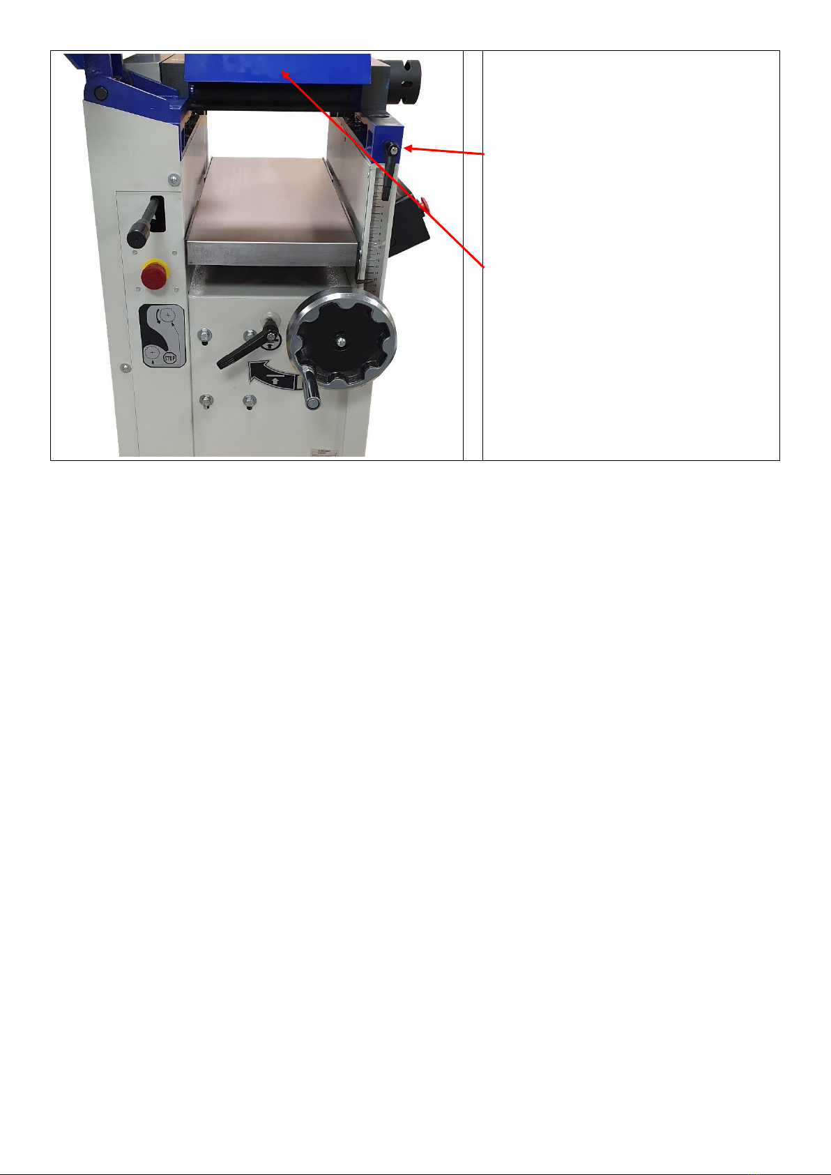
Rotate the Thicknessing Bed Height Adjuster anti-clockwise to unlock the thicknessing bed.
Wind the Thicknessing Bed Height Adjuster handwheel clockwise to raise the thicknessing bed.
1 rotation is equal to 2mm adjustment.
Read off the scale or use the Digital Position Indicator, with accuracy down to 0.1mm, to set the
bed at the starting thickness. Then raise the bed another 1 –2.5mm, depending on how much
stock is to be removed.
Tighten the Thicknessing Bed Height Lock.
The feed direction is the opposite direction to planing mode.
Start the machine, wait for it to get up to full speed.
Lay the work piece flat on the end of the table. Slide it forward until you feel the drive rollers take it
from you. Let go of the work piece and walk to the other end of the machine to support the work
piece as it is fed out of the thicknesser.
A safety bar will prevent you from trying to make too big a cut. If the timber hits the safety bar,
lower the table to take a smaller cut.
Make as many passes as necessary to get the desired finished dimension.
If making multiple components, consistency is best achieved by feeding them all through at one
depth, before adjusting the table height and feeding them all through again.

11
3
2 4
1
SWITCHING MODES
To move from thicknessing mode to planing mode:
Disengage the drive rollers by moving the Drive Rollers Lever into the lower position.
Lower the thicknessing bed all the way down.
Release the extractor hood from the retaining pin and swing the Dust Hood underneath the cutter
block.
Support the tables with one hand and pull back the Planing Beds Release Catch.
Then lower the tables to the horizontal position. The weight is supported by springs, but take care
as they are heavy.
Lock the tables in place with the 2 Planing Bed Locks.
General Guide
When faced with a rough sawn piece of timber which requires planning on all 4 sides and taking
down to a specific finished dimension, follow this guide:
•Set the machine up for planing.
•Identify the flattest of the two wider faces on the timber. (Face 1 on diagram)
•Pass that side over the planer as many times as
necessary until a flat and smooth finish is achieved.
•Hold the planed side firmly against the side fence and pass the narrow side (Face 2 on
diagram) over the planer as many times as necessary until a flat and smooth finish is
achieved.
•You should now have two planed sides at 90 degrees to each other.
•Set the machine up for thicknessing.
•Pass the timber through the thicknesser with the wider already planed side (Face 1 on
diagram) facing down against the bed. Continue until the desired thickness for the timber is
reached.
•Finally, pass the timber through the thicknesser with the planed narrow side (Face 2 on
diagram) facing down against the bed. Continue until the desired thickness for the timber is
reached.

12
Cutter Replacement
Disconnect the machine from the supply
The cutter block is fitted with 4 rows of
Tungsten carbide cutters, 11 in each row.
Each cutter has 4 sides and 4 cutting
edges.
A cutter can be rotated by 90 degrees to a
new position to renew the cutting edge.
Each corner is numbered so you can keep
track of which edge has already been
used.
If one edge becomes damaged by a chip of
nick, it can be rotated or replaced
individually.
Eventually the cutters will become blunt
and then the entire row should be rotated
or replaced at the same time.
To change a cutter:
Rotate the cutterblock so the cutter to be
changed is at the top of the arc.
Use a T20 Torx key to undo the locking
screw.
Turn anticlockwise to undo.
Refit the cutter with a new edge
uppermost.
The back edge of the cutter should fit
tightly against the back stop on the cutter
block.
Fit the locking screw and tighten it firmly.

13
Troubleshooting
Problem
Cause
Remedy
Machine does not start
Emergency stop activated
Twist to release the red
emergency stop button
Faulty switch
Replace switch
Cutter Guard not fitted
Check the alignment of the
micro switch
Only starts when Green
button is held down
Faulty switch
Replace switch
MCB trips on Start up
MCB rating is too low
Replace with Type C 16amp
Short circuit in cable or plug
Repair the damage
Machine hums but does not
start
Start capacitor failed
Replace start capacitor
Cutter block runs at half
speed, with lack of power
Run capacitor failed
Replace run capacitor
Motor running but cutter
block is not rotating
Broken or stretched drive
belt
Replace drive belt
Motor slows down during the
cut
Depth of cut is too great
Take a smaller cut
Dust & Chip collector hood
is blocked
Clear the blockage and
ensure the extractor is
functioning correctly
Cutters are blunt
Rotate or replace the cutters
Feed rollers slipping
Build up of dust and sap on
the table
Clean the table
Long lines or ridges along
the length of planed timber
Nicked or chipped cutters
Rotate or replace the cutters
Excessive snipe
Outfeed table is set too low
Align the outfeed table to the
height of the cutter when at
the top of its arc
Operator pushing down on
the trailing end of the timber
Eliminate downward
pressure on trailing end
Timber not supported as it
leaves the planer
Support the timber as it
leaves the outfeed end of the
planer

14
Declaration of Conformity for CE Marking
Charnwood Declare that Woodworking Planer & Thicknesser, Models PT10s and PT12S
Conforms with the following EU Directives: Machinery Directive 2006/42/EC
Electromagnetic Compatibility 2014/30/EU
Conforms with the following UK Regulations: Supply of Machinery (Safety) Regulations 2008
Electromagnetic Compatibility Regulations 2016
And further conforms to the machinery example for which the EC type examination Certificate No. BM
50458388 & AE 50458339 have been issued by TUV Rheinland LGA Products GmbH, Tillystrasse 2,
90431, Nurnberg, Germany.
I hereby declare that equipment named above has been tested and found to comply with the relevant
sections of the above referenced specifications. The machinery complies with all essential requirements of
the directives and regulations.
Signed: Dated: 04/01/2023 Location: Leicestershire
Richard Cook, Director
Please dispose of packaging for the product in a responsible manner. It is suitable for recycling. Help to
protect the environment, take the packaging to the local amenity tip and place into the appropriate
recycling bin.
Only for EU countries
Do not dispose of electric tools together with household waste material!
In observance of European Directive 2002/96/EC on waste electrical and electronic equipment (EEE)
and its implementation in accordance with national law, electric tools that have reached the end of their
life must be collected separately and returned to an
environmentally compatible recycling facility.
Your local refuse amenity will have a separate collection area for EEE goods

15
Charnwood PT10S & PT12S Parts Diagrams
Drawing A:

16
Drawing B:

17
Drawing C:

18
Charnwood PT10S & PT12S Parts List
Part No.
Description
Part No.
Description
001
Base Stand
002
Cover Plate
003
Flat Washer M5
004
Screw M5 x 8
005
Foot
006
Nut M10
007
Right Inner Plate
008
Countersunk Screw M5 x 6
009
Screw M5 x 50
010
Nut M5
011
Motor
012
Bolt M8 x 20
013
Nut M8
014
Spring Washer
015
Washer M8
016
Driving Pulley
017
Screw M6 x 8
018
V Belt
019
Protective Cover
020
Screw M5 x 25
021
Flat Washer M4
022
Nut M5
027
Screw M10 x 35
028
Flat Washer
040
Push Pad
050
Trim Cover
051
Trim Plate
052
Screw M5 x 10
053
Screw M4 x 6
054
Screw M4 x 16
055
Wire Clip
056
Nut M4
057
Screw M4 x 12
058
Wire Clip
059
Nut M4
103
Screw M8 x 30
104
Spring Washer
105
Screw M6 x 35
106
Nut M6
107
Support Plate
108
Lifting Tube Bracket
109
Locking Plate
110
Guide
112
Screw M8 x 16
113
Hex Socket Screw M6 x 10
114
Seal Ring
115
Screw M8 x 16
116
Lifting Sleeve
117
Thicknesser Table
118
Limiting Plate
119
Countersunk Head Screw M4 x 6
120
Pointer
121
Screw M4 x 6
122
Screw M4 x 6
123
Scale
124
Bolt M6 x 20
125
Flat Washer
126
Locking Block
127
Nut M6
128
Washer
129
Oriented Bar
131
Locking Plate
132
Washer
133
Bolt M6 x 20
134
Handwheel
135
Handwheel Bar
136
Nut M12
137
Retaining Ring
138
Support Bush
139
Locking Rod
140
Locking Handle
141
Bolt M6 x 65
142
Spring Washer
143
Flat Washer
144
Retaining Ring
145
Gear Shaft
146
Flat Key A5 x 12
147
Retaining Ring
148
Flat Washer
149
Helical Gear
150
Thrust Ball Bearing
151
Bush

19
152
Lead Screw
153
Elastic Pin
154
Nut M10
155
Flat Washer
156
Gear Box
157
Elastic pin
158
Nut M8
159
Nut M6
171
Block
172
Hex Socket Head Screw M6 x 25
173
Digital Readout
174
Hex End Set Screw M5 x 8
201
Right Support Bracket
202
Flat Washer
203
Spring Washer
204
Screw M8 x 25
205
Retaining Ring
206
Eccentric Rod
207
Adjustable Handle
208
Left Support Bracket
209
Supporting Axle
210
Screw M6 x 35
211
Shaft
212
Anti Kickback Finger
213
Limit Axis
214
Elastic Cylindrical Pin 6 x 20
215
Hex Socket Set Screw M6 x 10
216
Hex Socket Set Screw M8 x 12
217
Right Table Bracket
218
Torsion Spring
219
Right Axle
220
Infeed Table
221
Bolt
222
Washer
223
Nut M10
224
Screw M8 x 25
225
Rear Support Base
226
Nut M10
227
Limit Screw
228
Small Support Base
229
Support Pole
230
Pin
231
Split Ring
232
Flat Washer
233
Spring Washer
234
Screw M6 x 18
235
Support Pole
236
Elastic Pin 5 x 16
237
Small Support Base
238
Nut M10
239
Nut M10
240
Flat Washer
241
Eccentric Shaft
242
Hex Socket Screw M6 x 12
243
Limit Block
244
Bolt M5 x 35
246
Nut M5
247
Flat Washer 12
248
Retaining Ring 12
249
Right Support Plate
250
Hex Socket Screw M10 x 1 x 30
251
Mut M10 x 1
252
Countersunk Head Screw M6 x 14
253
Nut M10
254
Hex Flange Bolt M10 x 45
255
Nut M10
256
Locking Support Base
257
Nut M10
258
Handle Lever
259
Handle
260
Screw M4 x 6
261
Pointer
262
Driving Connecting Rod
263
Connecting Rod
264
Cylindrical Pin
265
Driven Connecting Rod
266
Screw M6 x 14
267
Retaining Ring 8
268
Shield
269
Right Shield
270
Depth Gauge
271
Washer 8
272
Handle
273
Countersunk Head Screw M6 x 10
274
Square Handle
275
Screw M8 x 25
276
Front Cover
277
Screw M8 x 30

20
278
Spring Washer
279
Flat Washer
280
Left Support Plate
281
Left Support Base
282
Outfeed Table
283
Left Axle
284
Left Table Bracket
285
Eccentric Sleeve
286
Screw M8 x 30
287
Cylindrical Pin 6 x 20
288
Protective Cover
289
Screw M6 x 10
290
Flat Washer 6
292
Hex Socket Screw M8 x 12
293
Hex Socket Screw M8 x 20
294
Screw M8 x 30
295
Spring Washer
296
Flat Washer
297
Screw M6 x 16
298
Cylindrical Pin
310
Hex Socket Screw M6 x 16
311
Sleeve
312
End Sleeve
313
Roller
314
Drive Roller
315
Flat Key A5 x 16
317
Hex Socket Screw M6 x 8
318
Sprocket
319
Screw M5 x 8
320
Chain
321
Chain
322
Stud Bolt
323
Flat Washer
324
Nut M8
325
Spring
326
Nut M10
327
Connecting Plate
328
Handle
329
Spring
330
Flat Washer 10
331
Pin
332
Long Pin
333
Washer 6
334
Bolt M6 x 10
336
Tension Spring
337
Tensioner
338
Ball Bearing 6303
339
Pin
340
Flat Washer 10
341
Nut M10
343
Screw M6 x 10
344
Ball Bearing
345
Retaining Ring
346
Sprocket
347
Sprocket II
349
Ball Bearing 6901
350
Sprocket III
352
Friction Wheel
353
Screw M6 x 16
355
Sprocket
356
Retaining Ring 24
357
Retaining Ring 12
358
Screw M5 x 16
359
Nut M5
401
Retaining Ring 25
402
Screw M6 x 10
403
Bearing Base
406
Protective Plate
407
Spring Washer 6
408
Screw M6 x 14
409
Flat Key A6 x 20
410
Screw M6 x 8
411
Driven Wheel
413
Cutter Block
415
Compressed Spring
416
Blade
417
Wedge
418
Square Head Bolt
430
Spiral Cutter Block
430.1
Cutter 15 x 15 x 2.5mm, R=150
430.2
Countersunk T20 Torx Screw
497
Anti Kickback Finger
498
Nut M6
499
Elastic Cylindrical Pin 5 x 16
501
Extractor Hood
502
Rubber Pad
503
Locking Plate
504
Bolt M6 x 10
This manual suits for next models
2
Table of contents
Other Charnwood Planer manuals