Chase Research CC4 User manual

CRC Ltd, Cool Works, Unit 2 Neepsend Ind. Est., Parkwood Rd, Sheffield S3 8AG, UK.
Tel: +44 114 278 0711
Director: Dr. S.T. Chase Secretary: Dr. L.C. Kenny
Registered in England & Wales, No. 4643351 VAT registration No. GB 763 8558 84
CONTINUOUS 4He SORPTION COOLER
TYPE CC4
GENERIC INSTALLATION AND OPERATING INSTRUCTIONS
Photo shows a typical CRC CC4 sorption cooler

2
Contents
1. GENERAL HANDLING.....................................................................................................................3
2. SAFETY OF CHASE RESEARCH CRYOGENICS PRODUCTS...............................................................3
2.1. Pressure Equipment Directive 97/23/EC (Pressure Equipment Regulations 1999)..............3
2.2. Pressure Systems Safety Regulations 2000...........................................................................3
2.3. Safe Operation.......................................................................................................................4
2.4. Risk Assessment ....................................................................................................................4
3. A BRIEF DESCRIPTION OF THE SORPTION COOLER UNIT..............................................................6
4. INSTALLATION...............................................................................................................................7
4.1. Mechanical ............................................................................................................................7
4.3. Electrical ................................................................................................................................8
5. ATTACHING YOUR EXPERIMENT TO THE SORPTION COOLER......................................................9
5.1. Radiation shielding................................................................................................................9
6. OPERATION: quick-start guide....................................................................................................10
6.1. Cooldown and commence continuous operation...............................................................10
7. OPTIMISING THE PERFORMANCE OF YOUR SORPTION COOLER ...............................................11
7.1. Varying the cycle time.........................................................................................................11
7.2. Varying the cycle steps........................................................................................................12
7.3. PID stabilisation of the CC4 .................................................................................................13
9. STANDARD Pin-Out Assignments ...............................................................................................14
10. cc4 OPERATIONAL SEQUENCE FOR INITIAL COOLDOWN AND EXTENDED OPERATION ........15
THIS GENERIC OPERATING MANUAL describes how to install and operate a CRC CC4 sorption cooler.
It is accompanied by an Excel file that contains the validation test data and the calibration files that
are specific to the sorption cooler unit that you have purchased.
You are advised to make a note of the location of the Excel file specific to your sorption cooler unit.
CRC can provide another copy on request if you send us the Serial Number engraved around the rim
of your cooler’s main plate.
This manual was last updated in January 2022.

3
1. GENERAL HANDLING
WARNING!
CRC SORPTION COOLERS CONTAIN HELIUM GAS AT HIGH PRESSURE.
Do not crush, twist or bend the unit. Avoid applying mechanical stresses. Do not
heat the unit above room temperature. Keep in a sealed cryostat, or in the
shipping box and brace in which it came.
Do not hold or lift the unit by means of the cold heads.
Do not tamper with the copper capillary fill tubes.
Avoid the use of acid fluxes when soldering in the vicinity of the cooler. Chloride
based fluxes will corrode stainless steel and could damage your cooler.
Always allow the unit to warm to room temperature before allowing air into your
cryostat. Opening the air valve of a cold cryostat is likely to damage the unit.
After unpacking the sorption cooler according to the instructions supplied, the sorption cooler
should be immediately transferred into the host cryostat. The shipping brace doubles as a stand for
the sorption cooler, though when used as a stand, the screws through the top aluminium plate into
the cold heads should NOT be in place. When picking the sorption cooler up, it should be firmly
grasped by the main plate.
2. SAFETY OF CHASE RESEARCH CRYOGENICS PRODUCTS
2.1. Pressure Equipment Directive 97/23/EC (Pressure Equipment Regulations 1999)
This CRC sorption cooler unit is manufactured in accordance with Sound Engineering Practice. The
volume and gas pressure within the sorption cooler are such that the equipment falls below the
lower classification limit in Annex II of the Pressure Equipment Directive. Hence the requirements
for Conformity Assessment do not apply and no Declaration of Conformity can be made, or CE
marking applied.
The sorption cooler is covered by Article 3 Paragraph 3 of the Pressure Equipment Directive, which
states: “Pressure equipment and/or assemblies below or equal to the limits in sections 1.1, 1.2 and
1.3 and section 2 respectively must be designed and manufactured in accordance with the sound
engineering practice of a Member State in order to ensure safe use. Pressure equipment and/or
assemblies must be accompanied by adequate instructions for use and must bear markings to
permit identification of the manufacturer or of his authorized representative established within the
Community. Such equipment and/or assemblies must not bear the CE marking referred to in Article
15.”
2.2. Pressure Systems Safety Regulations 2000
This sorption cooler unit does not contain a pressure x volume product exceeding 250 bar-litres
hence PSSR regulations 5(4), 8-10 and 14 do not apply. This means that the system does not require
a written scheme of examination. The sorption cooler is not ‘mobile’ in the sense intended in the
PSSR hence the owner has duties under these regulations to ensure that a) the safe operating limits
are not exceeded; b) the unit is operated in accordance with these instructions; c) the unit is

4
returned to Chase Research Cryogenics Ltd in the event that any maintenance is required. The
sorption cooler contains no user-serviceable parts.
2.3. Safe Operation
The safe operating temperature range of this sorption cooler is 0 to 320 K.
2.4. Risk Assessment
CRC sorption coolers contain Helium gas under pressure. The stored energy of the system is less
than 50 bar litres. All system components are integrity tested during manufacture; the slightest leak
will make the sorption cooler lose its stored gas and cease to function. A unit that has leaked
presents no risks whatever to the user; the following risk assessment applies therefore only to
functional units.
Hazards and consequences
Accidental damage to the sorption cooler unit could result in the sudden release of pressurised
gases, causing mechanical failure of the unit and potential injury (or damage to surrounding
instruments) from ejected debris.
Possible events leading to failure are: overheating of the unit, for example in a fire; dropping or
crushing of the unit; twisting or bending of the gas tubes. Mechanical damage to the unit is most
likely to occur during assembly of the instrument of which the sorption cooler forms part.
Risks without controls in place
It is extremely unlikely that the above events will lead to danger. Chase Research Cryogenics Ltd has
produced more than two hundred sorption cooler units of various designs, which are in use for a
range of applications worldwide. To date there has never been a sudden failure of a sorption cooler
unit –indicating that with normal use (including inevitable handling mishaps) the units have an
excellent safety record. User experience to date shows that accidental mechanical damage to
sorption cooler units is likely to result in slow leaks, not sudden failures.
Controls in place
The controls that are in place to eliminate (as far as reasonably practicable) the risks arising from
mechanical damage to a sorption cooler unit are:
•This written instruction manual, containing warnings about the potential risks arising from
damage to the unit and alerting the user to more risky operations;
•Instructions that the unit should not be used if it has been subjected to overheating,
dropping, crushing, bending or twisting;
•A warning label on the transit box that the instructions should be read prior to handling the
unit.
The applications for which sorption cooler units are intended make it impossible to place warning
labels on the unit itself. However if the sorption cooler is incorporated into another instrument, that
instrument should carry a warning label to alert the user that the sorption cooler contains no user-
serviceable parts and should not be disassembled.
Risks with controls in place
Providing users read and follow this instruction manual the risks are negligible.

5
2.5. Safe Transportation
The unit must be correctly re-installed in its shipping brace before transportation either by road or
air. Follow the unpacking instructions provided in reverse order and contact CRC for advice if
needed. The cooler+brace should be securely packed into the cooler’s rigid shipping box, which
contains polystyrene or similar cushioning material to firmly hold the unit and prevent any
movement within the box. Add extra pieces of packing foam to ensure that the heavy pumps cannot
move in transit. Place the rigid shipping box into a much larger outer carton surrounded by at least
5-10 cm soft fill on all sides, this should ensure that if dropped the impact shock will be absorbed by
the overpack, and not transmitted to the cooler itself.
For transportation purposes CRC sorption coolers are classified under UN 2857, Class 6A (6=Other
articles containing gas under pressure; A=asphyxiant gas). Special Provision 119 applies:
Refrigerating machines include machines or other appliances which have been designed for the
specific purpose of keeping food or other items at a low temperature in an internal compartment,
and air conditioning units. Refrigerating machines and refrigerating machine components are not
subject to the provisions of ADR if they contain less than 12 kg of gas in Class 2, group A or O
according to 2.2.2.1.3, or if they contain less than 12 litres ammonia solution (UN No. 2672).
This special provision means that the cooler does not need to be either labelled or shipped as
hazardous or dangerous goods, whether transported by road or by air, provided that it is
appropriately packed.
Ensure that the outer carton is clearly labelled as fragile with ‘This Way Up’ labels and add Shock
Indicators if you are handing the consignment to third-party couriers, as these should deter rough
handling.

6
3. A BRIEF DESCRIPTION OF THE SORPTION COOLER UNIT
The CC4 sorption cooler is shown in the figure below. Continuous cooling of the 1K cold head is
achieved by alternately cycling the two 4He module at intervals, such that the 1K cold head is always
being cooled by one of the modules. In use, the sorption cooler is inverted, i.e. the cold head will be
at the bottom. The main plate needs to be thermally sunk to the cold head of a cryocooler at 4K or
below, see section 4.1 for more information. The 1K-head is used to extract heat from the
experiment, see section 5 for more information. The pumps and heat switches can reach up to 50K
during operation, these need to be radiation shielded from the head, for more information see
section 5.1. All electrical connections are mounted on the main plate on a stack of MDM connectors,
see section 4.2 for more information.
The following short names for the various parts of the sorption cooler are used throughout this user
manual:
Short name used in this manual
Refers to the sorption cooler part
1K-head
The cold head of the split condenser module
4-head
4He module head
4-Pump
4He module pump
4-Switch
Heat Switch for the 4He pump
The two 4He modules (which are identical) will be referred to as Module A and Module B.
He4 module
He4 Pump
1K cold head
Electrical
connector
Split
condenser
module
Not visible: heat switches
and heat straps
Main plate
Head Support
structure

7
4. INSTALLATION
4.1. Mechanical
Before installing the unit in your cryostat, be sure to carefully remove any pieces
of foam packing from around the pumps, as mentioned in the unpacking
instructions.
There should be no need to touch the heat switches or heat straps during
installation or normal operation of the sorption cooler. The heat switches can be
easily damaged, and if bent or twisted are likely to fail.
This sorption cooler is designed to be pre-cooled using a mechanical cryocooler such as a GM or
pulse tube operating at 4K or below. The thermal link to the cryocooler should be made from gold
plated copper to ensure excellent thermal contact between the sorption cooler and the cryocooler.
Mounting holes are provided on the main plate for attaching the sorption cooler to your cryostat
cold plate. To attach the sorption cooler to the 4K stage of the cryocooler there are twelve M4
clearance holes distributed around the periphery of the circular main plate (note: UNC6 clearance
holes can be substituted at customer request). A CAD file of your sorption cooler can be provided
on request to aid with interfacing.
Because the cooling down of the heads depends upon gas convection, and on
liquid helium collecting in the heads fed by gravity, the sorption cooler mustbe
kept close to vertical with the heads downwards.
Ensure spring washers are
under every bolt head, these
will take out differential
thermal contraction that
might otherwise cause
loosening of the bolts, and
thus compromise thermal
contact.

8
4.3. Electrical
All electrical connections are brought out to stack of three MDM-SSP connectors (2 x 15 pin, 1 x 9
pin) mounted onto the main plate. Pin-outs are listed at the end of this instruction manual. The
table below summarises the temperature sensors installed on the CC4.
ITEM
Calibration
Options
1K-head RuO2
Generic Lakeshore Cryotronics or
Scientific Instruments Inc.
Individually calibrated
sensors available on request
4-head RuO2
Generic housekeeping sensors,
calibration supplied by CRC
Lakeshore sensors available
on request
Switch diode
Generic –supplied by CRC Ltd
Pump diode
Generic –supplied by CRC Ltd
Voltage / current requirements for driving the heater and thermometers are summarised in the
table below:
ITEM
NUMBER
IMPEDANCE/
JUNCTION VOLTAGE
VOLTAGE/
CURRENT
4-pump heater
1
300approx.
20 to 25 V
Heat switch heater
1
10k
5 V
Diode thermometers
3 or 4
0.5 to 1.8V
10µA DC
4-head RuO2thermometer
1
1kto 3k
1µA max.
Generic (i.e. standard calibration) RuO2sensors from Lakeshore Cryotronics or Scientific Instruments
Inc. are the default option on the head of all CRC sorption coolers. Individually calibrated ‘CERNOX’
or RuO2 sensors are only fitted (at additional cost) at the customer’s request. The thermometer on
the 1K-head is operated as a 4-wire device and should ideally be driven by an AC current no greater
than 1µA. Calibration tables for all thermometer sensors are in the Excel data file that accompanies
each unit. Generic diode calibration curves for the pump diode and heat switch diode are supplied
as standard. The diode thermometers require excitation with currents of 10A DC.
The heat switch heater typically requires about 5V to keep the switch in the ‘ON’ state with the
absorber pod at greater than ~20K, and it will cool to the off state (T < 10 K) in ten to fifteen minutes.
The pump heater impedance is typically 300. To operate the sorption cooler it is necessary to
periodically warm the 4-pumps to between 40 and 45k. A heater current of up to 100 to 130mA will
heat the 4-pump rapidly; lower heater currents will result in slower heating. Try to ensure that the
lead-in wiring to the pump heater is not unduly dissipative and is appropriately heat-sunk.

9
5. ATTACHING YOUR EXPERIMENT TO THE SORPTION COOLER.
This model of sorption cooler provides just one point at which heat may be extracted from a user’s
experiment mounted on a separate cold table, which is the 1K-head. There are several M3 holes
tapped in this surface for thermal connections between your experiment and the sorption cooler
(note UNC4 holes can be substituted at customer request).
While fixing experimental equipment to the cold head, extreme care should be
taken not to torque or bend the gas pipes. Always support the cold head against
the applied torque.
Under no load, and with the main plate at ~4K, the cold head will run at an average temperature of
about 900mK. The temperature fluctuates periodically due to the antiphase cycling of the 4-
modules; the average temperature and the amplitude of the fluctuations will depend on the
software used to control the CC4 and there are different optimisation strategies that are possible,
depending on whether low temperature or temperature stability is more important. This is
discussed further in Section 7. When the 1K-head is loaded the temperature increases, typical data
are given in Figure 1 below. Load data for your specific sorption cooler are supplied in the Excel data
file that accompanies your unit.
5.1. Radiation shielding
The 1K-head, and any cold table/experimental equipment/detector assembly you attach, must be
properly radiation shielded at around 4K to achieve satisfactory operation. The cold table should be
thermally connected to the 1K-head with a copper heat strap. No other mechanical attachments to
the sorption cooler unit are necessary for satisfactory operation. If your sorption cooler
performance is not meeting the specification, this is likely to be due to a radiation load. Check your
radiation shielding and consider adding extra multi-layered insulation around your radiation shields,
or around the pump side (“warm side”) of the CC4.
10
6. OPERATION: QUICK-START GUIDE
6.1. Cooldown and commence continuous operation
The basic cooldown steps for the CC4 are as follows:
•Turn on the GM cryocooler and wait unit both heat switches have turned off.
•Turn on the pump heaters to keep both pumps warm (around 45K) until both 4-heads
and the 1K-head are cold (4K or below)
•Turn the heat off pump A, turn on heat switch A to cool 4-head A to
~1K. The 1K-head will also cool to ~1K at this point.
•15 minutes later: Turn the heat off pump B, turn on heat switch B to cool 4-head B to
below 1K.
•With all heads now below 1K the periodic re-cycling can begin.
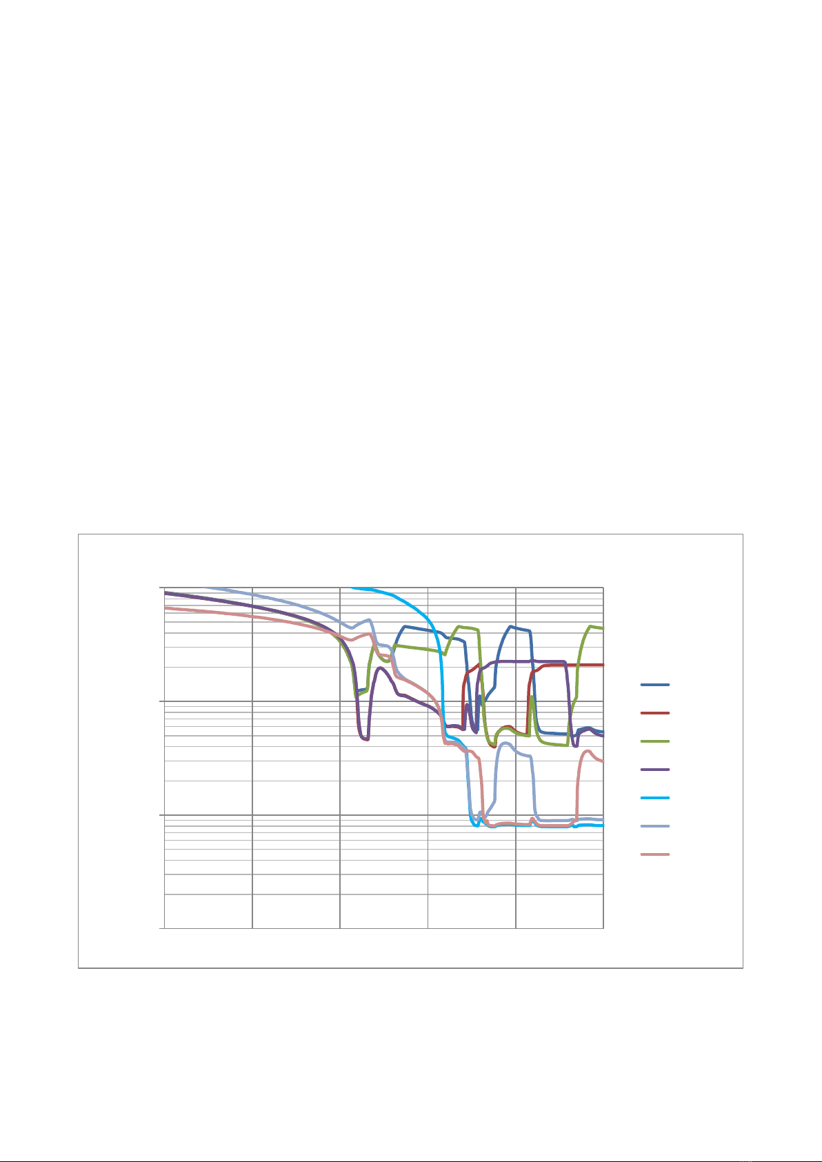
This cooldown sequence is illustrated in Figure 2 below, which shows a typical cooldown from room
temperature to 1K (at ~1350 minutes). The key steps to observe are:
-Heat switches turn off just after t=1200
-Pump heaters are turned on shortly after this
-All heads are at ~4K around t=1340
-Switch A turned on just before t=1350 for final cooldown of 4-head A and 1K-head
-Switch B turned on 15 minutes after for final cooldown of 4-head B
-Ready to begin cycling at t=1350
Figure 2
0.1
1
10
100
1000 1100 1200 1300 1400 1500
Temperature K
Time Mins
CC4 initial cooldown and establish cycling
Pump A
Switch A
Pump B
Switch B
1K-head
4head A
4head B

11
6.2 Established alternate cycling for continuous operation.
The cycle time that is optimum for your CC4 will depend on your cryocooler’s power and the heat
load that your experiment imposes, but is likely to be in the range 30-100 minutes. The examples in
this manual use 100 minutes cycle time.
The cycling steps are explained more fully in Section 8 and can be summarised as follows:
•Switch A off
•Heat pump A (the 1K-head is being cooled by 4-head B)
•Keep pump A warm while 4-head A cools
•Switch A on
•Switch B off
•Heat pump B (the 1K-head is being cooled by 4-head A)
•Keep pump B warm while 4-head B cools
•Switch B on
This sequence can be repeated for as long as required.
7. OPTIMISING THE PERFORMANCE OF YOUR SORPTION COOLER
Running the CC4 with programmable power supplies under software control enables a range of
options to tailor the CC4 performance to the user’s own set-up and application. Options include:
•Varying the cycle time;
•Varying the timing of individual cycle steps;
•Varying the rates at which pumps and/or heat switches are heated.
You are recommended to experiment with your own system to optimise its performance in your
setup, for your application.
7.1. Varying the cycle time
The cycle time cannot be reduced below the time taken to heat and cool the pumps and the heat
switches. Very rapid heating cycles are only possible if the CC4 is run using a powerful GM/PT
cryocooler that is able to rapidly remove the heat dumped by the pump when the heat switch is
turned on. This heat pulse temporarily increases the temperature of the main plate, and if it gets
too warm (above ~10K) there is a danger that the other heat switch (the ‘off’ switch) will also turn
on. Disrupting the cycle. In general, for better temperature stability and low running temperature,
we advise gentle turn-on of pump and heat switch heaters (see below).
The cycle time cannot be lengthened beyond the expiry time of either He4 module in the CC4, i.e.
the time taken to evaporate all of the Helium 4 liquid in the 4-head. When a module expires it will
start to warm up, and will warm the 1K-head before the other module takes over the cooling. The
expiry time will depend on the load imposed on the head, both by parasitic loads internal to the
CC4, and by external loads due to the user’s experiment. Your CC4’s technical datafile will specify
a recommended cycle time for your specific unit, when working under a specified applied external
load. If you find that your experiment causes the modules to expire, you should seek to reduce the
load (i.e. improve radiation shielding and heat sinking), and then try reducing the cycle time.

12
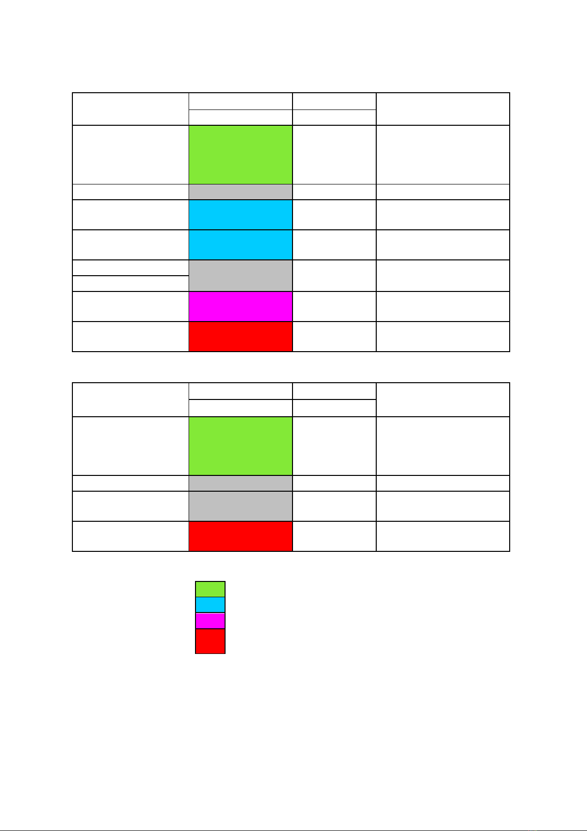
7.2. Varying the cycle steps
Figure 3 shows an example of a cycling sequence (100 minute cycle time) optimised to give a low
base temperature for the CC4. In this example the pump heaters are turned on gently at first, and
they are turned off as soon as the 4-heads stop cooling rapidly. This minimises the heat loading on
the CC4.
Figure 3
In the second example shown in Figure 4 the cycling sequence is optimised to reduce temperature
fluctuations at the 1K-head.
Figure 4

13
The cycling time in Figure 4 is again 100 minutes, but here, the heat switches are turned on gently
at first, and the pumps are kept warm for a longer portion of each cycle. This means that the heat
loading on the CC4 is greater overall, however the rate of heat transfer to the main plate when the
cycle is switched is reduced, meaning that the temperature fluctuations transmitted to the 1K-
head are also reduced.
7.3. PID stabilisation of the CC4
Finally, the CC4 wiring is configured to enable PID stabilisation of the temperature through
the application of a varying external load via a feedback loop to compensate the inbuilt
fluctuations. Many different PID optimisation schemes are possible and the user is
encouraged to experiment to find the one that best suits their own set-up.
PID optimisation does require the application of loads to the 1K-head and so the CC4 will
run at a higher, though more stable, temperature when it is used.
14
9. STANDARD PIN-OUT ASSIGNMENTS
He4 modules
Function
female 15 pin
Drive current
TYPE
PIN #
or voltage
RTD THERMOMETER V+
1
100nA AC
RTD THERMOMETER V-
generic 6951
9
Or low voltage
RTD THERMOMETER I+
2
Driver
RTD THERMOMETER I-
10
e.g. V<0.5mV
not used
3
PUMP DIODE I+
DC2018
4
10A
PUMP DIODE I-
11
SWITCH DIODE I+
DC2018
5
10A
SWITCH DIODE I-
12
not used
6
not used
13
SWITCH HEATER I+
10kOhm
7
2.5 to 3 Volts
SWITCH HEATER I-
14
PUMP HEATER I+
300 Ohm
8
50 to 100 mA
PUMP HEATER I-
15
13 to 15 V
Function
female 9 pin
Drive current
TYPE
PIN #
or voltage
RTD THERMOMETER V+
Lakeshore
1
100nA AC
RTD THERMOMETER V-
or Scientific
6
Or low voltage
RTD THERMOMETER I+
Instruments
2
Driver
RTD THERMOMETER I-
7
e.g. V<0.5mV
nc
3
nc
4
nc
8
PID heater
100 kOhm
5
50 to 100 mA
9
0 to 5 V
Resistance thermometer
Diode thermometer
Low power heater (a few mW)
High power heater (up to about
2W)

15
10. CC4 OPERATIONAL SEQUENCE FOR INITIAL COOLDOWN AND EXTENDED OPERATION
Step
Pump
A
Pump
B
A
B
Working status
Notes
heater
heater
Heat
switch
Heat
switch
1
OFF
OFF
OFF
OFF
Wait for both heat
switches to turn off
Pre-cooling with GM/PT
2
ON
ON
OFF
OFF
Wait until both 4-
head temperatures
are less than 4K
Heat both pumps to ~45 K, turn
power down (or off) to keep them at
40-45K
3
OFF
OFF
ON
OFF
Turn on heat switch
A, 4-head A and 1K-
head cool down
heads should cool to ~1K fairly
rapidly
4
OFF
OFF
ON
ON
Turn on heat switch
B, 4-head B cools
down
All heads should now be at ~1K
Begin alternate cycling for extended operation. Repeat steps 5 to 11 at your chosen cycle interval
5
OFF
OFF
OFF
ON
Turn off heat switch
A,4-head A
temperature rises to
~4K
The 1K-head is being cooled by
Module B
6
ON
OFF
OFF
ON
Turn on Pump A and
Heat to 45K,4
head A desorption
A more gradual heat will reduce
temperature fluctuations but raise
the average temperature
7
OFF
OFF
OFF
ON
Turn off Pump A
heater,Wait for
thermal relaxation
time
The time taken for this step will
depend on the cryocooler power.
Typically ~10 minutes
8
OFF
OFF
ON
ON
Turn on heat switch
A,4 head A starts
to cool down
A gradual heat switch turn on will
reduce temperature fluctuations
9
OFF
OFF
ON
OFF
Turn off heat switch
B,4head B
temperature rises
to~ 4K
The 1K-head is being cooled by
Module A
10
OFF
ON
ON
OFF
Turn on Pump B and
Heat to 45K,4head
B desorption
See step 6
11
OFF
OFF
ON
OFF
Turn off Pump B
heater,Wait for
thermal relaxation
time
See step 7
Table of contents
Popular Accessories manuals by other brands


ORION TELESCOPES & BINOCULARS
ORION TELESCOPES & BINOCULARS 51874 instruction manual

TFK
TFK mamaboard operating manual

ACTON
ACTON R10 ROCKETSKATES owner's manual

ThunderDog
ThunderDog TH6000BB instruction manual

IPVideo Corporation
IPVideo Corporation Halo Training guide

Hubbell
Hubbell KILLARK ACCEPTOR UGP Series INSTALLATION, OPERATION & MAINTENANCE DATA SHEET


