manuals.online logo
Brands
  1. Home
  2. •
  3. Brands
  4. •
  5. Hubbell
  6. •
  7. Accessories
  8. •
  9. Hubbell KILLARK ACCEPTOR UGP Series Instruction Manual

Hubbell KILLARK ACCEPTOR UGP Series Instruction Manual

P/N KIL00921377 FORM NO. K1377 R11/17 ECO-7-028-17 Side 1 of 2
HUBBELL ELECTRICAL PRODUCTS
A Division of HUBBELL INCORPORATED (Delaware)
3940 Martin Luther King Drive
St. Louis, Missouri 63113 USA
INSTALLATION, OPERATION & MAINTENANCE DATA SHEET
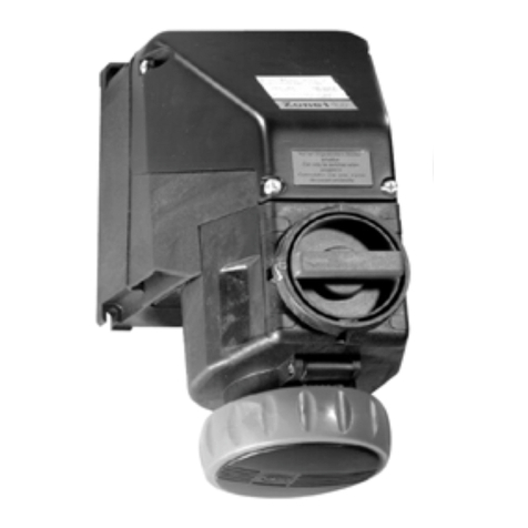
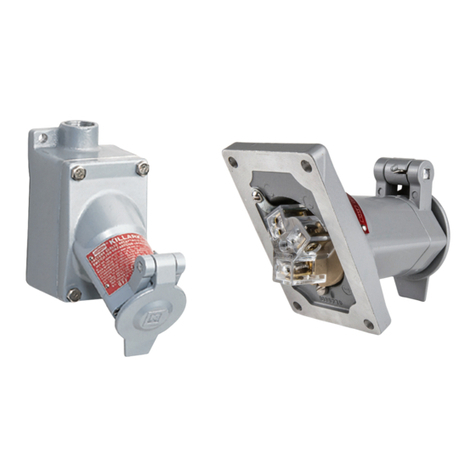
THE ACCEPTOR SERIES "UGP" & "UGP(QW)" PLUGS
IMPORTANT: These plugs must be installed by trained,
qualified and competent personnel.
NOTE: All installations must comply with applicable local
and/or national electrical codes, as well as safety practices
for this type of equipment.
WARNING: Electrical power must be OFF during
installation. Disconnect supply circuit and Lock Out.
CAUTION: To reduce the risk of ignition of hazardous
atmospheres, do not use in Class II, Group F locations that
contain electrically conductive dusts.
Before install, check the carton label and product
nameplate to be sure you have the correct type.
DIRECTIONS FOR INSTALLATION
UGP : For use with Killark Type "UGR" receptacles and
other receptacles specified on Form No. K1092, also
provided with this product.
1.) Loosen (2) screws (with lockwashers) "A" in plug face
and pull Plug Contact Assembly (with gasket) from Plug
Body. NOTE: Fiber insulator should remain in Plug Body.
Loosen (2) screws "B" at back of plug to remove Cord
Clamp Cover.
2.) Strip cord jacket and wire insulation from #12 or #14 (as
required) AWG type S, SO, ST or STO cord, per strip gage
shown below. Cord diameter must be .540 to .635 inches.
Do not use cord of smaller diameter.
3.) Loosen (2) Cord Clamp screws "C" and feed cord,
prepared end first, through Cord Clamp Cover and Cord
Clamps. Lubricate approximately 1-1/2" of prepared end of
cord jacket with a suitable lubricant and insert cord through
sealing Grommet into Plug Body.
4.) Loosen all (3) Wire Terminal screws and insert wire into
proper terminals: Green lead (Ground) to terminal by Green
mark; White (Neutral) lead to terminal by White mark (125V
only); Black and/or Red [Line lead(s)] to unmarked
terminal(s). Hand tighten terminal screws to 8 in.lbs.
torque.
5.) Check to make sure fiber insulator is installed in Plug
Body. Properly align the Plug Contact Assembly (with
gasket) and slide Plug Body down over contact assembly
until seated. Insert (2) screws and lockwashers "A" and
tighten to 8 in.lbs. torque.
6.) Tighten Cord Clamp screws "C", alternating between
them to equalize torque. Tighten until clamps firmly grip
cord to prevent movement.
7.) Position Cord Clamp Cover; insert and tighten (2)
screws "B". Check for ground continuity between ground
post and plug body. Check for discontinuity between live
spade contacts and/or plug body.
UGP [QW model, side 2]
P/N KIL00921377 FORM NO. K1377 R11/17 ECO-7-028-17 Side 2 of 2
DIRECTIONS FOR INSTALLATION
UGP(QW) : For use with Killark Type "UGR"
receptacles and other receptacles specified on Form No.
K1092, also provided with this product.
1.) Loosen (2) screws "A" in plug face and pull Plug
Contact Assembly (with gasket) from the Plug Body.
Remove Insulator Assembly from Plug Body.
2.) Strip cord jacket and wire insulation from #10, #12 or
#14 (as required) AWG type S, ST, STO, SO, SOO, SOW
or SOOW cord per strip gage on back of Plug Contact
Assembly or this sheet. Do not use cord smaller than #14
AWG. NOTE: UGP-QW devices are rated for 20 amps;
#10 wire is appropriate only for voltage drop applications.
3.) Lubricate approximately 1-1/2" of prepared end of cord
jacket with a suitable lubricant and insert cord through
Grommet; into Plug Body. Loosen (2) Cord Clamp screws
"B" on the Insulator Assembly and feed cord, prepared end
first, through the Cord Clamps and the Insulator Assembly.
4.) Loosen all (3) Terminal Contact Screws and insert wire
through the Wiring Entrance holes, into proper terminals:
Green lead (Ground) to terminal with ground mark & Green
screw head; White (Neutral) lead to terminal with Silver
screw head (125V only); Black and/or Red [Line lead(s)] to
terminal(s) with Brass screw head. Hand tighten terminal
screws to 8 in.lbs. torque.
5.) Properly align the Plug Contact Assembly (with gasket)
and slide the Insulator Assembly down over Contact
Assembly until seated. Tighten Cord Clamp screws "B",
alternating between them to equalize torque. Tighten until
clamps firmly grip cord to prevent movement. (16 in.lbs.
torque recommended)
6.) Properly align Insulator assembly with Plug Body and
slide Plug Body down over Insulator assembly until seated.
Tighten (2) screws in plug face to 8 in.lbs. torque.
7.) Check for ground continuity between ground post and
plug body. Check for discontinuity between live spade
contacts and/or plug body.
OPERATIONAL DATA (with Killark type "UGR" receptacle)
1) Lift receptacle door and insert plug all the way into the
receptacle.
2) Turn plug to clockwise limit (45°). This closes internal
contacts and completes circuit.
3) Release plug. Plug will move outward to "LOCK"
position. Check by trying to turn plug without pushing
inward; plug should not turn.
4) To remove plug, push plug inward and turn to counter-
clockwise limit (45°). Pull plug straight out.
MAINTENANCE DATA: These plugs require no
maintenance other than a periodic cleaning and a check for
damage and/or loose fasteners. Also, check cord for
damage and/or wear. This should be performed on a
regular basis, determined by the environment and usage.
WARNING: Disconnect and Lock Out supply circuit before
starting maintenance work.
1) To clean plug it is recommended that a soft, non-
metallic bristle brush be used.
2) Check tightness of all accessible screws.
3) Inspect the entire assembly (including cord) for damage
and/or wear. Consult Killark factory for availability of
replacement parts and discontinue use of the equipment
until repairs are made.
UGP(QW)
Technical information, advice and recommendations contained in these
documents is based on information that Killark believes to be reliable. All
the information and advice contained in these documents is intended for
use by persons having been trained and possessing the requisite skill and
know-how and to be used by such persons only at their own discretion and
risk. The nature of these instructions is informative only and does not cover
all of the details, variations or combinations in which this equipment may be
used, its storage, delivery, installation, check out, safe operation and
maintenance. There are no warranties, expressed or implied, except that
all goods shall conform to their description, subject however to commercial
tolerances and variations.
All sales are made on the express understanding that there are no
express warranties other than those contained in a specific agreement
between Seller and Buyer and that there are no implied warranties that the
goods shall be merchantable, nor are there any warranties which extend
beyond the description on the face hereof. In the event of the breach of
any warranty or alleged breach of any warranty by Killark, the Buyer shall
not be entitled to consequential or incidental damages. The obligation of
Killark under its warranty shall be limited to repairing or replacing FOB
Killark's plant or allowing credit at Killark's option, any part or parts which
may prove to be thus defective, provided the Buyer(s) gives Killark prompt
notice of the defect or defects. It is expressly agreed and understood that
this remedy of repair or replacement or credit at Killark's option is the
exclusive remedy of the Buyer of this product. Since conditions of use of
the product are outside of the care, custody and control of Killark, the
purchaser should determine the suitability of the product for his intended
P/N KIL00921377 FORM NO. K1377 R11/17 ECO-7-028-17 Side 3 of 2
use, and assumes all risk and liability whatsoever in connection therewith.

This manual suits for next models

1

Other Hubbell Accessories manuals

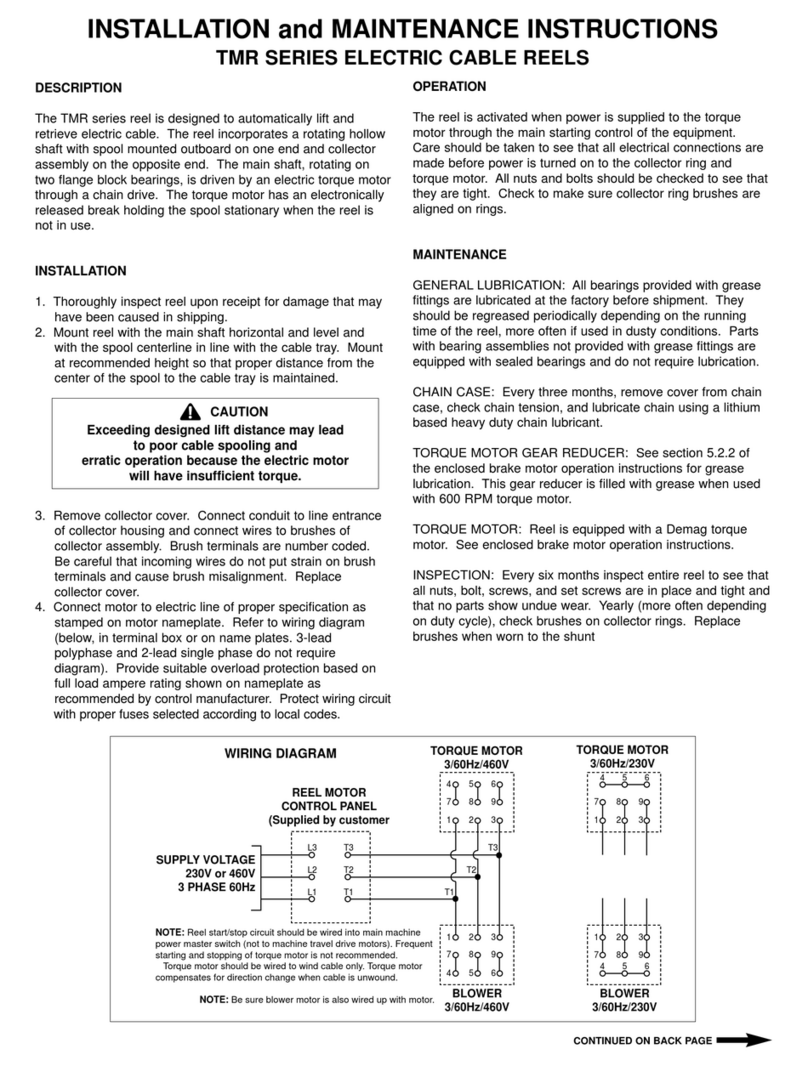
Hubbell Gear Drive Electric Cable Reels S-28 User manual

Hubbell

Hubbell Gear Drive Electric Cable Reels S-28 User manual

Hubbell H-MOSS User manual

Hubbell

Hubbell H-MOSS User manual

Hubbell NX Distributed Intelligence NXSMP-LMO User manual

Hubbell

Hubbell NX Distributed Intelligence NXSMP-LMO User manual

Hubbell Direct Drive Electric Cable Reels S-32 User manual

Hubbell

Hubbell Direct Drive Electric Cable Reels S-32 User manual

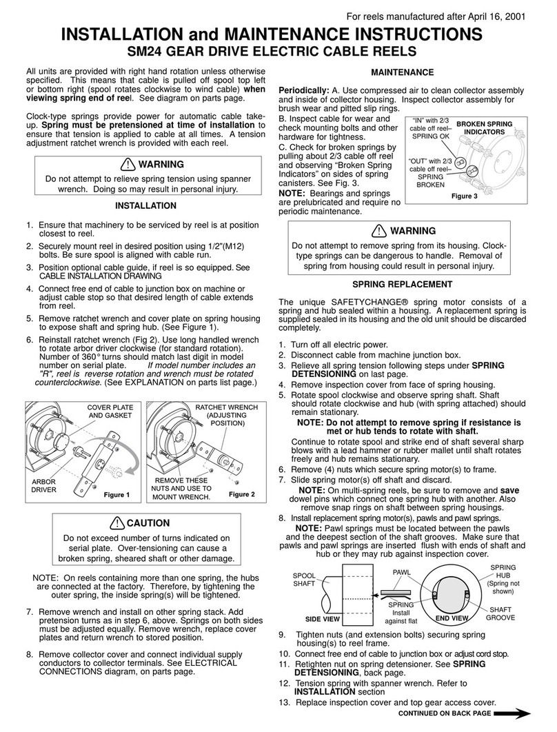
Hubbell Gear Drive Electric Cable Reels SM-24 User manual

Hubbell

Hubbell Gear Drive Electric Cable Reels SM-24 User manual

Hubbell H-MOSS ATD500C User manual

Hubbell

Hubbell H-MOSS ATD500C User manual

Hubbell H-MOSS ATP1274 User manual

Hubbell

Hubbell H-MOSS ATP1274 User manual

Hubbell Dual Hose Reel R-35 User manual

Hubbell

Hubbell Dual Hose Reel R-35 User manual

Hubbell Gear Drive Electric Cable Reels SM21 User manual

Hubbell

Hubbell Gear Drive Electric Cable Reels SM21 User manual

Hubbell AFBS1R4 Series User manual

Hubbell

Hubbell AFBS1R4 Series User manual

Hubbell INSULGRIP HBL4100RS1W Owner's manual

Hubbell

Hubbell INSULGRIP HBL4100RS1W Owner's manual

Hubbell Direct Drive Electric Cable Reels S-21 User manual

Hubbell

Hubbell Direct Drive Electric Cable Reels S-21 User manual

Hubbell Direct Drive Electric Cable Reels MMD32 User manual

Hubbell

Hubbell Direct Drive Electric Cable Reels MMD32 User manual

Hubbell WS Series User manual

Hubbell

Hubbell WS Series User manual

Hubbell KILLARK ACCEPTOR UGR Series Instruction Manual

Hubbell

Hubbell KILLARK ACCEPTOR UGR Series Instruction Manual

Hubbell H-MOSS WS Series User manual

Hubbell

Hubbell H-MOSS WS Series User manual

Hubbell KILLARK VSI30 Series Instruction Manual

Hubbell

Hubbell KILLARK VSI30 Series Instruction Manual

Hubbell WS2001NS Series User manual

Hubbell

Hubbell WS2001NS Series User manual

Hubbell LightOWL LODT Manual

Hubbell

Hubbell LightOWL LODT Manual

Hubbell Gear Drive Electric Cable Reels MMD21 User manual

Hubbell

Hubbell Gear Drive Electric Cable Reels MMD21 User manual

Hubbell NX Distributed Intelligence NXSMP-OMNI User manual

Hubbell

Hubbell NX Distributed Intelligence NXSMP-OMNI User manual

Hubbell BTSMP-HMO User manual

Hubbell

Hubbell BTSMP-HMO User manual

Hubbell LightHawk LHMT User manual

Hubbell

Hubbell LightHawk LHMT User manual

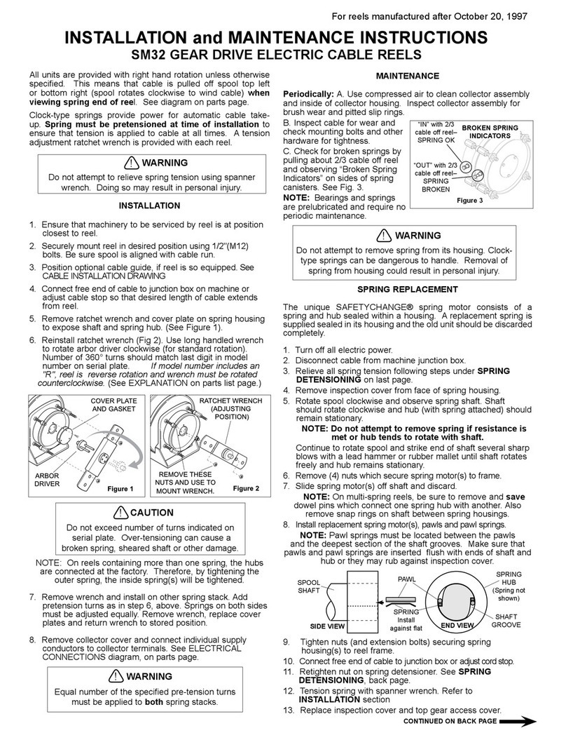
Hubbell Gear Drive Electric Cable Reels SM32 User manual

Hubbell

Hubbell Gear Drive Electric Cable Reels SM32 User manual

Popular Accessories manuals by other brands

IKEA TRADFRI E1702 manual

IKEA

IKEA TRADFRI E1702 manual

Amphenol Temposonics T Series Operation manual

Amphenol

Amphenol Temposonics T Series Operation manual

HYTROL NBEZ Installation and maintenance manual

HYTROL

HYTROL NBEZ Installation and maintenance manual

ASM posirot PRAS Series Installation and operation manual

ASM

ASM posirot PRAS Series Installation and operation manual

Denver PSO-20007 quick start guide

Denver

Denver PSO-20007 quick start guide

Zinc ZN25152 User instructions

Zinc

Zinc ZN25152 User instructions

Promate Force-10 user guide

Promate

Promate Force-10 user guide

Clevertouch WL10A-G user manual

Clevertouch

Clevertouch WL10A-G user manual

Novalynx 200-WS-02 Series user manual

Novalynx

Novalynx 200-WS-02 Series user manual

Simply Automated UPB URD manual

Simply Automated

Simply Automated UPB URD manual

inventum HN5211L instruction manual

inventum

inventum HN5211L instruction manual

KROHNE OPTIFLUX 2000 quick start

KROHNE

KROHNE OPTIFLUX 2000 quick start

MAMAC SYSTEMS TE-701 technical information

MAMAC SYSTEMS

MAMAC SYSTEMS TE-701 technical information

Baumer OBDM 12N6910/S35A manual

Baumer

Baumer OBDM 12N6910/S35A manual

ELRO DVC040IP manual

ELRO

ELRO DVC040IP manual

ZMODO ZM-CJAED quick start guide

ZMODO

ZMODO ZM-CJAED quick start guide

Panasonic TYTP10E operating instructions

Panasonic

Panasonic TYTP10E operating instructions

Denver Electronics CRL-300 user manual

Denver Electronics

Denver Electronics CRL-300 user manual

manuals.online logo
manuals.online logoBrands
  • About & Mission
  • Contact us
  • Privacy Policy
  • Terms and Conditions

Copyright 2025 Manuals.Online. All Rights Reserved.