Chatsworth Products A2 User manual

RMR WALL-MOUNTENCLOSURES
IIS-737100, 09/16/16, Rev. 1, CPI/SJG
800-834-4969 (USA & Canada) • www.chatsworth.com • techsupport@chatsworth.com
For international phone numbers, see our website or contact CPI Tech Support.
This drawing contains proprietary and confidential information and is protected by U.S. and international law. Unauthorized reproduction, disclosure or use of the drawing
or the information therein is expressly forbidden except as agreed to in writing by Chatsworth Products, Inc.
Page 1 of 8
Installation Instructions
Safety Information
WARNING: Improper use of this product or failure to follow
these instructions may result in equipment damage, personal
injury, or death. Read and understand all instructions for proper
installation and use of this product.
WARNING: Before loading equipment in the cabinet, be sure all
parts and hardware are properly installed and tightened.
Intended Use
Install RMR Wall-Mount Enclosures only in indoor, nonhazardous locations
such as manufacturing environments and warehouse distribution centers.
The enclosures are rated for NEMA Type 12 and IP 55 protection, which
provides protection against dirt and dust, light spray with noncorrosive liquid
and penetration from oil seepage. Use indoors only; do not use outdoors.
Use RMR Wall-Mount Enclosures for information technology and
telecommunications equipment, systems control automation electronics
and/or instrumentation. Allow only qualified service personnel to use this RMR
Wall-Mount Enclosure.
RMR Fixed Wall-Mount
(A2 Model)
RMR Swing Wall-Mount
(A3 Model)

RMR WALL-MOUNTENCLOSURES
Page 2 of 8
Installation Instructions
Assembly Sequence –Wall Mounting
Before installing the cabinet, ensure that the wall or mounting surface has
sufficient strength to support the cabinet and the expected cabinet payload.
The mounting surface must also be flat and extend beyond the top, bottom,
left, and right edges of the cabinet.
RECOMMENDED: Use RMR Quick Wall-Mounting Kit (ordered separately)
for quick and easy mounting of RMR Wall-Mount Enclosures.
See IIS-737045-001 for details.
Jump to “Assembly Sequence – Equipment Rails” (page 4) if using RMR
Quick Wall-Mounting Kit
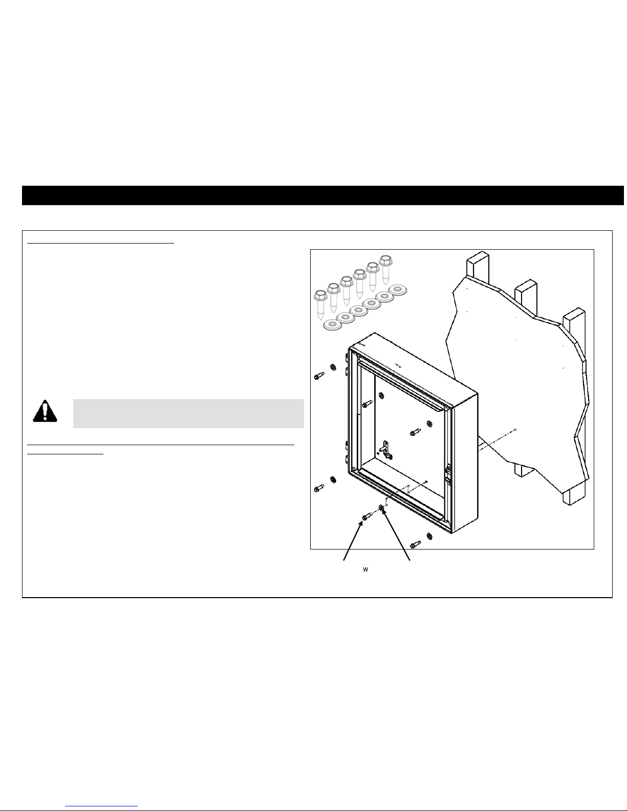
Assembly Sequence –Standard Mounting Kit
Tools Required
M13 Socket Driver
Included Hardware
(6) Sealing Washer
(6) M8x40 Lag Screw
Note: For A2 model RMR Fixed Wall-Mount - Start on step 2. Skip thesesteps and
jump to “Assembly Sequence – Equipment Rails” (page 4) if using RMR Quick Wall-
Mounting Kit.
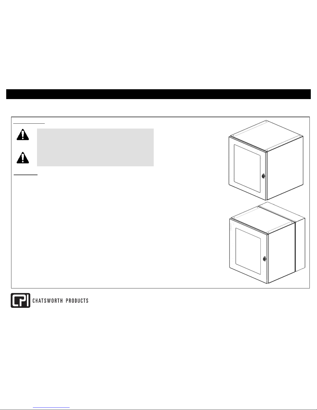
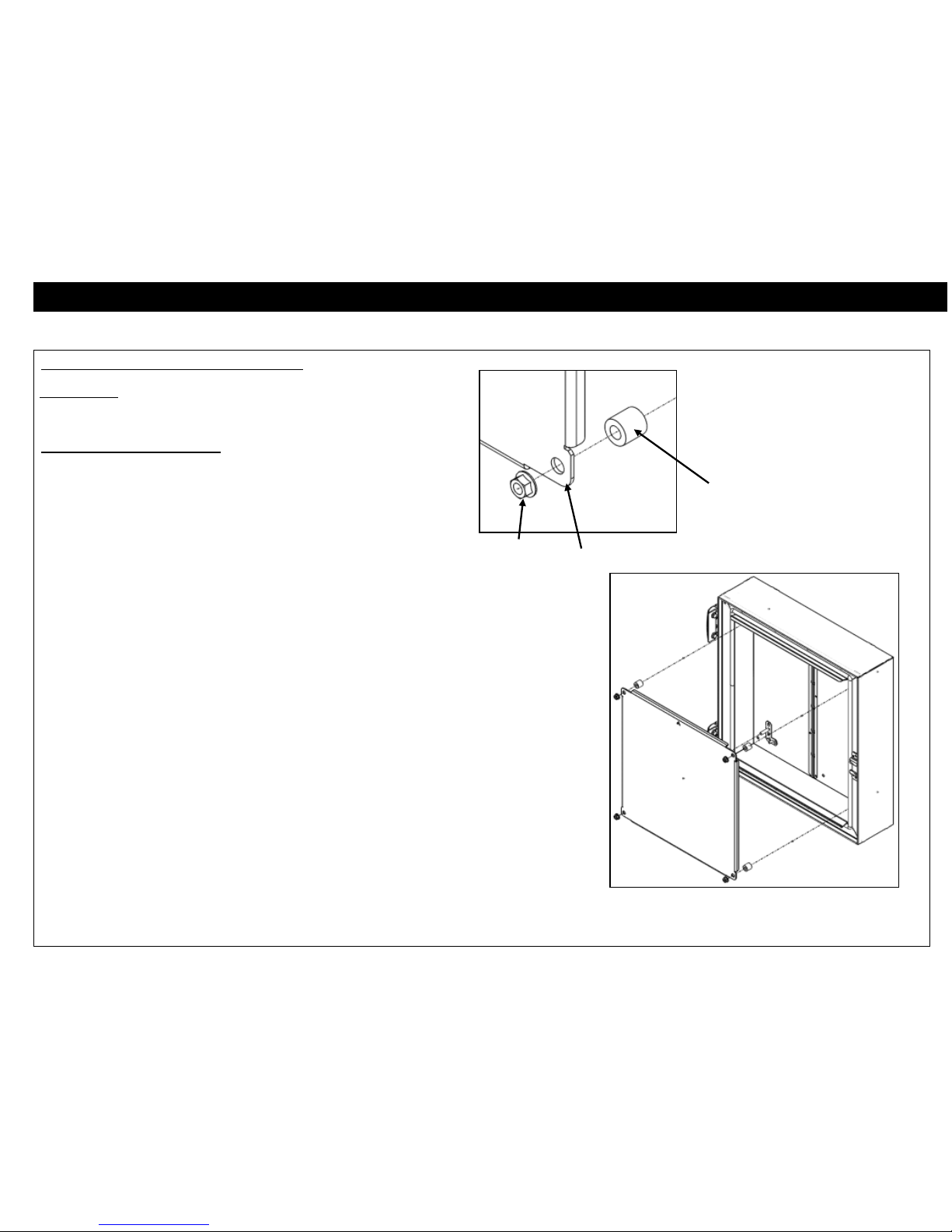
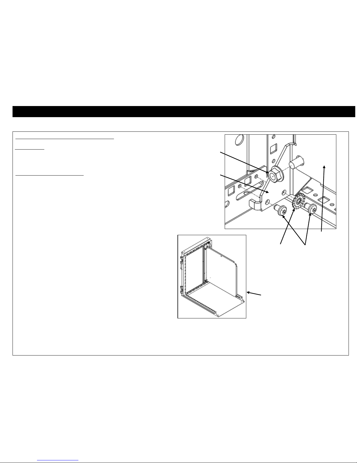
Step 1: Separate Center Chassis from Rear Chassis-
For A3 models, RMR Swing Wall-Mount Enclosure only
1. Determine which side the cabinet will hinge from. The cabinet is
shown with the hinge on the left side. Invert the cabinet to position
the hinge on the right side.
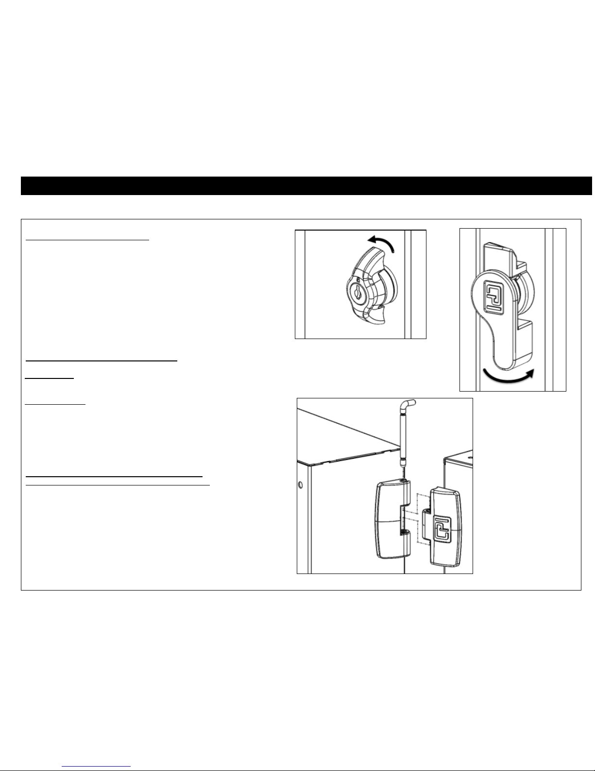
2. Rotate front door latch counterclockwise to open Front Door to gain
access to center chassis latch.
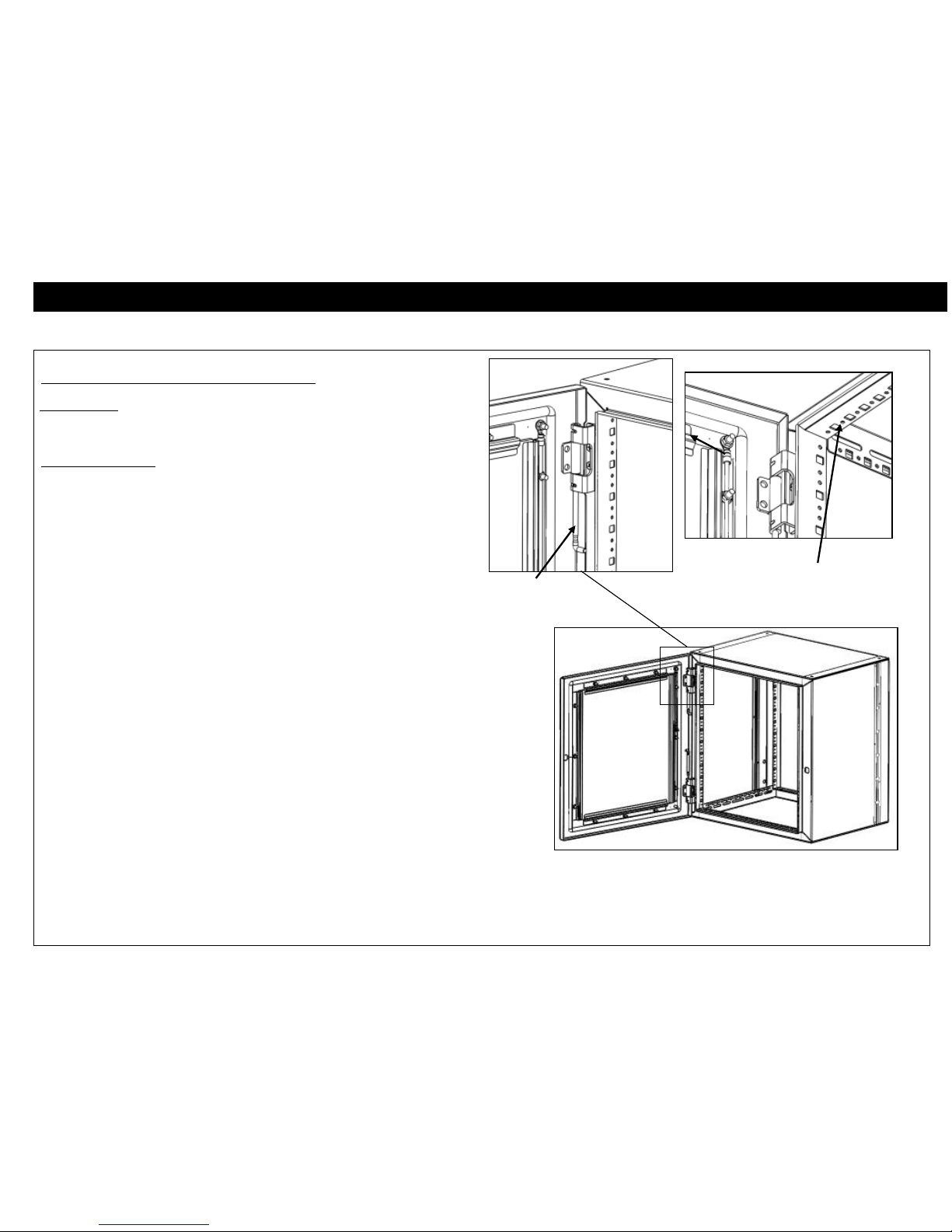
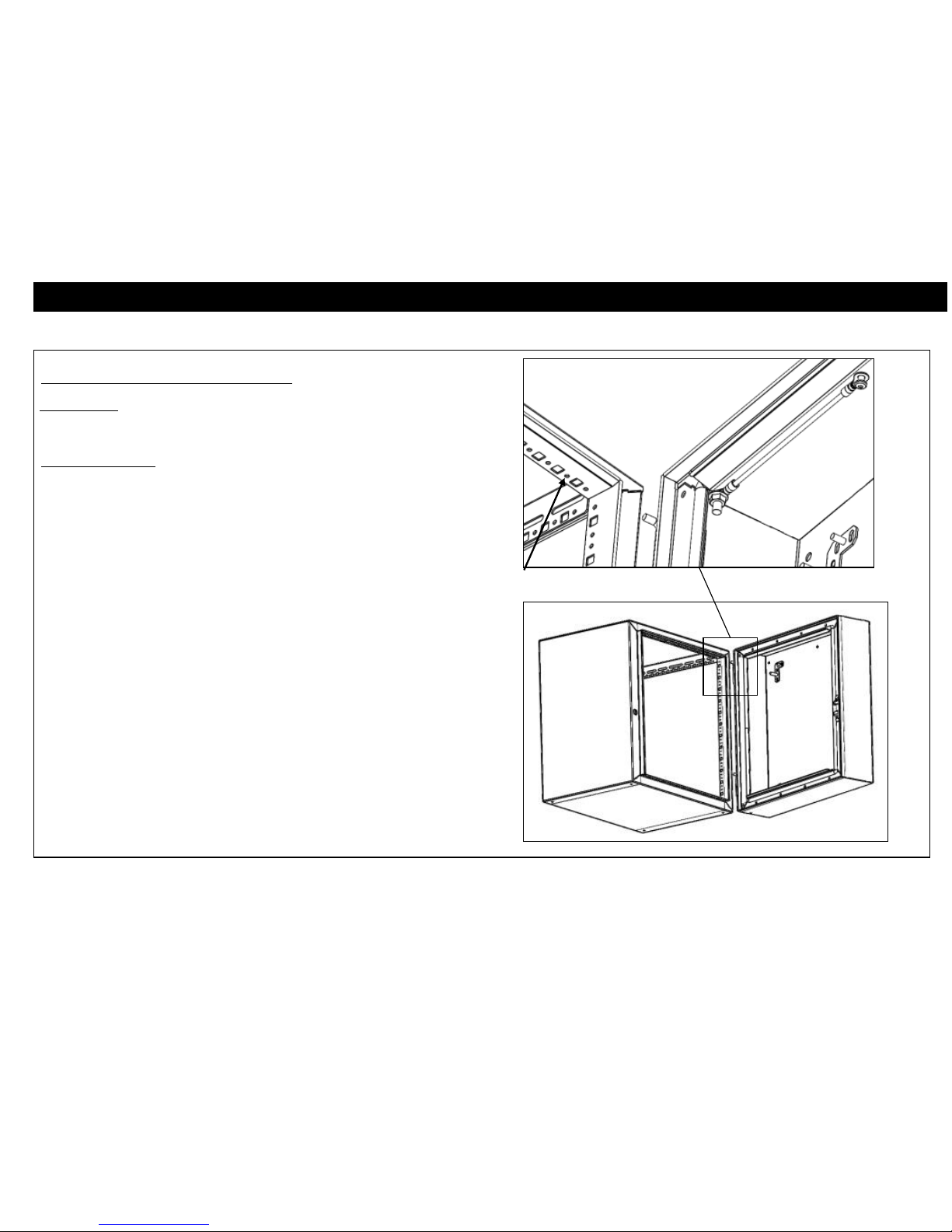
3. Rotate center chassis latch(es) counter-clockwise and swing open
center chassis 120 degrees.
4. Pull out hinge pins to separate center chassis from rear chassis.

RMR WALL-MOUNTENCLOSURES
Page 3 of 8
Installation Instructions
Step 2: Mounting Rear Chassis to the wall
5. Determine desired location of cabinet on wall.
6. Place rear chassis flush against wall at desired location.
7. Use the rear chassis as a template and drill pilot holes for the two top
corner lag screws.
Note: The lag screws are intended to go through ¾” (19mm) plywood back-
board and then into wood wall studs. For masonry or other surfaces, the
installer must provide appropriate hardware.
8. Install left lag screw with washer through rear chassis into wall.
9. Rotate rear chassis until level.
10. Install right lag screw with washer through rear chassis into wall.
11. Drill pilot holes for remaining lag screws.
12. Install remaining lag screws with washers through rear chassis into
wall.
WARNING: Rear chassis must be secured to the wall with 6 lag
screws. Do not attach center chassis until all 6 lag screws are
installed.
Step 3: Attach Center Chassis to Rear Chassis –For A3 model, Swing Wall-
Mount Enclosure only
13. Lift center chassis to realign cabinet hinges.
14. Reinsert hinge pins to join center chassis to rear chassis.
M8 Lag Screw
Sealing Washer
(Metal Side under Nut)

RMR WALL-MOUNTENCLOSURES
Page 4 of 8
Installation Instructions
Assembly Sequence –Equipment Rails
Tools Required
M10 Socket Driver
Step 1: Equipment Rail Adjustment
15. Loosen nut. Slide rail to new position, or remove hardware to locate
to a different slot.
16. Install round head bolt through star washer and slot in mounting
flange.
17. Install rail over bolt.
18. Attach nut and tighten.(Torque 168 IN-LB [19.0 N-M])
Round
Head Bolt
M6 Nut
Star
Washer

RMR WALL-MOUNTENCLOSURES
Page 5 of 8
Installation Instructions
Assembly Sequence –Rear Back Plate Mounting
Tools Required
M13 Socket Driver
Step 1: Rear Back Plate Mounting
1. Install plastic spacers over M8 studs in cabinet
2. Install back plane (arrow at top) onto M8 studs
3. Attach nuts and tighten. (torque 168 IN-LB [19.0 N-M])
Plastic
Spacer
M8 Nut
Back Plane

RMR WALL-MOUNTENCLOSURES
Page 6 of 8
Installation Instructions
Assembly Sequence –Adjustable Mounting Plate
Tools Required
M13 socket driver
T25 Torx screw driver
Step 1: Adjustable Mounting Plate
1. Insert tab on mounting bracket into square hole
2. Attach with two M5.5 Torx screws with star washer
(Torque 44 IN-LB [5 N-M]).
3. Insert Adjustable Mounting Plate onto M8 studs on mounting brackets
(arrow on top)
4. Secure with M8 Nuts (Torque 168 IN-LB [19.0 N-M])
M5.5
Torx Screw
M8 Nut
Back Plane
Star
Washer
Mounting
Bracket
Inside Cabinet
Top and Sides hidden
for clarity

RMR WALL-MOUNTENCLOSURES
Page 7 of 8
Installation Instructions
Assembly Sequence –Door Assembly and Bonding
Tools Required
T25 Torx screw driver
Step 1: Door Bonding
1. Align hinges on door with hinges on cabinet.
2. Press hinge pins through door hinges until fully seated. (detent
engaged)
3. Attach ground wire to circular hole using M5.5 Torx panhead screw
(torque 44 IN-LB [5 N-M]).
Hinge Pin
Shown unseated
Attach
Ground Wire
to hole

RMR WALL-MOUNTENCLOSURES
Page 8 of 8
Installation Instructions
Assembly Sequence –Center Chassis Bonding
Tools Required
T25 Torx screw driver
Step 1: Door Bonding
1. Attach ground wire to circular hole using M5.5 Torx panhead screw
(torque 44 IN-LB [5 N-M]).
Attach Ground
Wire to hole
This manual suits for next models
1
Table of contents
Popular Indoor Furnishing manuals by other brands

Whalen Furniture
Whalen Furniture Golden Oak Zeta Rolling File ZTRF Instruction booklet

Sunny
Sunny Dual Top Table C052.002.00 user manual

Girsberger
Girsberger Kyra quick start guide

Furn Mill
Furn Mill BOSTON SLIDING BED Assembly instructions

Silver Fox
Silver Fox 51000 quick start guide

Crate&Barrel
Crate&Barrel Verge Series Assembly manual

The Land of Nod
The Land of Nod Topside Bunk Bed Assembly instructions

Forte
Forte RIBS13411 Assembling Instruction

Coaster
Coaster 204354 Assembly instructions

Lorell
Lorell LLR44216 instructions

Kimball Office
Kimball Office Transcend Master Packet Complete Series Assembly instructions

Style selections
Style selections 1007VA-24-210 manual