Chattanooga Group ERGOSTYLE FX 5820 User manual
© 2006 Encore Medical, L.P.
Model 5820- Manual Drops
Model 5822- Auto Drops
Applies to Serial numbers 1000 and above
SERVICE MANUAL
ISO 13485 Certified
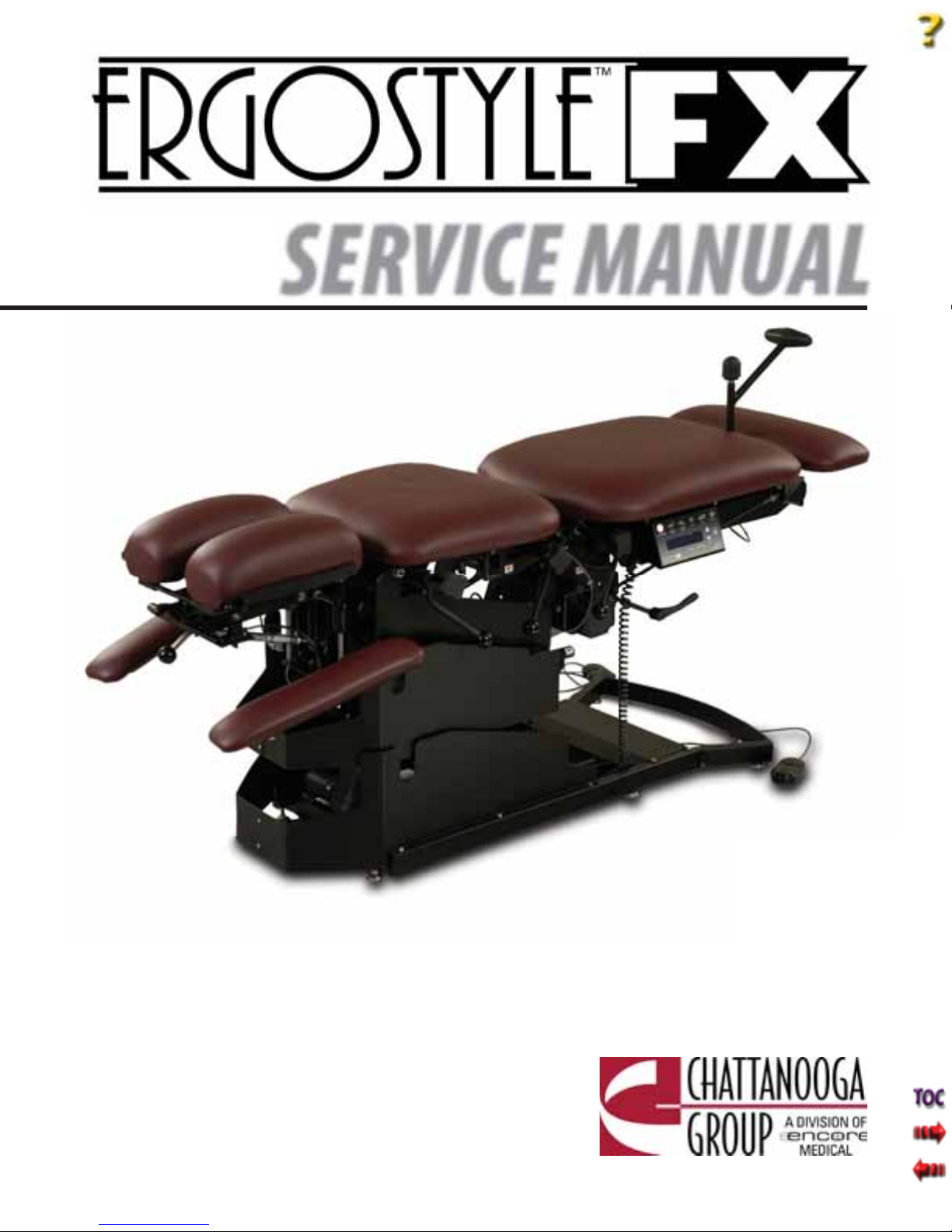
Ergostyle ™ FX Tables
FOREWORD . .. .. .. .. .. .. .. .. .. .. .. .. .. .. .. .. .. .. .. .. .. .. .. 1
1 SAFETY PRECAUTIONS.. .. .. .. .. .. .. .. .. .. .. .. .. .. .. 2
1.1 PRECAUTIONARY DEFINITIONS .. .. .. .. .. .. .. ..2
1.2 PRECAUTIONARY INSTRUCTIONS . .. .. .. .. .. ..2
2 NOMENCLATURE . .. .. .. .. .. .. .. .. .. .. .. .. .. .. .. .. .. .. 5
2.1 ERGOSTYLE FX TABLE
EXTERNAL COMPONENTS. .. .. .. .. .. .. .. .. .. .. ..5
3 SPECIFICATIONS .. .. .. .. .. .. .. .. .. .. .. .. .. .. .. .. .. .. .. 6
3.1 SPECIFICATIONS . .. .. .. .. .. .. .. .. .. .. .. .. .. .. .. .. ..6
4 TROUBLESHOOTING. .. .. .. .. .. .. .. .. .. .. .. .. .. .. .. ..7
4.1 ERGOSTYLE FX TABLE
TROUBLESHOOTING .. .. .. .. .. .. .. .. .. .. .. .. .. .. ..7
4.2 VISUAL INSPECTION .. .. .. .. .. .. .. .. .. .. .. .. .. .. ..8
4.3 GROUND RESISTANCE TEST. .. .. .. .. .. .. .. .. .. ..8
4.4 LEAKAGE TESTS .. .. .. .. .. .. .. .. .. .. .. .. .. .. .. .. .. ..8
4.5 POWER ON/OFF TEST. .. .. .. .. .. .. .. .. .. .. .. .. .. ..9
4.6 PATIENT INTERRUPT SWITCH TEST .. .. .. .. .. ..9
4.7 AUTO FLEXION AND AUTO DROP TESTS. .. .. .9
5 REMOVAL AND REPLACEMENT.. .. .. .. .. .. .. .. .. 10
5.1 POWER SUPPLY
REMOVAL AND REPLACEMENT .. .. .. .. .. .. .. 10
5.2 DAUGHTER BOARD REMOVAL AND
REPLACEMENT MANUAL TABLE ONLY .. 12
5.3 DRIVER BOARD
REMOVAL AND REPLACEMENT .. .. .. .. .. .. .. 13
5.4 CONTROL BOARD ASSEMBLY
REMOVAL AND REPLACEMENT
AUTO FLEXION ONLY. .. .. .. .. .. .. .. .. .. .. .. .. 14
5.5 MOTOR REMOVAL AND REPLACEMENT.. .. 15
5.6 DROP ASSEMBLY
REMOVAL AND REPLACEMENT .. .. .. .. .. .. .. 17
6- CALIBRATION .. .. .. .. .. .. .. .. .. .. .. .. .. .. .. .. .. .. .. .. ..18
6.1 FLEXION CALIBRATION
AUTO TABLES ONLY.. .. .. .. .. .. .. .. .. .. .. .. .. .. 18
7 PARTS . .. .. .. .. .. .. .. .. .. .. .. .. .. .. .. .. .. .. .. .. .. .. .. .. 19
7.1 CONTROL BOARD ASSEMBLY. .. .. .. .. .. .. .. .. 19
7.2 DROPS .. .. .. .. .. .. .. .. .. .. .. .. .. .. .. .. .. .. .. .. .. .. .. 20
7.3 HEAD PIECE ASSEMBLY .. .. .. .. .. .. .. .. .. .. .. .. 21
8- SCHEMATICS. .. .. .. .. .. .. .. .. .. .. .. .. .. .. .. .. .. .. .. .. ..22
9 WARRANTY .. .. .. .. .. .. .. .. .. .. .. .. .. .. .. .. .. .. .. .. .. 27
TABLE OF CONTENTS
1
Ergostyle ™ FX Tables
Read, understand, and follow the Safety Precautions and all other information contained in this
manual.
This manual contains the necessary safety and field service information for those field service
technicians, certified by Chattanooga Group, to perform field service on the Ergostyle FX Tables.
At the time of publication, the information contained herein was current and up-to-date. However,
due to continual technological improvements and increased clinical knowledge in the field of
traction therapy, as well as Chattanooga Group’s policy of continual improvement, Chattanooga
Group reserves the right to make periodic changes and improvements to their equipment and
documentation without any obligation on the part of Chattanooga Group.
It is the sole responsibility for certified field technicians to stay informed and trained in the latest
technology utilized in the Ergostyle FX Tables by Chattanooga Group. From time to time, as
significant improvements are incorporated, service bulletins will be produced and made available
on our web site (chattgroup.com) in lieu of reprinting a complete manual prematurely. These service
bulletins will provide updated service information and technological improvements to the Ergostyle
FX Tables for use by certified service technicians.
Due to the complex nature of the technology utilized by Chattanooga Group, the recommended
troubleshooting techniques are to determine “Bad Board” and board replacement only. No board
component level troubleshooting is recommended, nor will information or parts be supplied by
Chattanooga Group.
Any board component level troubleshooting performed will be at the sole risk and liability of the
certified field service technician performing such troubleshooting techniques. Performance of such
techniques may render the warranty null and void.
Ergostyle FX Tables are prescription devices to be used only under the supervision of and by the
order of a physician or other licensed health care provider.
FOREWORD
©2006 Encore Medical Corporation or its affiliates, Austin, Texas, USA. Any use of editorial, pictorial, or layout composition of this publication without express written consent
from the Chattanooga Group of Encore Medical, L.P. is strictly prohibited. This publication was written, illustrated, and prepared for print by the Chattanooga Group of
Encore Medical, L.P.
2
Ergostyle ™ FX Tables
1 SAFETY PRECAUTIONS
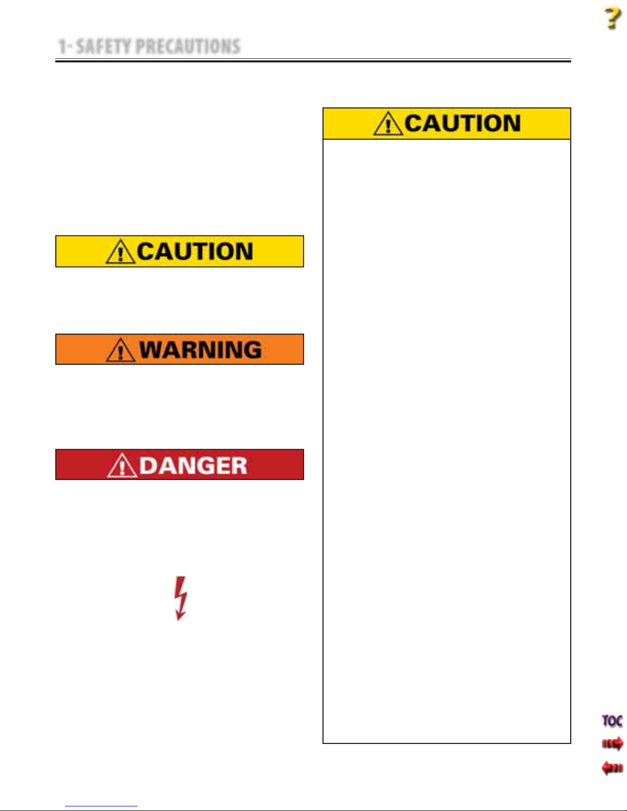
The precautionary instructions found in this
section and throughout this manual are indicated
by specific symbols. Understand these symbols
and their definitions before operating this
equipment. The definition of these symbols are as
follows:
Text with a “CAUTION” indicator will explain
possible safety infractions that could have the
potential to cause minor to moderate injury or
damage to equipment.
Text with a “WARNING” indicator will explain
possible safety infractions that will potentially
cause serious injury and equipment damage.
Text with a “DANGER” indicator will explain
possible safety infractions that are imminently
hazardous situations that would result in death
or serious injury.
Text with a “DANGEROUS VOLTAGE” indicator
serves to inform the technician of possible
hazards resulting in the electrical charge
disbursement from certain components if
handled or serviced improperly.
Throughout this manual, “NOTE” may be found.
These Notes are helpful information to aid in
the particular area or function being described.
1.1 PRECAUTIONARY DEFINITIONS
A. Caution
B. Warning
C. Danger
D. Dangerous Voltage
E. NOTE
1.2 PRECAUTIONARY INSTRUCTIONS
A. Cautions
Read, understand, and practice all precautionary
instructions found in this manual. Know the
limitations and hazards associated with use of
these tables. Observe the precautionary and
operational decals placed on the unit.
Do not use accessories other than those supplied
with the unit or recommended by Chattanooga
Group. The safety of other products has not been
established, and their use could result in injury to
the patient.
This unit should be transported and stored in
temperatures between 0°F and 140°F (-18°C
and 60°C) to prevent damage to the unit or its
components.
DO NOT operate this unit in an environment
where other devices are being used that
intentionally radiate electromagnetic energy in
an unshielded manner. Portable and mobile RF
communications equipment can affect Medical
Electrical Equipment.
This unit generates, uses, and can radiate radio
frequency energy and, if not installed and
used in accordance with the instructions, may
cause harmful interference to other devices
in the vicinity. However, there is no guarantee
that interference will not occur in a particular
installation. Harmful interference to other
devices can be determined by turning this (table,
unit, device, etc.) on and off. Try to correct the
interference using one or more of the following:
reorient or relocate the receiving device, increase
the separation between the equipment, connect
the equipment to an outlet on a different
circuit from that which the other device(s) are
connected and consult the Chattanooga Group
Service Department for help.
The unit should be routinely checked before each
use to determine all controls function normally.
Handle the unit with care. Inappropriate handling
of the unit may adversely affect its characteristics.
Before each use, inspect the table cables and
hoses for wear. Prolonged wear on these
components may cause them to break, which
may cause sudden release of pneumatic pressure.
Test the Patient Switch before each use for power
operation.
•
•
•
•
•
•
•
•
•
3
Ergostyle ™ FX Tables
1 SAFETY PRECAUTIONS
1.2 PRECAUTIONARY INSTRUCTIONS (continued)
Do not remove the covers. This may cause unit
damage, malfunction, electrical shock, fire, or
personal injury. There are no user-serviceable parts
inside the unit. If a malfunction occurs, discontinue
use immediately, disconnect the Mains Power Cord
from the outlet, and consult the dealer for repair
service.
Do not use sharp objects such as a pencil point
or ballpoint pen to operate the buttons on the
Control Panel as damage may result.
Do not permit any foreign materials or liquids
to enter the unit. Take care to prevent any
foreign materials including, but not limited to,
inflammables, water, and metallic objects from
entering the unit. These may cause unit damage,
malfunction, electrical shock, fire, or personal
injury.
Do not disassemble, modify, or remodel the
unit or accessories. This may cause unit damage,
malfunction, electrical shock, fire, or personal
injury.
Do not use the table near devices such as X-ray
units or diathermy units. These units may emit
high frequency noise that may affect the operation
of the unit.
Failure to use and maintain the table and its
accessories in accordance with the instructions
outlined in this manual will render the warranty
void.
The tool, lubrication, and locking compound
requirements listed are critical to component
maintenance, removal and replacement.
The hardware, bolts, nuts, and screws used to
assemble the Ergostyle FX are SAE. Therefore, it will
be necessary to obtain SAE tools for removal and
replacement of components.
The table base should never be operated in an “out
of level” position to the horizontal/ground plane
greater than 5°.
Always use both hands when changing the angle
of any section, up or down.
•
•
•
•
•
•
•
•
•
•
Never place your hands or feet near the working
mechanism of the table when making any and all
adjustments to height or table sections.
Use only accessories that are specially
designed for the ErgoStyle FX table. Do not use
accessories manufactured by other companies
on the ErgoStyle FX. Chattanooga Group is
not responsible for any consequence resulting
from using products manufactured by other
companies. The use of other accessories or cables
may result in increased emissions or decreased
immunity of the ErgoStyle FX.
Do not sit or allow patients to sit on the Head
Section, Flexion Section, or Extending Ankle Rest
of the table.
Do not lift table by Head Section or Arm Rest.
Do not smoke on or around table.
Do not allow any unsupervised patient access to
the treatment table.
The table should be locked before the loading or
unloading of a patient. Do not reposition or allow
the patient to get on or off the table while the
table is ascending/descending or if the drops are
in the cocked or engaged positions.
This table should only be operated under the
prescription and supervision of a licensed medical
practitioner that is familiar with the precautionary
measures and operational functions associated
with the table being used.
•
•
•
•
•
•
•
•
B. Warnings
This manual suits for next models
1
Table of contents
Popular Indoor Furnishing manuals by other brands

Regency
Regency LWMS3015 Assembly instructions

Furniture of America
Furniture of America CM7751C Assembly instructions

Safavieh Furniture
Safavieh Furniture Estella CNS5731 manual

PLACES OF STYLE
PLACES OF STYLE Ovalfuss Assembly instruction

Trasman
Trasman 1138 Bo1 Assembly manual

Costway
Costway JV10856 manual


