Chavanne MOTUS User manual

1
INSTALLATION MANUAL
Silent retrofit system MOTUS
(Version 07/02/2018)
-Upright piano-
-Keyboard sensors installation.
Put the springs on the re r side of the two greys supports using the white springs supports, the insertion is
done by clockwise rot tion. The r il is fixed to the pl te with wood screws between 3x20 nd 3x50 following
the ch ssis heights, these screws go through the springs to djust the height. For ch ssis h ving very little
keybo rd height like K w i or Schimmel, m ke ch mbering of 8 mm depth on the pl te using n 8 mm
drill bit with stop ring, wherein the spring will reside. When the sp ce under the keybo rd is too high, dd on
the set of wood shims to the loc tion of the screws. Fit the four sensor circuits in order, P1 in the low nd
then following P2 nd P3 nd P4 fin lly the sm ll circuit in the treble.
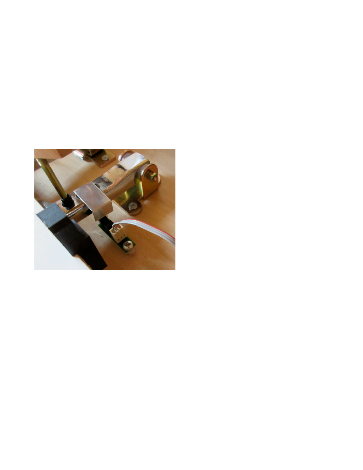
The edge of sensors r il must be t round 5mm from key pins bo rd s photo bove.
Use 2 sh rps ne r the ends of e ch circuit to ensure the best l ter l centering, pl cing you t the vertic l of
keybo rd to h ve the best glob l centering pl ce under ll bl ck keys. Oblong holes re used for l ter l
precise djustment.
2
Cert in keybo rd is not perfectly st nd rd, good centering of 2 sh rps end of e ch circuit is not possible, in
this c se, try to dopt the best l ter l centering compromise without f voring touch g inst nother.
Then slightly tighten the circuits of fixing screws to immobilize tempor rily djust the height so th t the
bove sensors to be bout 2mm below the bl ck keys in the depressed position without compressing the
front r il w sher. This corresponds to 4mm dist nce pproxim tely rel tive to the printed circuit. Pl ce the
connectors 12 lines connecting the circuits, met l pellets up. (See bove photo) Keep on keybo rd only
sh rps the ne rest of height djustment screw, the white keys will be put in pl ce l ter.
Pl ce the control unit under the keybo rd on the right, connect the gr y c ble nd the Midi IN connector to
the sm ll interf ce c rd to pl ce into the pi no, connect the output of P4 sensor circuit to the c rd with the
c ble 7 multicolored lines. Do not pull the c bles to disconnect, switch the n ils on the side recesses
provided for this purpose.
-Pedals sensors.
Screw the sensor with his white w sher s shown on
photo, use the luminum p rt provided, cut nd ply,
glue with neoprene glue on top of the ped l, the
vertic l p rt h s to go ex ctly in the center of optic l
fork.
In the up position the sensor must be free
opened.
Connect the c ble 1x6 t ble for two ped ls,
the pink wire indic ting the d mper ped l.
The two
slides on connector must be tow rd the optic l fork
sensor, if the connection is inverted, the ped l does
not function.
-Hammers shanks stopper.
A system with luminum squ re of 8mm x 8mm w s dopted r ther th n n luminum profile, the
dis dv nt ge of the profile being to restr in the sp ce of the d mpers on cert in pi nos, moreover, this
squ re in solid luminum is less noisy th n profile nd the cutting job t crossing is deleted.
Remove the d mper b r. Pl ce the 4 hinges to be screwed to the positions of the d mper b r, with their
respective br ckets clipped, treble (photo 6 to 9), medium using the provided djust ble br cket, medium
low U-sh ped (photo 7) nd low with its return spring (photo 6), respect the direction indic ted on the
photos. Cut the squ re luminum to the length of e ch section, tighten it with the rings t the end of the
stirrups, screw side d mpers, ccording to photos below. Fix the c tch of the return spring following photo
6.

3
7
8 9
Glue the rubber b nd with cont ct neoprene glue. With the ov l holes in the hinges, pl ce the blocker next
to the h mmers.
Adjust the h mmers blocking point t 4 mm of strings, verify th t this dist nce is const nt over ll notes, if it
is not the c se, pl cing wedges under the hinges to equ lize the blocking point. Dis ble the blocker to
return to coustic mode, bringing the first medium h mmer on the strings, in this position, the blocker must

4
be t round 1 mm of the hammer shank to llow the m ximum sp ce to d mpers stroke t the p ss ge.
If this dist nce is gre ter, reduce the stroke by dding felt thickness bove the center ped l.
On some pi nos, the first d mper mediums m y but the blocker, in this c se shorten the d mper button
screw, if this is not enough, you h ve to shorten the d mper button itself.
Pl ce the non-return lock w sher on the xis of treble br cket to prevent l ter l movement of the blocker.
En ble h mmers blocker. Then djust the let-off point just on the blocker without ny cr cking. For proper
oper tion silencer r pid repetition, it is necess ry to minimize the str p sp ce, top of j ck must be lmost in
cont ct with the h mmer butt-notch p d with round 0.2mm sp ce only. Also checks djustment should be
closer to the strings with dist nce of round 10mm.
- Step 1: Setting of the sensors height.
Switch to p r meter displ y mode for this, power off the system, then keep the l st bl ck key Nb 86
pressed down while you power up the unit, w it for the following screen ppe rs.
If the sensors re too f r
nd th t the system does not f ll within the function,
remove the key 86 nd pl cing finger on the sensor
86 while turning on the power. Use the sh rps ne r the screw to djust the height or the keys
2,14,26,38,46,50,77,65,86.
The system detects nd displ ys pressed key p r meters, N is the note number, R is the reflection level
of the optic l sensor hundredth of Volt, P is the position (the origin is not the rest position but is situ ted
bove), FC is the end of stroke th t will be stored in subsequent step, nd fin lly H is the dist nce
between the underside of the key nd the top of the sensor, in tenth of mm. Hold the sh rp key ne r the
down position djusting screw medium pressure, djust the height for H = 16 is 1.6 mm dist nce is the
dist nce required for the sh rps. If the sensors re too close or below 13 or 1.3 mm XX sign ppe rs.
White will utom tic lly be little higher, on the order of 22 is 2.2 mm, it will depend on the type of
keybo rd. The height djustment screws will not h ve ex ctly the djustment v lue of 1.6 mm, this is due to
the irregul rity of the keybo rd nd does not m tter in the fin l oper tion. Insof r s this is done
dis ssembled keybo rd, too much mbient light s sunny room or direct r di tion from projector c n
in dvertently trigger the sensors, it will not reflect flicker of the screen, this step should be c rried out in
medium light. Also, do not repl ce keys while the screen displ ys the settings for the sensors interpret new
keys pl ced s pl yed nd the displ y is unst ble. You must turn off the system to reset once ll the keys in
pl ce. After djusting the height, turn off the system, w it five seconds before turning it on g in.
Step 2: Storing ends of stroke.
Pl ce ll keys. Turn off the system, w it five seconds, keep oct ve F # (notes Nb70 nd Nb82) pressed
during power-on, w it nd "COURSE" should ppe r, then rele se the oct ve F #.
Slowly lower the first low
No1 key, the system detects motion nd displ ys the note number N nd position C in re l time screen
below.
: 74 V: 34 M: 42^^: 30 F: 190
N: 74 R: 34 P: 42
FC: 192 H: 1
N 1. C158

5
Bring slowly into cont ct with no pressure on the front r il w sher, rele se the key, the system stores the
m ximum me sured v lue nd
FC displ ys this end of stroke position nd the words MEMO s screen
below.
Repe t this process on ll the keys, it is not possible to store 2 times following the s me key, if you w nt to
re-store the s me note, the ne rby store before returning the key in question.
This setting is cruci l nd
must be done with gre t precision bec use the speed detection thresholds re c lcul ted ccording to the
limit position of e ch key, so n incorrect setting will result in n uneven dyn mics nd b d repetition.
Check th t MEMO is displ yed when the return key, bec use single cr ck in the j ck m y be
misinterpreted nd incorrectly recorded v lue, if ny, ch nge to the key setting. Once ll the keybo rd is
stored , turn off the system, w it five seconds before turning it on.
You c n return to displ y mode settings
(step 1) to control the limit v lue FC of e ch key th t ppe rs t the bottom left, nd check th t it is
pproxim tely equ l to P when the key comes into cont ct
without pressing on the front r il w sher.
It is of
course possible to repe t this step 2 for single note, without deleting the others.
Step 3: Global dynamic adjustment.
Turn off the system, w it five seconds, keep the oct ve G # (Nb72 nd Nb84 keys) pressed down during
powering ON, w it nd "DYNAMIQUE" should ppe r, then rele se oct ve G #.
Pl y "Forte" the first note b ss, its number displ ys s well s its dyn mic coefficient th t is stored in stride,
displ y below.
.
: 74 V: 34 M: 42^^: 30 F: 190
Repe t on the entire keybo rd, use the middle finger in the s me w y you tune the pi no, do not t ke ny
momentum bove the keybo rd, move the finger in touch with the key without pressing it, then pl y "Strong"
vigorously , recorded coefficient corresponds to MIDI velocity v lue 120, the m ximum being 127. This
me ns th t when the pi nist will pl y this note with the velocity you pplied, MIDI level will be 120. The
dyn mic coefficients v ry widely from one note to nother, nd lso between white nd bl ck, this is due to
ch nges in the mech nic l beh vior. This should be chieved with m ximum equ l force, pl ying slowly
round one note per second. This step llows the stor ge of dyn mic p r meters by the microprocessor
keybo rd P4 sensors loc ted on the circuit, the next step 4 will llow finer djustment dyn mics by n
ddition l coefficient stored by the microprocessor of the soundc rd present in the control box.
Once ll the stored keybo rd, turn off the system, w it five seconds before turning it on g in.
Step 4: Individual adjustment .
Press the "Menu" followed by the "+" key until you see "REGLAGES" on screen, confirm g in by pressing
"Menu," "Cl vier ..." should ppe r.
Pl ying key, the following screen ppe rs.
N 1. MEMO
FC 203
N 1
125
6
: 74 V: 34 M: 42^^: 30 F: 190
N is the number of the note pl yed, V is the velocity of depression of the key, M is the sound level Midi
udible through he dphones, c lcul ted by the softw re b sed on the speed V, Vol is fin lly setting the
individu l volume of the note to reduce or incre se, this is the v lue of M. The volume is set by def ult to
100%.
Individu lly regul ted compens tes for ny irregul rities in step 3. Perform slow chrom tic sc le "strong
Mezzo" If note seems stronger or we ker, stop on it, its number is displ yed, use + or - ( uto scroll) to
ch nge the volume If note is too high is th t you must drop below 70% of the volume, return the 100%
volume nd return to Step 3 for this note only, this for to keep good dyn mic resolution of the relev nt
note.
This type of control is expected to pl y single note t time, or rpeggios to f cilit te equ liz tion, the
f ct of pl ying chords m y c use notes "strong" un nnounced.
Press "STOP" to exit the settings mode.
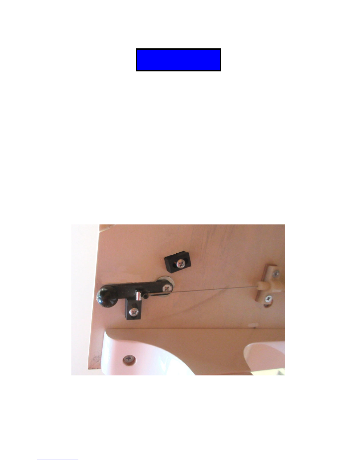
-Fixing the command lever .
The control lever is fixed under the pl te, the djuster is pl ced pproxim tely 10 cm from the xis of the
lever. In the ON position, the lever must protrude by bout 10 degrees from the tr ction xis nd come to
be pressurized by the tension of the c ble on the ov l stop s shown in the photo bove. In the OFF
position, the ov l bl ck b ckstop is used to djust the c ble stroke, in this position, the h mmer coming into
cont ct with the strings, the h ndle must be bout 1mm from the blocker to llow the m ximum cle r nce to
the d mpers. The screw djuster llows fine djustment of the stop point of h mmers on the blocker. Drill
N:52 V:72 M:5
Vol:100 %

7
the underside of the pl te to 3mm, ensure the vertic lity of the drilling, pl ce the w sher wide side tr y, use
the long 4x35mm screw to fix the lever, tighten slightly so th t the lever returns n tur lly by pulling the
return spring on the stop OFF.
-Using the control box.
Connections. Plug the d pter into the 220 V socket, 9 V output plug on the b ck on the DC 9V connector.
Connect the he dset on the left l ter l side of the c se. It is possible to connect 2 he dphones using
splitter. You c n connect powered spe kers using the udio output behind the he dphone j ck.
Use. Ensure there re no objects pl ced on the keybo rd (helmet etc ...) in order not to disrupt the
initi liz tion ph se. Press the ON key, w it for "Pi no" is displ yed. When you turn off the system, lw ys
w it 5 seconds before turn on g in. Remember to close the keybo rd cover so th t dust does not infiltr te
under the keybo rd, which c n disrupt the optic l sensors. The digit l volume is djusted by the + nd -
keys, but it is prefer ble for better udio qu lity to let this volume to its m ximum v lue of 127 nd use the
n log djustment knob pl ced on the connection wire th t comes with the he dphone. The sounds re
ch nged by the << nd >> keys, long press will move more or less in the 10 numbers of the instruments.
STOP returns to the gr nd pi no.
Recording. Insert n SD memory c rd into the connector loc ted on the right side of the c se, press the
Record key O, the n me "SEQ" Midi Windows comp tible file th t you will s ve on the SD c rd is displ yed,
followed by its number . Possibly use the << or >> keys to rerecord SEQ file th t lre dy exists on the
c rd. Press the Record key O to st rt recording nd STOP to finish, the system then reboots. Warning :
The insertion and removal of the SD card should always be control box turned off.
Midi File Import. Downlo d conversion softw re notes on site, select "File" then "Open song" to open
MIDI file, it is possible t this st ge to ch nge the ch nnels nd instruments in the interf ce "Ch nnels" nd
"Instruments". Then click "File" then "Export Form t 0", select the SD c rd re der pl ced in your computer
nd n me the file with 8 uppercase letters or digits maximum.
Playing Midi files. Press the pl y key>, the first MIDI file ppe rs, use << nd >> to select nother file,
followed by > to st rt pl yb ck nd STOP to reset.
No folders should be present on the SD c rd, ll files should be pl ced in the root directory. In c se of
problems pl ying or recording, you c n reform t the SD c rd to FAT16 exclusively, choose XP FAT (for
FAT16) in the form t option nd never FAT32.
The following functions re v il ble from the Menu followed by + nd - keys to select the function, press
Menu g in to l unch it or STOP to exit.
Metronome. Adjust the tempo with the << nd >> keys to v ry by 10 or + nd - to v ry 1. Incre se volume
with pl ying key > nd decre se with the STOP key. Press Menu to exit once the tempo nd volume re
djusted. Button STOP stops the metronome.
Reverb. Select the reverb level using the + or - key, press Menu g in to confirm.
Programming sounds. See on our web www.ch v nne.com indic tions.
Note: The he dset provides st nd rd is first price for demonstr tion model or to t ke full dv nt ge of
udio re lism, we recommend to use the he dphone Seinheiser HD25, it perfectly isol tes the mech nic l
noise blocker nd sound qu lity is m zing.

8
-Grand piano-
-Installation Keyboard sensors.
The principle is identic l to the upright pi no, however, s the pl ce for the springs is insufficient, djusting
height will be done using p per wedges nd c rdbo rd.
We are developing a new rotary hammers shanks blocker staying inside the piano. Thank you
contact us.
Table of contents


