Checkpoint FXS Series User manual

Series FXS Solar Injection System
Operating Manual
Page 1 of 35
CheckPoint Headquarters
CheckPoint UK
CheckPoint Systems Pte Ltd
21356 Marion Lane
C2/C3 Lombard Centre
21 Toh Guan Road East
Mandeville, Louisiana 70471
Kirkhill Place, Kirkhill Industrial Estate
#04-17 Toh Guan Centre
United States of America
Dyce, Aberdeen AB21 0GU Scotland
Singapore 608 609
+1 (504) 340-0770
+44 (0)1224 775205
+65 6261 7687
Series FXS
Solar Injection System
Operating Manual
CP/MAN-PRD-008 REV. 02 EFF. DATE: 07/06/2022
CP Pumps & Systems FZE
Unit AA08, LIU 10
Jebel Ali South | PO Box 262131
Dubai | UAE
+971 (4) 8806278

Series FXS Solar Injection System
Operating Manual
Page 2 of 35
TABLE OF CONTENTS
PUMP INSTALLATION 5
1.1 Process Design & Setup ...........................................................................................................................5
1.2 Connecting the Chemical Supply...........................................................................................................8
1.3 Connecting the Solar Power Supply ....................................................................................................10
2. PUMP OPERATION 11
2.1 Bleeding/Priming the Injector Head ...................................................................................................11
2.2 Setting and Adjusting the Pump Delivery Volume ...........................................................................12
2.3 Setting the Pump Stroke Rate..............................................................................................................13
2.4 Packing Adjustment............................................................................................................................... 17
2.5 Packing Replacement ............................................................................................................................18
3. PUMP MAINTENANCE 20
3.1 Lubrication .............................................................................................................................................. 20
4. FUSES 21
4.1 General Information.................................................................................................................................21
5. SOLAR SUPPORT COMPONENTS 22
5.1 Battery Bank ........................................................................................................................................... 22
5.2 Charge Controller ................................................................................................................................... 23
6. FLOW INFORMATION 31
6.1 Flow Charts..............................................................................................................................................31
CP/MAN-PRD-008 REV. 02 EFF. DATE: 07/06/2022

Series FXS Solar Injection System
Operating Manual
Page 3 of 35
7. TROUBLESHOOTING 32
7.1 Pump Runs, but Chemical does not Discharge at the Correct Rate ..............................................32
7.2 Pump Does Not Stroke .......................................................................................................................... 33
7.3 Pump is Excessively Noisy ....................................................................................................................33
7.4 Chemical Leakage from Packing..........................................................................................................33
7.5 Other Problems ......................................................................................................................................34
APPENDIX 35
CP/MAN-PRD-008 REV. 02 EFF. DATE: 07/06/2022

Series FXS Solar Injection System
Operating Manual
Page 4 of 35
CheckPoint’s Solar FXS Chemical Injection System was designed to provide a quality, low-maintenance,
and environmentally friendly chemical injection solution. From its high-grade materials of construction
(316 SS, Hastelloy, and PVC) to its unique tripod stand, this system was designed with maximum utility in
mind.
The Series FXS Solar Injection System’s lightweight, portable, and sturdy design lends itself to easy
mobility in the field. Each system is prewired with industry-standard MC4 quick connectors for both the
panel and the pump, ensuring minimal installation and setup time. The entire system was designed to be
effortlessly assembled by one person in as little as fifteen minutes. The front access enclosure containing
its battery and charge controller is raised to an easy-access level that provides clearance for rain or snow.
The integrated base allows the pump to dependably stand alone or to be easily bolted to a structure.
To ensure proper operation and to maximize the system’s durability, please read and follow this manual.
Failure to correctly install and maintain the product is the primary cause of premature failure and voids
the product warranty.
NOTE: This IOM applies to the CheckPoint Solar FXS Chemical Injection Pumps, part number FXS2-
(FXS Code)-(Injection Assembly) for Series 1250 head, and FXS5-(FXS Code)-(Injection
Assembly) for Series 1500 head.
NOTE: Important illustrations, graphs, and charts are located throughout this manual.
CP/MAN-PRD-008 REV. 02 EFF. DATE: 07/06/2022

Series FXS Solar Injection System
Operating Manual
Page 5 of 35
PUMP INSTALLATION
1.1 Process Design & Setup
1.1.1 Before installation, please inspect the pump carefully for any possible in-transit damage. If the
pump appears to be damaged, immediately call your authorized CheckPoint distributor, or call CheckPoint
customer service directly at (800) 847-7867 or (504) 340-0770 to confirm damaged condition. If CheckPoint
determines that the damage has occurred during transit, you will need to file a claim with the carrier.
FIGURE 1: TYPICAL INSTALLATION SCHEMATIC
CheckPoint packages are available for FXS Series pumps that contain all necessary components indicated within the PACKAGE LIMIT in Figure 1.
CheckPoint can supply packages that contain ALL components in Figure 1, including the tank, mounted on a single skid with or without full leak
containment.
1. Suction line block valve 4. Calibration Gauge Block Valve 7. Discharge line block valve 10. Discharge Pressure Gauge
2. CP Chemical Filter* 5. CP Calibration Gauge* 8. Pressure Relief Valve 11. Discharge Check Valve
3. Pulsation Dampener 6. Tank Gauge 9. CP DC FXS Chemical Pump
All items in Figure 1 can be purchased directly from CheckPoint.
Call today for our latest prices on pumps, gauges, packages and other components.
*CheckPoint original equipment manufacturer (OEM) products
CP/MAN-PRD-008 REV. 02 EFF. DATE: 07/06/2022

Series FXS Solar Injection System
Operating Manual
Page 6 of 35
1.1.2 Referring to Figure 1, ensure that all necessary components are present in your injection system
and are in good working order. CheckPoint recommends all components shown above to maximize
productivity and life of the pump in typical field or plant use. CheckPoint is available to answer all of your
process questions or to help design and build a package system utilizing components appropriate for your
application.
NOTE: In Figure 1, the secondary chemical filter is optional under certain conditions but is highly
recommended.
1.1.3 CheckPoint requires horizontal mounting of Solar FXS model pumps. Failure to do so will result in
oil leakage from the breather vent. The Solar FXS comes standard with a floor stand to ensure proper
orientation.
1.1.4 Accurately setting the flow rate of the pump can only be accomplished with either a suction-side
calibration gauge or a discharge flow meter. Many variables, including temperature, chemical viscosity, and
other environmental factors, preclude the use of tables, graphs, or formulas to determine the rate of
injection. Additionally, without a calibration gauge or flow meter, it cannot be determined if the pump is
primed and functioning normally. For instructions on the proper use of a suction-side calibration gauge,
please refer to Section 2.3.1, Setting Pump Speed Using a Calibration Gauge for more information. The
proper placement of a calibration gauge is shown in Figure 1, item 5. CheckPoint offers a complete range
of accurate and durable calibration gauges and discharge-side flow meters suitable for Solar FXS pump
service.
NOTE: It is necessary to attach a vent tube to the top of all calibration gauges, chemical tanks, and
tank level gauges. The height of the top of each vent tube should always be greater than the
highest possible liquid level in the system, and the tube should have features to prevent water
entry, such as a 180 degree bend.
1.1.5 The Solar FXS does not require flooded suction or positive chemical pressure to prime and can
therefore be mounted above the chemical container. This feature depends upon proper adherence to all
points made in Section 1.1.6. Solar FXS pumps with plunger sizes of 1/8” and 3/16”, and applications where
the injection chemical is prone to gas off, will benefit by having flooded suctions.
1.1.6 ALL COMPONENTS AND PIPEWORK BETWEEN THE CHEMICAL TANK AND THE SUCTION CHECK
VALVE OF THE PUMP MUST BE 100% BUBBLE-TIGHT AND FULLY COMPATIBLE WITH THE CHEMICAL AND
WITH EACH OTHER. FAILURE TO ADHERE STRICTLY TO THIS DIRECTIVE WILL LEAD TO LOSS OF PRIME AND
DAMAGE TO THE WETTED SEALS AND PLUNGER. SPECIFICALLY:
1.1.6.1 Any fitting or screw-on joint without Teflon™ tape or other acceptable sealant may allow air at
atmospheric pressure to enter the suction tubing, even if no chemical leakage is visible.
1.1.6.2 Dissimilar metals in the suction side of the injection system may react with each other, creating gas
bubbles that will be carried into the pump head. All suction components, tubing, pipe, fittings, and valves
must be composed of similar or compatible materials. Please note that CheckPoint offers wetted parts
comprised of 316 SS, Hastelloy C, PVC, Titanium and Alloy 20.
CP/MAN-PRD-008 REV. 02 EFF. DATE: 07/06/2022

Series FXS Solar Injection System
Operating Manual
Page 7 of 35
1.1.7 CheckPoint ships the FXS pump with a pre-drilled floor stand, and this is the recommended method
for mounting the pump. The pump may be mounted to a skid or other surface in a number of ways;
however, clamping around the outside of the pump can permanently affect the cylindricity of the injection
head or housing, which will void the product warranty. Furthermore, this method reduces accessibility
during maintenance and troubleshooting and is therefore not recommended.
1.1.8 Always check to ensure that all process block valves (labeled as items 1 & 7 in Figure 1) are closed
prior to disconnecting or reinstalling any chemical injection pump. There should always be a block valve
placed between a properly installed pump and the process flow and the chemical supply. Conversely, while
the pump is in operation, the suction and discharge block valves should always remain open. The
calibration gauge ball valve (labeled as item 4 in Figure 1) should remain closed at all times unless flow rate
calibration is being performed. Failure to close the calibration gauge ball valve may allow air to enter the
injection head, which may subsequently cause loss of prime.
1.1.9 The pump suction line should be sized appropriately to the flow rate to avoid cavitation. A general
rule of thumb is to size the suction line such that the instantaneous flow velocity through the line does not
exceed 2 feet per second at any point. For multiple pump installations, for extremely viscous chemicals,
and for chemicals with low vapor pressures, additional allowances may be needed. Contact CheckPoint or
your authorized CheckPoint distributor for design assistance.
1.1.10 TO AVOID OVER-PRESSURIZING CHEMICAL DISCHARGE LINES, CHECKPOINT REQUIRES PLACING A
PROPERLY TESTED AND CALIBRATED PRESSURE RELIEF VALVE (PRV labeled as item 8 in figure 1) BETWEEN
THE DISCHARGE PORT OF THE PUMP AND THE PROCESS FLOW. THE PRV DISCHARGE CAN BE RUN TO A
TEE UPSTREAM OF THE PUMP’S CHEMICAL SUCTION CHECK VALVE OR REROUTED TO TANK. FAILURE TO
USE A PRV IS INHERENTLY UNSAFE AND MAY LEAD TO CATASTROPHIC FAILURE OF PROCESS EQUIPMENT
DUE TO EXCESSIVE PRESSURE. CHECKPOINT IS NOT RESPONSIBLE FOR ANY DAMAGE CAUSED BY OVER-
PRESSURIZED CHEMICAL. CheckPoint offers a range of PRVs suitable for use with the FXS pump.
CAUTION: When using a pressure relief valve (PRV), the chemical tank MUST BE properly vented
to atmosphere to avoid the possibility of over-pressurizing the tank if the pressure
relief valve actuates.
1.1.11 Although the FXS does not require the use of a pulsation dampener for proper operation, pulsation
dampeners may be required in your installation depending on a variety of factors. Consult with CheckPoint
if you have any concerns about pulsation.
CP/MAN-PRD-008 REV. 02 EFF. DATE: 07/06/2022

Series FXS Solar Injection System
Operating Manual
Page 8 of 35
1.2 Connecting the Chemical Supply
1.2.1 Clean all suction lines and check chemical containers to ensure that they are free of all foreign
matter, sand, sludge, or chemical buildup.
NOTE: Removing foreign debris from suction lines and chemical containers will substantially extend
the life of the packing and other components of the pump. Even a new chemical tank can
contain debris that can be carried into the pump and cause damage.
NOTE: If early packing failure is observed during operation, a common cause is the presence of
abrasive particles carried into the pump through the suction plumbing. Use of a pre-suction
in-line chemical filter is highly recommended. CheckPoint offers a range of chemical filters
suitable for use with the FXS solar pump.
CAUTION: Substantial scoring of the plunger can lead to severe leakage of chemical into the
surrounding environment.
1.2.2 Connect the chemical suction line to the suction check valve on the pump head (See illustrations in
CheckPoint’s Series FXS Solar Injection System Parts List document, available upon request or for download
at cppumps.com). The suction check valve is a 1/4"MNPT for the Series 1250 and 1/2" MNPT for the Series
1500. Care must be taken not to over-tighten NPT connections. For more information regarding the
procedure for properly making NPT connections, please refer to the CheckPoint NPT connection
procedure, available on request.
NOTE: Always apply Teflon™ tape or other appropriate thread sealant to the check valve threads
prior to attachment to prevent leakage. Take care not to allow Teflon™ tape or other
appropriate thread sealant to cover check valve ports or become frayed to the point that
pieces of the tape may become lodged in check valves, causing loss of prime.
NOTE: Never relocate the suction check valve away from the chemical head. To operate properly,
the check valve must remain directly attached to the chemical head.
1.2.3 Connect the discharge line to the pump discharge check valve. (See illustrations in CheckPoint’s
Series FXS Solar Injection System Parts List document, available upon request or for download at
cppumps.com). The discharge port is 1/4" FNPT for the Series 1250 and 1/2" FNPT for the Series 1500. Care
must be taken not to over-tighten NPT connections. For more information regarding the procedure for
properly making NPT connections, please refer to the CheckPoint NPT connection procedure, available on
request.
1.2.4 Open the process block valve (item 7 in Figure 1), to allow the process pressure to reach the chemical
head. Correct any leakage observed.
CP/MAN-PRD-008 REV. 02 EFF. DATE: 07/06/2022

Series FXS Solar Injection System
Operating Manual
Page 9 of 35
CAUTION: The Solar FXS Series 1250 pump universal chemical head is rated for a maximum
working pressure of 7,500 PSIG, and the 1250 1/8” head is rated for 12,000 PSIG. The
FXS Series 1500 pump universal chemical head is rated for a maximum working
pressure of 7,500 PSIG, and the 1500 HP head is rated for 15,000 PSIG. If the discharge
line is inadvertently blocked for any reason, the pump can generate pressures in
excess of the indicated rated pressures. A relief valve MUST be placed between the
discharge port and the process flow to prevent this condition.
NOTE: Always open the process block valve prior to operating the pump. Operating the pump with
a closed block valve can generate enough pressure to rupture the discharge line, damage
process equipment and the chemical head itself, and reduce the overall life of the pump.
CAUTION: Discharge line size must remain consistant to avoid unnecessary backpressure to the
pump. Installing devices with small orifices may cause the pump to consume excess
power, reduce the life of the battery bank, and cause the pump to stop. All ball valves,
check valves, flow meters, and other equipment and accessories must be
appropriately sized with the discharge line. For plunger sizes of 1/8”, 3/16”, 3/8” and
1/2”, the discharge line size should be 3/8” or greater; for plunger sizes of 3/4”, 1” and
1-1/2” discharge line size should be 1/2” or greater.
CP/MAN-PRD-008 REV. 02 EFF. DATE: 07/06/2022
Series FXS Solar Injection System
Operating Manual
Page 10 of 35
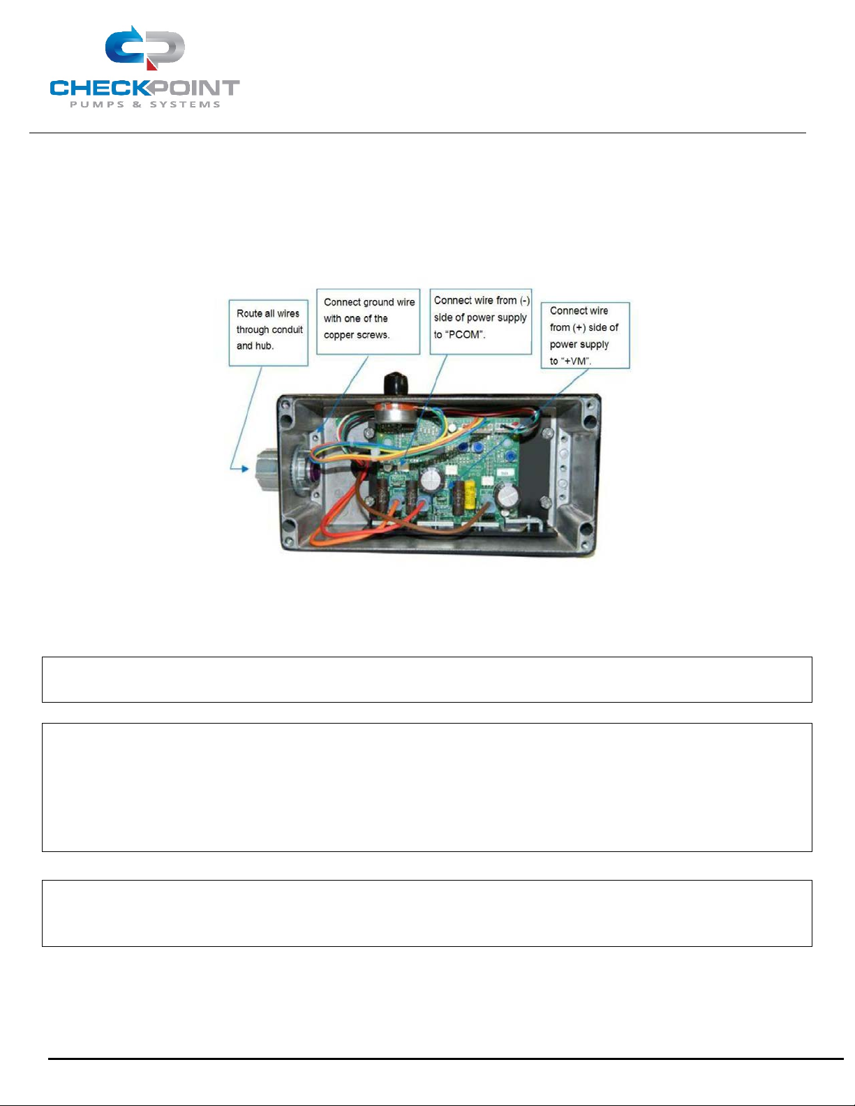
1.3 Connecting the Solar Power Supply
FIGURE 2: ELECTRICAL INSTALLATION LOCATION
1.3.1 The solar powered electric motor must be connected in accordance with all local regulations,
including overload protection. FXS Solar pumps are equipped with Class 1, Div 2 (Group A, B, C, D) 1/5 HP
motors.
CAUTION: INCORRECTLY CONNECTING POWER SUPPLY TO THE MOTOR WILL RESULT IN DAMAGE
TO THE MOTOR CONTROL BOARD AND WILL VOID THE PUMP WARRANTY.
CAUTION: NEVER TAMPER WITH THE SETTINGS OF THE PCB MOUNTED POTENTIOMETERS. THESE
CONTROLS ARE SPECIFICALLY INTENDED FOR FACTORY CALIBRATION PURPOSES ONLY,
AND ALLOW FOR SLIGHT CORRECTIONS TO COMPONENT RESISTANCE VARIATIONS.
TAMPERING WITH THESE CONTROLS MAY RESULT IN REDUCED FLOW RATES,
MOTOR/PUMP STALLING UNDER LOWER DISCHARGE PRESSURES, OR INCREASED POWER
CONSUMPTION RESULTING IN BATTERY FAILURE AND WILL VOID PRODUCT WARRANTY.
NOTE: It is important that the solar panels are positioned correctly and are in a space that would
avoid shading from direct sunlight to allow for maximum sunlight hours at the installation
location. Please refer to local standards for appropriate angle and direction of solar panels.
1.3.2 The complete installation should be equipped with an on/off switch (Figure 12A) that is easily and
quickly accessible by the user. Solar power packs are equipped with charge controllers which have on/off
capabilities or will have a main breaker in instances where more than one charge controller is necessary.
CP/MAN-PRD-008 REV. 02 EFF. DATE: 07/06/2022

Series FXS Solar Injection System
Operating Manual
Page 11 of 35
2. PUMP OPERATION
2.1 Bleeding/Priming the Injector Head
NOTE: Prior to initial pump operation, ensure the suction check valve is connected to adequate
chemical supply per Section 1.2.
2.1.1 The bleed screw on the Series 1500 injection head is fitted with a 1/8" FNPT connector to allow the
user to tube chemical used in the bleeding process to the proper containment area or vessel. An optional
threaded bleed screw is also available for the Series 1250 injection heads as well.
2.1.2 Prior to bleeding air from the pump head, check to ensure that the packing nut is properly adjusted.
Before attempting to adjust or tighten the packing nut, refer to Section 2.4, Packing Adjustment. It is
important not to overtighten the packing nut.
2.1.3 Open the chemical supply block valve.
2.1.4 Open the process block valve.
CAUTION: OTHER THAN DURING BRIEF TESTING, NEVER OPERATE THE PUMP WITHOUT CHEMICAL
SUPPLY AVAILABLE AND FLOWING FREELY. DOING SO WILL DECREASE THE LIFE OF THE
PACKING, HASTEN CHEMICAL LEAKAGE, AND VOID THE PUMP WARRANTY.
2.1.5 Start the pump via on/off button located on the solar charge controller.
2.1.6 Open the bleed screw 1-1/2 to 2 turns. The pump will begin to pull air and chemical through the
chemical supply plumbing, into the head, and out of the bleed valve port. Leave the valve open until a solid
stream of chemical pumps out of the bleed port with each stroke of the pump.
NOTE: If the pump is not new, it is possible for dried or solidified chemical to be present in the
bleed assembly. If your pump does not bleed when following the directions above, try
cleaning these items in solvent or replacing them, and then repeat the above process.
2.1.7 Close the bleed screw until the chemical flow through the bleed port stops.
CAUTION: DO NOT OVER-TIGHTEN THE BLEED SCREW. TIGHTEN THE BLEED SCREW ONLY UNTIL
CHEMICAL STOPS FLOWING AND UNTIL SNUG WITH 7/16” WRENCH FOR SERIES 1250
INJECTION HEADS AND 7/8” FOR SERIES 1500 INJECTION HEADS. TORQUE VALUE IS
APPROXIMATELY 10 IN-LBS FOR SERIES 1250 INJECTION HEADS AND 15 IN-LBS FOR
SERIES 1500 INJECTION HEADS. APPLYING EXCESS TORQUE TO THE BLEED VALVE MAY
IMPAIR FUTURE VALVE OPERATION.
NOTE: Occasionally, soon after closing the bleed assembly, you may observe packing leakage. If so,
this is usually due to a loose packing nut. Stop pump stroking, relieve pressure from inside
the head, and adjust the packing nut per the instructions in Section 2.4: Packing Adjustment.
2.1.8 Solar FXS motors are equipped with an integrated manual motor speed control located on the side
of the motor, and can be supplied with the ability to accept a 0–5v signal for remote adjustment. Adjust
the delivery volume per directions in Section 2.2: below.
CP/MAN-PRD-008 REV. 02 EFF. DATE: 07/06/2022
Series FXS Solar Injection System
Operating Manual
Page 12 of 35
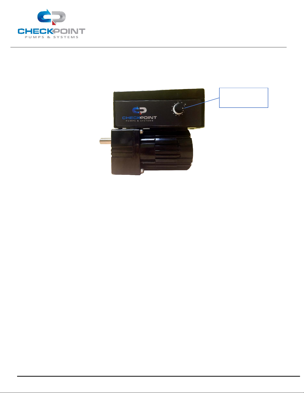
2.2 Setting and Adjusting the Pump Delivery Volume
FIGURE 3: SPEED POTENTIOMETER LOCATION
2.2.1 The stroke length of the FXS Series pump remains constant at all times.
2.2.2 The pump delivery volume is controlled by varying the RPMs of the power drive mechanism; the
integrated speed control is located on the front side of the motor as shown above in Figure 3.
2.2.3 Adjusting the RPM during operation will not damage the FXS Series pump or motor.
2.2.4 The speed should only be set from 10 to 100%.
Speed
Potentiometer
CP/MAN-PRD-008 REV. 02 EFF. DATE: 07/06/2022

Series FXS Solar Injection System
Operating Manual
Page 13 of 35
2.3 Setting the Pump Stroke Rate
2.3.1 Setting Pump Speed Using a Calibration Gauge
NOTE: The Solar FXS Series pump maintains a constant stroke length during operation. The
discharge volume can only be varied through a change in RPM. This may be achieved with
either the manual motor speed control or with a remote 0-5 V signal. Rate calibration is
particularly important for solar pump systems since battery bank and solar array are
specifically sized based on application flow rate, discharge pressure, and installation location.
Failure to maintain flow rate supplied with application requirements may result in power loss
and battery failure. If application requirements have changed, please contact your
CheckPoint representitive to recalculate solar requirements.
The following directions are for setting the pump speed using a calibration gauge. A variety of calibration
gauges are available, including a complete line of CheckPoint gauges appropriately sized for every
CheckPoint pump. To ensure that your pump is working as it should and that chemical is being delivered
at the rate you need, it is important to use a calibration gauge or a discharge-side flow meter.
2.3.1.1 Most calibration gauges are designed to read properly when one full minute of pumping has taken
place. However, if the liquid level drops too fast to allow for a full minute, shorter periods are acceptable.
Try to size the gauge so that at least a 15 second test can be accomplished; however, a loss of accuracy
may result with test durations shorter than one minute. Alternatively, increasing the test duration will
increase accuracy.
2.3.1.2 Proper gauge placement and plumbing is important. Please refer to Figure 1 for appropriate valving
and placement, and for reference numbers as used in this section. The calibration gauge is labeled as item
5 in Figure 1.
2.3.1.3 With the pump either running or stopped, open the gauge fill valve (shown as item 4 in Figure 1).
The gauge should begin to fill. Continue filling until the chemical level is at or near the top markings on the
gauge, then close the gauge fill valve.
2.3.1.4 Ensure that the CheckPoint pump is running. Take note of the level of chemical in the gauge, using
the appropriate scale for your preferred pump output volume units. Usually, the gauge will show liters on
one scale and quarts or gallons on the other. It is best to write down the initial chemical level in order to
accurately calculate flow.
2.3.1.5 Open the gauge fill valve (Figure 1, item 4), and simultaneously close the chemical supply valve
(Figure 1, item 1). This isolates the pump and gauge so that the gauge is directly supplying the pump with
the chemical.
2.3.1.6 The level in the gauge should begin to fall (if it does not, or if the level seems to go down and then
back up with each stroke, refer to troubleshooting in Section 7). When the liquid level in the gauge nears
the bottom of the gauge, or when one minute has expired (whichever comes first), stop timing, note the
ending level on the gauge, and reopen the chemical supply valve.
CP/MAN-PRD-008 REV. 02 EFF. DATE: 07/06/2022
Series FXS Solar Injection System
Operating Manual
Page 14 of 35
2.3.1.7 Write down the amount of time in seconds and the final gauge reading, and close the gauge fill
valve.
NOTE: In cases where the chemical flow rate is extremely low, you may need to time for longer than
one minute to allow an adequate amount of chemical to move out of the gauge. Divide flow
rate by number of minutes timed to determine flow rate.
NOTE: Failure to reopen the chemical supply valve will result in the pump quickly depleting the
remaining chemical in the gauge and running on air, necessitating pump repriming.
2.3.1.8 The pumping volume (in the units specified on the gauge scale) can be determined by the following
equation:
PUMPING VOLUME =
[
END READING
]
- [BEGINNING READING]
DURATION OF READING IN SECONDS × 60
NOTE: To ensure accurate stroke rate measurement, allow sufficient measurement duration. Where
possible, allow at least thirty seconds of gauge drawdown. Generally, accuracy improves as
test duration increases.
2.3.2 Calculation of Stroke Rate
It is possible to calculate your pump’s required stroke rate. To do so, you must look up a volume factor,
multiply it by your desired chemical flow rate requirement, and compensate for the discharge pressure
using a graph. The instructions below will detail this process. This is most helpful when determining if a
particular plunger or pump size will output a required volume.
NOTE: This procedure should not be used as the sole method of setting the pump’s speed in the
field. It is not recommended for use with solar pumps other than as a quick reference tool to
visually ensure that the pump is running at the same speed, without having to manually check
flow rate with a calibration gauge or flow meter. Without checking pump output with a
calibration gauge, it cannot be positively determined that the pump is delivering the correct
liquid flow rate. For example, if the suction check valve is stuck due to debris or thickened
chemical, chemical would not be injected even if the stroke rate was properly set.
CP/MAN-PRD-008 REV. 02 EFF. DATE: 07/06/2022

Series FXS Solar Injection System
Operating Manual
Page 15 of 35
2.3.2.1 Using your desired chemical flow rate, calculate an Unrated Stroke Rate (USR). Figure 4 contains
volume factor using Series 1250. Figure 4A contains volume factor using Series 1500. Figure 5 contains
basic conversions to assist you. Figure 6 displays the volume de-rating percentage vs. discharge pressure.
UNRATED STROKE RATE (USR) (STROKES/MIN) = FLOW RATE (QT/DAY) × VOLUME FACTOR
FIGURE 4: VOLUME FACTOR TABLE, SERIES FXS 1250 TYPE
PLUNGER DIAMETER (IN)
VOLUME FACTOR
1/8”
3.477
1/4”
0.869
3/8”
0.386
1/2”
0.217
FIGURE 4A: VOLUME FACTOR TABLE, SERIES FXS 1500 TYPE
PLUNGER DIAMETER (IN)
VOLUME FACTOR
1/2”
1.049
3/4”
0.370
1”
0.227
FIGURE 5: GENERAL CONVERSION TABLE
TO CONVERT:
TO:
MULTIPLY BY:
GALLONS
QUARTS
4.00
LITERS
QUARTS
1.058
CUBIC INCHES
QUARTS
0.0173
MINUTES
DAYS
0.000694
CP/MAN-PRD-008 REV. 02 EFF. DATE: 07/06/2022

Series FXS Solar Injection System
Operating Manual
Page 16 of 35
FIGURE 6: VOLUME DE-RATING PERCENTAGE VS. DISCHARGE PRESSURE
2.3.2.2 Volume per stroke decreases as the discharge pressure rises. It is necessary to apply a Volume De-
Rating Percentage (VDP) to the Unrated Stroke Rate (USR). The VDP is based on the expected discharge
pressure the pump will experience. Use the VDP Graph (Figure 6) to find the VDP, taking care to use the
curve for your specific plunger diameter:
2.3.2.3 Use the resulting VDP to calculate the Target Stroke Rate as follows:
TARGET STROKE RATE = [USR]
[VDP] × 60
CP/MAN-PRD-008 REV. 02 EFF. DATE: 07/06/2022

Series FXS Solar Injection System
Operating Manual
Page 17 of 35
2.3.2.4 Finally, ensure that the Target Stroke Rate does not exceed the maximum recommended stroke
rate. If the Target Stroke Rate exceeds the maximum recommended stroke rate (per Figures 7 and 7A) for
the type of service you intend, it will be necessary to use a larger plunger size:
FIGURE 7: MAXIMUM RECOMMENDED STROKE RATE, SERIES 1250
TYPE OF SERVICE MAXIMUM RECOMMENDED
STROKE RATE
CONTINUOUS USE
67 STROKES PER MINUTE
FIGURE 7A: MAXIMUM STROKE RATE, SERIES 1500
TYPE OF SERVICE MAXIMUM RECOMMENDED
STROKE RATE
CONTINUOUS USE
67 STROKES PER MINUTE
2.3.2.5 Assuming your pump is correctly sized; simply adjust the integrated manual speed control or other
motor control device until the Target Stroke Rate is achieved.
2.4 Packing Adjustment
2.4.1 Packing adjustment is usually necessary when adjustable packing is installed in the pump and
leakage is observed around the packing nut or coming out of the weep hole drilled through the packing
nut. In most cases, if there is no leakage, no adjustment is necessary.
2.4.2 To adjust the packing, use a CheckPoint T55-101 packing adjuster, which is specifically designed for
this purpose. If one is not available, you may order one at no charge directly from CheckPoint. In an
emergency or if time is short, a 6" length of ¼" OD tubing or a metal rod may be used.
2.4.3 If the pump is already in service, the packing should generally be adjusted while the pump is
running.
2.4.4 To tighten the packing, insert the tool into one of the six shallow radial holes in the packing nut and
tighten the nut (away from the motor). Snug the nut until light pressure with one finger on the packing nut
tool no longer moves the packing nut.
2.4.5 From this point, TIGHTEN THE NUT 1/8 TURN ONLY as follows:
2.4.6 If adjusting the packing while pump is operating, pause after each 1/8 turn to determine if the
leakage has stopped, allowing for enough time to ensure that previous leakage has already drained from
the nut weep holes and threads. If the pump is still leaking, turn the packing nut an additional 1/8 turn and
check again. Continue turning the nut 1/8 turn at a time as many times as necessary to stop the leakage. If
the leakage cannot be stopped, or if excessive force is required to stop leakage, it is time to replace the
packing.
2.4.6.1 If adjusting the packing prior to new installation or when not currently running, tighten the nut 1/8
turn from the finger tight position.
CP/MAN-PRD-008 REV. 02 EFF. DATE: 07/06/2022

Series FXS Solar Injection System
Operating Manual
Page 18 of 35
NOTE: If the packing is being adjusted while the pump is running, the pump will typically not stall,
regardless of how much the packing nut is tightened. Therefore, care must be taken not to
apply too much pressure when adjusting the packing nut, as this can dramatically reduce
packing life and can overdraw power from the battery bank.
2.5 Packing Replacement
Follow the steps below to change the packing.
NOTE: Unless the pump has a dedicated high pressure head, the 3/16”, 1/4", and 3/8" plunger sizes
on the 1250 type head and the 1/2" plunger sizes on the 1500 type head require a metal
adapter sleeve in the packing gland. When removing the packing, this sleeve should also be
removed and cleaned. It is important to remember to reinstall the sleeve.
NOTE: The 3/16" plunger size on the Series 1250 and the 1/2" plunger sizes on the Series 1500
require an O-ring and a backup ring.
2.5.1 Shut off power to the pump.
2.5.2 Close the block valves on the chemical supply and discharge.
2.5.3 Disconnect the chemical supply from the pump at the suction check valve, and disconnect the
discharge line from the discharge check.
2.5.4 Remove the chemical head, by removing the two head bolts and then separating the head
component from the body of the pump.
2.5.5 Unscrew and remove the packing nut, using 1/4" tubing or a packing nut tool. A packing nut tool is
available at no charge from CheckPoint. For all sizes other than 3/16", proceed to step 2.5.7.
2.5.6 Using the access hole where the suction check valve was located, push out the packing and sleeve
with a punch or screwdriver. For the 3/8" Series 1250 head, proceed to step 2.5.10. For 1/2" Series 1250
head and the 1" Series 1500 head, proceed to step 2.5.11.
2.5.7 Remove the packing from the sleeve, along with the O-ring and backup ring on the small outside
diameter of the sleeve. Clean the sleeve and lightly grease it, then install the new O-ring and backup ring
supplied with your new packing. If you cannot locate these parts, please contact CheckPoint for
replacements. Your pump may leak chemical without replacing these components when you replace the
packing.
2.5.8 Replace the metal sleeve.
2.5.9 Examine the new set of packing closely and ensure, prior to installation, that it is oriented properly
according to Figure 8. Your packing will be similar to the cross sectional view shown.
CP/MAN-PRD-008 REV. 02 EFF. DATE: 07/06/2022

Series FXS Solar Injection System
Operating Manual
Page 19 of 35
FIGURE 8: TYPICAL PACKING INSTALLATION
NOTE: When replacing adjustable packing, always install the packing rings exactly as they are
shipped. Rearranging the order of the V-rings in an adjustable packing set will reduce the life
of the elastomer ring in the packing set.
2.5.10 Grease the packing rings on their outside diameters lightly and install them, one ring at a time. It is
important to adhere to the ring order and orientation as shown in the diagram.
NOTE: On the 1/8" and 3/16” Series 1250 head and 1/2” and 3/4" Series 1500 head, the packing fits
inside the sleeve, rather than directly into the packing gland.
2.5.11 On the 3/16” plunger model, replace the internal snap ring to retain the sleeve.
2.5.12 Grease the packing nut threads and replace the nut loosely by hand.
2.5.13 After inspection of the plunger for scars or ceramic damage, grease the plunger rod protruding from
the pump drive.
2.5.14 Taking care to insert the plunger into the packing without damaging or bending it, and replace the
chemical head onto the main body of the pump.
2.5.15 Grease the threads on the two head bolts, then insert and hand-tighten them.
2.5.16 Tighten the packing nut to the point where light pressure with one finger on the packing nut adjuster
will no longer move the packing nut.
2.5.17 Fully tighten down the head bolts. Failure to adhere to this procedure can lead to a misaligned head
and leaking packing.
2.5.18 Reattach all process lines to the chemical head, and open all isolation valves leading to the pump
chemical supply and discharge.
2.5.19 Adjust the packing nut per the directions in Section 2.4.
TOP RING – PEEK
FEMALE ADAPTER RING – TFM
BACKUP RING – TFM
ELASTOMER – (FFKM, VITON, BUNA)
MALE ADAPTER RING – TFM
CP/MAN-PRD-008 REV. 02 EFF. DATE: 07/06/2022

Series FXS Solar Injection System
Operating Manual
Page 20 of 35
3. PUMP MAINTENANCE
CheckPoint’s Solar FXS is designed to provide trouble-free operation for many years with little adjustment,
lubrication, or other routine maintenance. However, like any other device, proper maintenance can extend
the life of the product. This can include periodic cleaning of the chemical inlets and lubrication.
3.1 Lubrication
The CheckPoint Solar FXS drive contains internal rotating parts that require constant lubrication. The
housing for the drive acts as an oil reservoir and requires the oil level to be above the centerline of the
plunger adapter.
3.1.1 Startup The Solar FXS Series pumps are delivered without a filled reservoir. Prior to startup, fill the
FXS drive housing using 2 ounces (60mL) of SAE rated 5W-30 motor oil. CheckPoint recommends using
Mobil 1 Fully Synthetic 5W-30 for extended life. Before filling the housing with oil, ensure that the drain
plug in the bottom of the housing is installed. Remove the housing’s top breather vent, and using a suitable
funnel, pour 2 ounces (60mL) of oil into the housing. Replace the housing’s top breather vent using Teflon
tape on the threads. Care must be taken to avoid over-tightening NPT connections. For more information
regarding the procedure for properly making NPT connections, please refer to the CheckPoint NPT
connection procedure, available upon request.
3.1.2 Periodic Inspection Once a month, remove the top breather vent and inspect the fluid level to
ensure that the oil level is above the centerline of the pump. Add recommended oil as required to maintain
necessary lubrication levels for proper operation.
3.1.3 Oil Change CheckPoint recommends changing the drive oil every 2,000 hours using the previously
recommended oil (Mobil 1 Fully Synthetic 5W-30).
NOTE: CheckPoint offers an optional breather/oil level sight glass as a replacement for the supplied
top vent. As long as a supply of oil is maintained in the sight glass, sufficient oil for operation
is maintained.
CP/MAN-PRD-008 REV. 02 EFF. DATE: 07/06/2022
Table of contents


