Chelion iHome-INV Series User manual

i
Energy Storage System
iHome-INV Series
User Manual

Foreword
Energy Storage System iHome-INV Series
User Manual
ii
Foreword
Summaries
Thank you for choosing the energy storage system iHome-INV series (hereinafter referred to as
iHome-INV )!
This document gives a description of the energy storage system iHome-INV series, including the
features, performance, appearance, structure, working principles, installation, operation and
maintenance. etc.
Please save the manual after reading, in order to consult in the future.
The figures in this manual are just for reference, for details please see the actual product.
Suitable Model
Inverter
−iHome-INV3.6K-H1H01
−iHome-INV5K-H1H01
−iHome-INV6K-H1H01
The energy storage system iHome-INV series consists of inverter and battery.
Symbol Conventions
The manual quotes the safety symbols, these symbols used to prompt users to comply with safety
matters during installation, operation and maintenance. Safety symbol meaning as follows.
Symbol
Description
Alerts you to a high risk hazard that will, if not avoided, result in
serious injury or death.
Alerts you to a medium low risk hazard that could, if not avoided,
result in moderate or minor injury.
Energy Storage System iHome-INV Series
User Manual
Foreword
iii
Symbol
Description
Alerts you to a low risk hazard that could, if not avoided, result in
minor injury.
Anti-static prompting.
Be care electric shock prompting.
Provides a tip that may help you solve a problem or save time.
Provides additional information to emphasize or supplement
important points in the main text.

Contents
Energy Storage System iHome-INV Series
User Manual
iv
Contents
1Safety Description.........................................................................................................................1
1.1 Safety Announcements...................................................................................................................................... 1
1.1.1 Use Announcements................................................................................................................................ 1
1.1.2 Inverter Symbol Illustration.....................................................................................................................3
1.1.3 Protection for PV Array........................................................................................................................... 4
1.1.4 ESD Protection........................................................................................................................................ 4
1.1.5 Grounding Requirements.........................................................................................................................4
1.1.6 Moisture-proof Protection........................................................................................................................5
1.1.7 Safety Warning Label Setting.................................................................................................................. 5
1.1.8 Electrical Connection...............................................................................................................................5
1.1.9 Measurement Under Operation................................................................................................................6
1.2 Safety Precaution for Battery Pack................................................................................................................... 6
1.2.1 General Safety Precautions......................................................................................................................6
1.2.2 Response to Emergency Situations..........................................................................................................6
1.3 Requirements for Operator................................................................................................................................7
1.4 Environment Requirements............................................................................................................................... 8
2Overview.........................................................................................................................................9
2.1 Product Intro......................................................................................................................................................9
2.1.1 Model Meaning......................................................................................................................................10
2.1.2 Working Mode....................................................................................................................................... 10
2.2 Appearance and Structure................................................................................................................................11
2.2.1 Appearance............................................................................................................................................ 11
2.2.2 Size.........................................................................................................................................................11
2.2.3 LED Signals...........................................................................................................................................12

Energy Storage System iHome-INV Series
User Manual
Contents
v
2.2.4 Inverter Structure Layout Illustration.................................................................................................... 12
2.3 Application Scenarios......................................................................................................................................14
3Installation....................................................................................................................................15
3.1 Installation Process..........................................................................................................................................15
3.2 Installation Preparation....................................................................................................................................16
3.2.1 Tools.......................................................................................................................................................16
3.2.2 Installation Environment........................................................................................................................17
3.2.3 Installation Space...................................................................................................................................17
3.3 Transportation and Unpacking........................................................................................................................ 18
3.3.1 Transportation........................................................................................................................................ 18
3.3.2 Unpacking and Checking.......................................................................................................................18
3.4 Mechanical Installation................................................................................................................................... 20
3.5 Electrical Connection...................................................................................................................................... 30
3.5.1 Components Requirement......................................................................................................................30
3.5.2 External Grounding Connection............................................................................................................ 31
3.5.3 DC Input (PV) Connection.................................................................................................................... 32
3.5.4 AC Output Connection.......................................................................................................................... 35
3.5.5 WIFI Connection................................................................................................................................... 38
3.5.6 Communication Port Connection...........................................................................................................39
3.6 Side Cover Plate Installation........................................................................................................................... 46
3.7 Check the Installation......................................................................................................................................46
4APP Operation............................................................................................................................. 47
5Startup and Shutdown............................................................................................................... 48
5.1 Startup............................................................................................................................................................. 48
5.2 Shutdown.........................................................................................................................................................49
6Maintenance and Troubleshooting..........................................................................................50
6.1 Maintenance.................................................................................................................................................... 50
6.2 Troubleshooting...............................................................................................................................................51
7Package, Transportation and Storage...................................................................................... 59

Contents
Energy Storage System iHome-INV Series
User Manual
vi
7.1 Package............................................................................................................................................................59
7.2 Transportation..................................................................................................................................................59
7.3 Storage.............................................................................................................................................................59
A Technical Specifications............................................................................................................60
B Acronyms and Abbreviations...................................................................................................65
Energy Storage System iHome-INV Series
User Manual
1 Safety Description
1
1 Safety Description
This chapter mainly introduces the safety announcements. Prior to performing any work on the
device, please read the user manual carefully, follow the operation and installation instructions and
observe all danger, warning and safety information.
1.1 Safety Announcements
Before operation, please read the announcements and operation instructions in this section carefully
to avoid accident.
The promptings in the user manual, such as "Danger", "Warning", "Caution", etc. don't include all
safety announcements. They are just only the supplement of safety announcements when operation.
Any device damage caused by violating the general safety operation requirements or safety standards
of design, production, and usage will be out of Chelion's guarantee range.
1.1.1 Use Announcements
Don't touch terminals or conductors that connected with grid to avoid lethal risk!

1 Safety Description
Energy Storage System iHome-INV Series
User Manual
2
There is no operational part inside the inverter. Please do not open the crust of the inverter by
yourself, or it may cause electric shock. The inverter damage caused by illegal operation is out of the
guarantee range.
Damaged device or device fault may cause electric shock or fire!
Before operation, please check if the inverter is damaged or has other danger.
Check if the external device or circuit connection is safe.
Before checking or maintenance, if the DC side and AC side is power down just now, it is necessary
to wait for 5 minutes to ensure the inner device is completely discharged, and then the operation can
be performed.
The surface temperature of the inverter may reach to 60℃. During running, please don't touch the
surface to avoid scald.
No liquid or other objects are allowed to enter the inverter, or, it may cause energy storage system
iHome-INV series damage.

Energy Storage System iHome-INV Series
User Manual
1 Safety Description
3
In case fire, please use dry power fire extinguisher. If using liquid fire extinguisher, it may cause
electric shock.
1.1.2 Inverter Symbol Illustration
Table1-1 Inverter symbol illustration
Symbol
Illustration
Beware of a danger zone
This symbol indicates that the product must be additionally grounded if additional
grounding or equipotential bonding is required at the installation site.
Beware of electrical voltage
The product operates at high voltages.
WEEE designation
Do not dispose of the product together with the household waste but in
accordance with the disposal regulations for electronic waste applicable at the
installation site.
Observe the documentation.
CE marking
The product complies with the requirements of the applicable EU directives.
Danger to life due to high voltages in the inverter, observe a waiting time of 5
minutes.
High voltages that can cause lethal electric shocks are present in the live
components of the inverter.
Prior to performing any work on the inverter, disconnect it from all voltage
sources as described in this document.

1 Safety Description
Energy Storage System iHome-INV Series
User Manual
4
Symbol
Illustration
Beware of hot surface
The product can get hot during operation.
1.1.3 Protection for PV Array
When install PV array in daytime, it necessary to cover the PV array by light-proof material, or the
PV array will generate high voltage under sunshine. If touching PV array accidently, it may cause
electric shock or human injury!
There exists dangerous voltage between the positive and negative of PV array!
When installing the device, make sure that the connection between inverter and PV array has been
disconnected completely. And set warning mark in the disconnected position to avoid reconnecting.
1.1.4 ESD Protection
To prevent human electrostatic damaging sensitive components (such as circuit board), make sure
that you wear a anti-static wrist strap before touching sensitive components, and the other end is well
grounded.
1.1.5 Grounding Requirements
High leakage risk! The inverter must be grounded before wiring. The grounding terminal must be
connected to ground, or, there will be the risk of electric shock when touching the inverter.
When installing, the inverter must be grounded first. When dismantling, the grounding wire must
be removed at last.
Don't damage the grounding conductor.
Energy Storage System iHome-INV Series
User Manual
1 Safety Description
5
The device must be connected to protection grounding permanently.
Before operation, check the electrical connection to ensure the inverter is grounded reliably.
1.1.6 Moisture-proof Protection
Moisture incursion may cause the inverter damage!
Observe the following items to ensure the inverter works normally.
When the air humidity is more than 95%, don't open the door of the inverter.
In the wet or damp weather, don't open the door of the inverter to maintain or repair.
1.1.7 Safety Warning Label Setting
In order to avoid accident for unwanted person gets close to the inverter or makes improper operation,
observe the following requirements while installing, maintaining or repairing.
Set warning marks where the switches are to avoid switching them on improperly.
Set warning signs or safety warning belt in the operation area, which is to avoid human injury or
device damage.
When the port of battery pack and inverter are not in use, please don't remove the corresponding
waterproof cover.
1.1.8 Electrical Connection
Electrical connection must be performed according to the description in the user manual and the
electrical schematic diagram.
The configuration of PV string, grid level, grid frequency, etc. must meet the technical requirements
of inverter.
Grid-tied generation should be allowed by the local power supply department and the related
operation should be performed by professionals.
All electrical connection must meet the related country and district standard.

1 Safety Description
Energy Storage System iHome-INV Series
User Manual
6
1.1.9 Measurement Under Operation
There exists high voltage in the device. If touching device accidently, it may cause electric shock. So,
when perform measurement under operation, it must take protection measure (such as wear insulated
gloves, etc.)
The measuring device must meet the following requirements:
The range and operation requirements of measuring device meets the site requirements.
The connections for measuring device should be correct and standard to avoid arcing.
1.2 Safety Precaution for Battery Pack
1.2.1 General Safety Precautions
Overvoltage or wrong wiring can damage the battery pack and cause deflagration, which can be
extremely dangerous.
All types of breakdown of the battery may lead to a leakage of electrolyte or flammable gas.
Battery pack is not user serviceable. High voltage is present in the device.
Read the label with Warning Symbols and Precautions, which is on the right side of the battery
pack.
Do not connect any AC conductors or PV conductors which should be only connected to the
inverter directly to the battery pack.
Do not charge or discharge the damaged battery.
Do not damage the battery pack in such ways as dropping, deforming, impacting, cutting or
penetrating with a sharp object. It may cause a leakage of electrolyte or fire.
Do not expose battery to open flame.
1.2.2 Response to Emergency Situations
The battery pack consists of multiple batteries to form a high-voltage system, if it fails, there is a
high-voltage risk. Chelion company cannot guarantee the absolute safety of the battery pack, so you
need to pay attention to the following matters:

Energy Storage System iHome-INV Series
User Manual
1 Safety Description
7
1. If a user happens to be exposed to internal materials of the battery cell due to damage on the
outer casing, the following actions are recommended.
Inhalation: Leave the contaminated area immediately and seek medical attention.
Eye contact: Rinse eyes with running water for 15 minutes and seek medical attention.
Contact with skin: Wash the contacted area with soap thoroughly and seek medical attention.
Ingestion: Induce vomiting and seek medical attention.
2. If a fire breaks out in the place where the battery pack is installed, perform the following
countermeasures.
Fire extinguishing media
Respirator is not required during normal operations. Use FM-200 or CO2extinguisher for battery fire.
Use an ABC fire extinguisher, if the fire is not from battery and not spread to it yet.
Fire fighting instructions
−If fire occurs when charging batteries, if it is safe to do so, disconnect the battery pack circuit
switch to shut off the power to charge.
−If the battery pack is not on fire yet, extinguish the fire before the battery pack catches fire.
−If the battery pack is on fire, do not try to extinguish but evacuate people immediately.
Effective ways to deal with accidents
−On land: Place damaged battery into a segregated place and call local fire department or
service engineer.
−In water: Stay out of the water and don't touch anything if any part of the battery, inverter, or
wiring is submerged. Do not use submerged battery again and contact the service engineer.
1.3 Requirements for Operator
The operation and wiring for energy storage system iHome-INV series should be performed by
qualified person, which is to ensure that the electrical connection meets the related standards.
The professional technicist must meet the following requirements:

1 Safety Description
Energy Storage System iHome-INV Series
User Manual
8
Be trained strictly and understand all safety announcements and master correct operations.
Fully familiar with the structure and working principle of the whole system.
Know well about the related standards of local country and district.
1.4 Environment Requirements
Avoid the energy storage system iHome-INV series suffering directly sunshine, rain or snow to
prolong the service life (detail please see 3.2.2 Installation Environment). If the installation
environment does not meet the requirement, the guarantee time may be influenced.
The used environment may influence the service life and reliability of the energy storage system
iHome-INV series. So, please avoid using the inverter in the following environment for a long time.
The place where beyond the specification (operating temperature:-25℃~60℃, relative humidity:
0%-95%).
The place where has vibration or easy impacted.
The place where has dust, corrosive material, salty or flammable gas.
The place where without good ventilation or closed.

Energy Storage System iHome-INV Series
User Manual
2 Overview
9
2 Overview
This chapter mainly introduces the device features, appearance, operating mode, etc.
2.1 Product Intro
With energy storage system iHome-INV series, it is possible to effectively manage energy in users’
home day and night. This energy storage system will provide a complete energy solution with
multiple working modes which meet different application scenarios. It will bring independence and
economy for energy use.
Figure2-1 Energy storage system

2 Overview
Energy Storage System iHome-INV Series
User Manual
10
2.1.1 Model Meaning
Inverter
Figure2-2 Model meaning of inverter
2.1.2 Working Mode
Backup mode
iHome-INV product can work as an energy backup unit in order to provide uninterrupted blackout
protection when the grid goes down.
Self consumption mode
iHome-INV product provides energy to loads in priority, then excess PV energy to battery. When PV
power is insufficient or no PV power, battery discharge to load.
Time of use mode
iHome-INV product can meet the maximum energy utilization rate and users' income. According to
peak-valley electricity price and users' electricity demand.
Energy scheduling mode
iHome-INV product provides charge and discharge time settings for customers, so they can
pre-charge when the price of power is low, and save the energy for use when grid power prices are
high.

Energy Storage System iHome-INV Series
User Manual
2 Overview
11
External control mode
iHome-INV product can realize the remote scheduling of inverter control, and energy management
optimization strategy through API interface.
Peakload shifting mode
iHome-INV product provides max. grid percentage setting for customers, so when the load is
suddenly added and the power of grid port exceeds the maximum setting value, the iHome-INV
product will be in standby status.
Off-grid mode
iHome-INV product can be operated in a completely off-grid mode where no grid power is available.
The above modes are only functional definitions, and the setting items may not have corresponding
items.
2.2 Appearance and Structure
2.2.1 Appearance
The appearance of the inverter and battery pack are as shown in Figure2-3.
Figure2-3 Appearance of the inverter
2.2.2 Size
Figure2-1 Inverter size(Unit: mm)

2 Overview
Energy Storage System iHome-INV Series
User Manual
12
2.2.3 LED Signals
Inverter
Table2-1 Illustration of the inverter LED
LED display
Status
Illustration
Off
Inverter power off.
Red
ON: inverter fault.
Blue
ON: the system works normally.
Flicker 1s: inverter alarm.
Flicker 3s: inverter standby.
2.2.4 Inverter Structure Layout Illustration
The external terminals and switch of inverter, as shown in Figure2-2.
Figure2-2 Inverter structure layout diagram
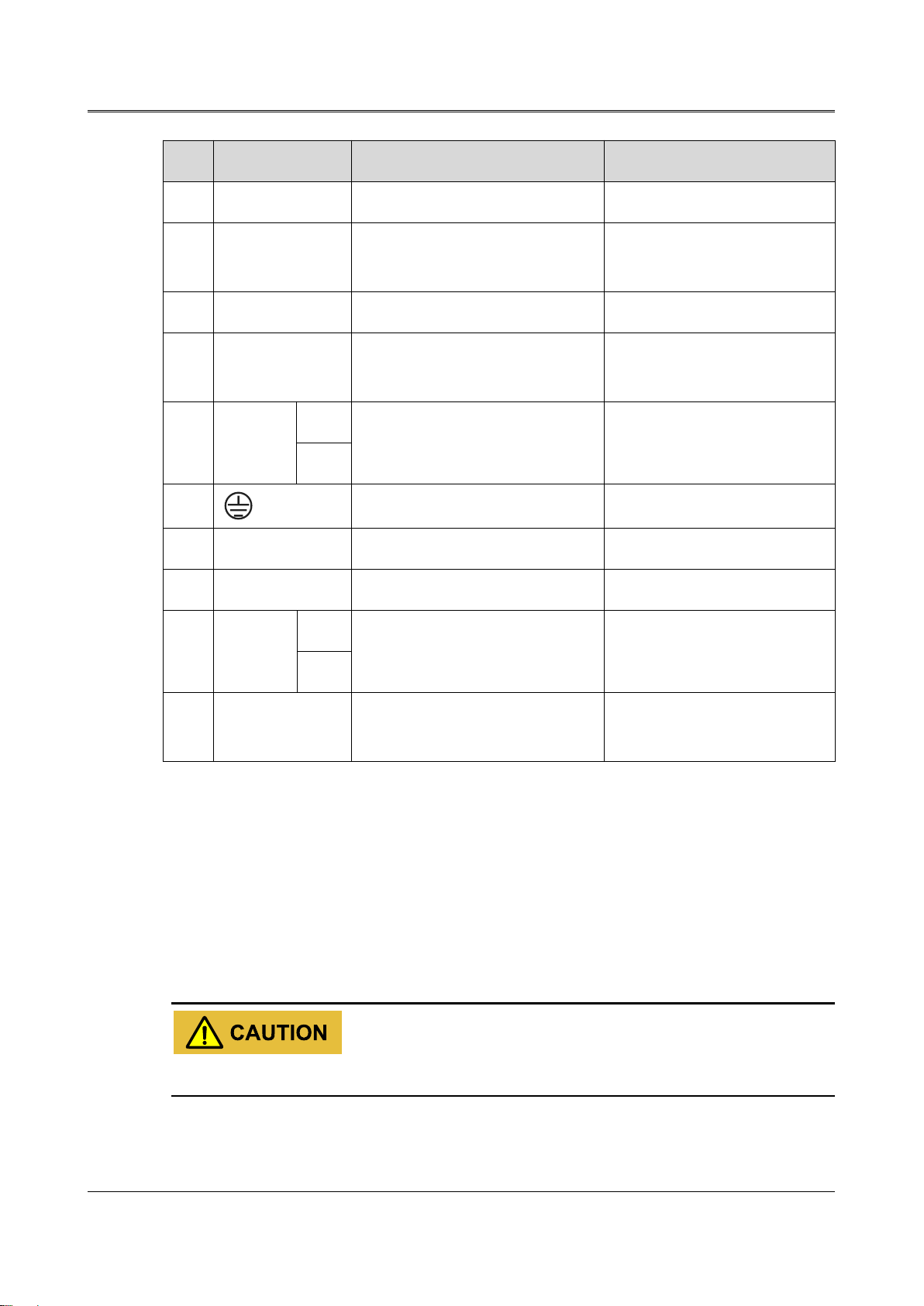
Table2-2 Inverter terminals illustration
NO.
Mark
Illustration
Remarks
①
Meter1/ Meter2
Monitor grid side power.
Meter1 and Meter 2 are the
same portal.
Energy Storage System iHome-INV Series
User Manual
2 Overview
13
NO.
Mark
Illustration
Remarks
②
DRM
Inverter demand response modes.
\
③
BMS
Connect to COM port of battery to
communicate with battery.
\
④
Parall1/Parall2
Have parallel function.
Reserved
⑤
WIFI/4G
It is used for WIFI/4G
communication.
\
⑥
BATT.
+
DC input terminal
It is used to connect with
battery.
-
⑦
Grounding port
External grounding port.
⑧
GRID
AC output terminal
It is used to connect with grid.
⑨
BACKUP
AC output terminal
It is used to connect with load.
⑩
PV1/PV2
+
DC input terminal
It is used to connect with PV.
-
⑪
DC switch
DC switch
Can be removed under specific
market requirements.
DC switch
DC switch (as shown in the⑪of Figure2-2) is the connection switch between inverter and PV array.
During installation and wiring, the DC switch must be OFF.
Before maintenance, the DC switch must be OFF, and 5 minutes after the indicator is off, the
maintenance can be done.
When maintenance or wiring, the DC switch must be disconnected.
2 Overview
Energy Storage System iHome-INV Series
User Manual
14
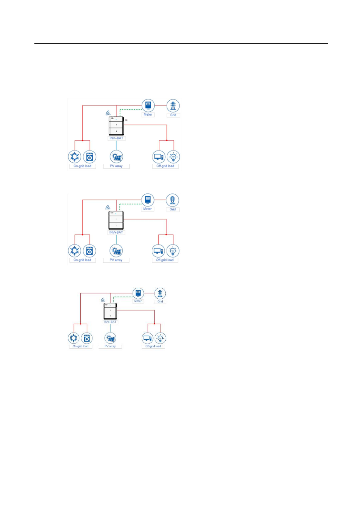
2.3 Application Scenarios
The energy storage system iHome-INV series can be applied in DC-coupled system, AC-coupled
system and fully off-grid system, as shown in Figure2-3, Figure2-4 and Figure2-5.
Figure2-3 DC-coupled system
Figure2-4 AC-coupled system
Figure2-5 Fully off-grid system
This manual suits for next models
3
Table of contents
Other Chelion Inverter manuals


Popular Inverter manuals by other brands


Briggs & Stratton
Briggs & Stratton 190732GS owner's manual

PAV
PAV BI2000 owner's manual

Grape Solar
Grape Solar GS-900-PH-KIT Quick connect guide

Link electronics
Link electronics Genflex 812-OP/G Specification sheet

Victron energy
Victron energy MultiPlus 12/5000/200-100 230V user manual

Hitachi
Hitachi SJ100 Series instruction manual