Chelion iHome-INV3K-6K-L1h02 User manual

iHome-INV3K-6K- L1h02
User Manual

Contents
1. Safety Introductions
2. Product instructions
2.1
Product Overview and Size
2.2
Product Features
2.3
Basic System Architecture
2.4
Maintenance of the System
⋯⋯⋯⋯⋯⋯⋯⋯⋯⋯⋯⋯⋯⋯⋯⋯⋯⋯ 01
⋯⋯⋯⋯⋯⋯⋯⋯⋯⋯⋯⋯⋯⋯⋯⋯⋯⋯ 01-06
3. Installation
3.1
Parts list
⋯⋯⋯⋯⋯⋯⋯⋯⋯⋯⋯⋯⋯⋯⋯⋯⋯⋯⋯⋯⋯⋯⋯ 07-20
3.2
Mounting instructions
3.3
Battery connection
3.4
Grid connection and backup load connection
3.5
PVConnection
3.6
CTConnection
3.6.1
Meter Connection
3.7
Earth Connection(mandatory)
3.8
WIFI Connection
3.9
Wiring System for Inverter
4. OPERATION
4.1
Power ON/OFF
⋯⋯⋯⋯⋯⋯⋯⋯⋯⋯⋯⋯⋯⋯⋯⋯⋯⋯⋯⋯⋯⋯⋯ 21
4.2
Operation and Display Panel
5. LCD Display Icons
5.1
Main Screen
5.2
Solar Power Curve
⋯⋯⋯⋯⋯⋯⋯⋯⋯⋯⋯⋯⋯⋯⋯⋯⋯⋯⋯⋯ 22-35
5.3
Curve Page-Solar & Load & Grid
5.4
System Setup Menu
5.5
Basic Setup Menu
5.6
Battery Setup Menu
5.7
System Work Mode Setup Menu
5.8
Grid SetupMenu
5.9
Generator Port Use Setup Menu
5.10
Advanced Function Setup Menu
5.11
Device Info Setup Menu
6. Mode ⋯⋯⋯⋯⋯⋯⋯⋯⋯⋯⋯⋯⋯⋯⋯⋯⋯⋯⋯⋯⋯⋯⋯⋯⋯⋯ 35-37
7. Fault information and processing ⋯⋯⋯⋯⋯⋯⋯⋯⋯⋯⋯⋯⋯ 37-40
8. Limitation of Liability ⋯⋯⋯⋯⋯⋯⋯⋯⋯⋯⋯⋯⋯⋯⋯⋯⋯⋯⋯ 40
9. Datasheet ⋯⋯⋯⋯⋯⋯⋯⋯⋯⋯⋯⋯⋯⋯⋯⋯⋯⋯⋯⋯⋯⋯⋯⋯ 41-42
10. Package and transport inverter ⋯⋯⋯⋯⋯⋯⋯⋯⋯⋯⋯⋯⋯⋯ 42

11. Disposing of the inverter ⋯⋯⋯⋯⋯⋯⋯⋯⋯⋯⋯⋯⋯⋯⋯⋯⋯ 42
12. Appendix I
13. Appendix II
⋯⋯⋯⋯⋯⋯⋯⋯⋯⋯⋯⋯⋯⋯⋯⋯⋯⋯⋯⋯⋯⋯⋯ 43-44
⋯⋯⋯⋯⋯⋯⋯⋯⋯⋯⋯⋯⋯⋯⋯⋯⋯⋯⋯⋯⋯⋯⋯ 45

- 01 -
About This Manual
The manual mainly describes the product information, guidelines for installation, operation and
maintenance. The manual cannot include complete information about the photovoltaic (PV)
system.
How to Use This Manual
Read the manual and other related documents before performing any operation on the inverter.
Documents must be stored carefully and be available at all times.
Contents may be periodically updated or revised due to product development. The information
in this manual is subject to change without notice.
1. Safety Introductions
·This chapter contains important safety and operating instructions. Read and keep thismanual
for future reference.
·Before using the inverter, please read the instructions and warning signs of the battery and
corresponding sections in the instruction manual.
·Do not disassemble the inverter. If you need maintenance or repair, take it to a professional
service center.
·Improper reassembly may result in electric shock or fire.
·To reduce risk of electric shock, disconnect all wires before attempting any maintenance or
cleaning. Turning off the unit will not reduce this risk.
·Caution: Only qualified personnel can install this device with battery.
·Never charge a frozen battery.
·For optimum operation of this inverter, please follow required specification to select appropriate
cable size. It is very important to correctly operate this inverter.
·Be very cautious when working with metal tools on or around batteries. Dropping a tool may
cause a spark or short circuit in batteries or other electrical parts, even cause an explosion.
·Please strictly follow installation procedure when you want to disconnect AC or DC terminals.
Please refer to "Installation" section of this manual for the details.
·Grounding instructions - this inverter should be connected to a permanent grounded wiring
system. Be sure to comply with local requirements and regulation to install thisinverter.
·Never cause AC output and DC input short circuited. Do not connect to the mains whenDC
input short circuits.
2. Product Introductions
This is a multifunctional inverter, combining functions of inverter, solar charger and battery
charger to offer uninterruptible power support with portable size. Its comprehensive LCD display
offers user configurable and easy accessible button operation such as battery charging, AC/solar
charging, and acceptable input voltage based on different applications.

- 02 -
1
2
3
4
5
6
1 2
8
7
11
18
9
10
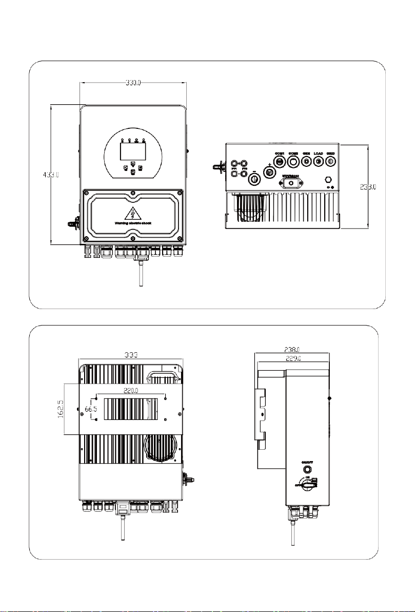
2.1 Product Overview and Size
iHome-INV(3-5)k-L1H02
1: Inverter Indicators
2: LCD display
3: Function Buttons
4: Battery inputconnectors
5: RS485/CAN Port
6: Meter Port
7: Function Port
8: Parallel port
9: Generator input
10: Load
11: Grid
12: Power on/off button
13: DC Switch
14: PV input with two MPPT
15: Battery
16: Temperature sensor
17: WiFi Interface
18: DRM Port
12
13
14
15
16
17
- 03 -
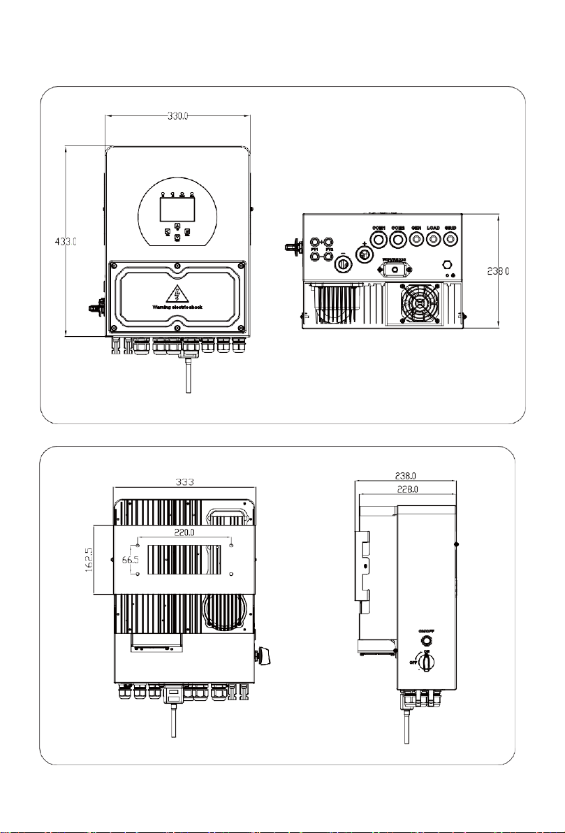
iHome-INV(3-5)k-L1H02
Inverter Size

iHome-INV6k-L1H02
- 04 -
1: Inverter Indicators
2: LCD display
3: Function Buttons
4: Battery inputconnectors
5: RS485/CAN Port
6: Meter Port
7: Function Port
8: Parallel port
9: Generator input
10: Load
11: Grid
12: DC Switch
13: PV input with two MPPT
14: Battery
15: Temperature sensor
16: WiFi Interface
17: Fan
18: DRM Port
1
2
3
4
5
6
8
1 2
7
11
18
9
10
12
13
14
15
16
17
- 05 -
Inverter Size
- 06 -
2.2 Product Features
-Self-consumption and feed-in to the grid.
-Auto restart while AC is recovering.
-Programmable supply priority for battery or grid.
-Programmable multiple operation modes: On grid, off grid and UPS.
-Configurable battery charging current/voltage based on applications by LCD setting.
-Configurable AC/Solar/Generator Charger priority by LCD setting.
-Compatible with mains voltage or generator power.
-Overload/over temperature/short circuit protection.
-Smart battery charger design for optimized battery performance
-With limit function, prevent excess power overflow to the grid.
-Supporting WIFI monitoring and build-in 2 strings of MPP trackers
-Smart settable three stages MPPT charging for optimized battery performance.
-Time of usefunction.
-Smart LoadFunction.
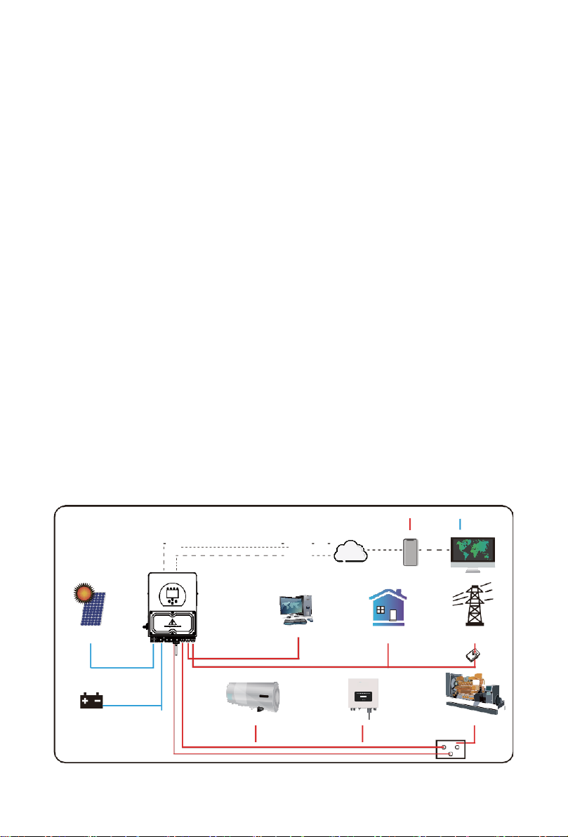
2.3 Basic System Architecture
The following illustration shows basic application of this inverter.
It also includes following devices to have a Complete running system.
-Generator or Utility
-PV modules
Consult with your system integrator for other possible system architectures depending on your
requirements.
This inverter can power all kinds of appliances in home or office environment, including motor
type appliances such as refrigerator and air conditioner.
2.4 Maintenance of the System
The inverter is low maintenance, however, it is important that at least twice a year (for dusty
environments this may need to be carried out weekly) all the cooling fans, air ducts are cleaned
and dust free.Check if there are no fault codes and Lithium battery communication is correct.
Weekly cleaning statement:Suggest micromesh filters as an available option.
Cloud services phone
Solar
Backup Load
On-Grid Home Load
Grid
CT
AC cable DC cable
WiFI
GPRS
Battery
Smart Load
Grid-connected Inverter
Generator
ATS
- 07 -
3. Installation
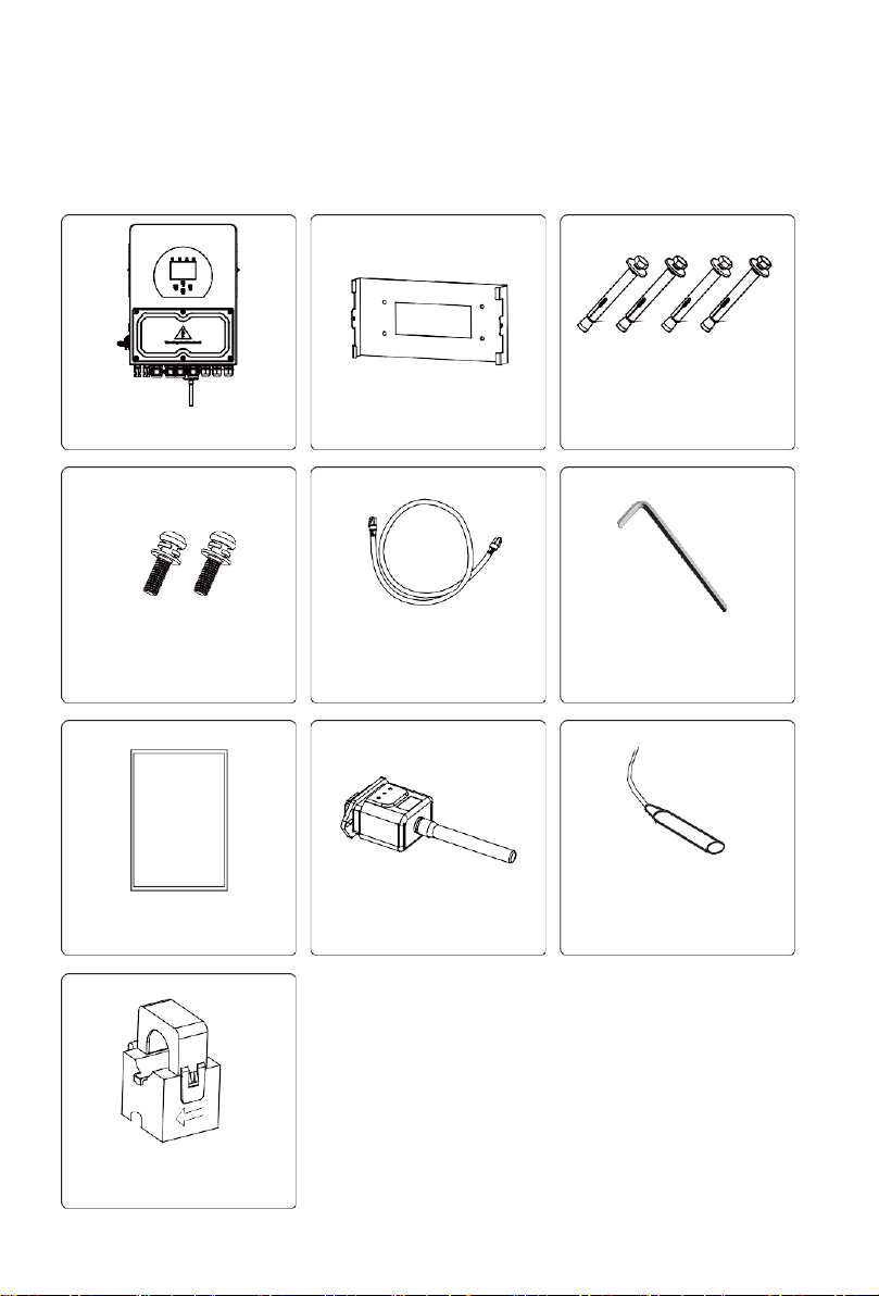
3.1 Parts List
Check the equipment before installation. Please make sure nothing is damaged in the package.
You should have received the items in the following package:
Hybrid inverter
x1
Wall mounting bracket x1
Stainless steel anti-collision
bolt M8×80
x4
Stainless steel mounting
screws M6*12 x2
Parallel communication
cable x1
L-type Hexagon wrench
x1
User manual x1
User
manual
Wi-Fi-Plug(optional) x1
Battery temperature sensor
x1
Sensor Clamp
x 1
- 08 -
3.2 Mounting instructions
Installation Precaution
This Hybrid inverter is designed for outdoor use(IP65), Please make sure the installation site
meets below conditions:
·Not in direct sunlight
·Not in areas where highly flammable materials are stored.
·Not in potential explosive areas.
·Not in the cool air directly.
·Not near the television Antenna or antenna cable.
·Not higher than altitude of about 2000 meters above sea level.
·Not in environment of precipitation or humidity(>95%)
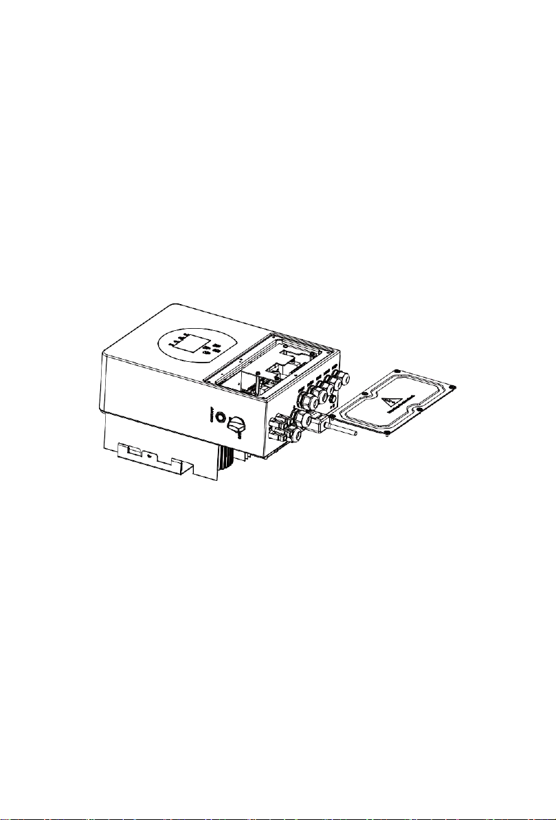
Please AVOID direct sunlight, rain exposure, snow laying up during installation and
operation. Before connecting all wires, please take off the metal cover by removing
screws as shown below:
Considering the following points before selecting where to install:
·Please select a vertical wall with load-bearing capacity for installation, suitable for installation
on concrete or other non-flammable surfaces,installation is shownbelow.
·Install this inverter at eye level in order to allow the LCD display to be read at alltimes.
·The ambient temperature is recommeded to be between -40~60℃to ensure optimal operation.
·Be sure to keep other objects and surfaces as shown in the diagram to guarantee sufficient
heat dissipation and have enough space for removing wires.

- 09 -
≥500mm
≥500mm
For proper air circulation to dissipate heat, allow a clearance of approx. 50cm to the side and
approx. 50cm above and below the unit. And 100cm to the front.
Mounting the inverter
Remember that this inverter is heavy! Please be careful when lifting out from the package.
Choose the recommend drill head(as shown in below pic) to drill 4 holes on the wall,
82-90mm deep.
1. Use a proper hammer to fit the expansion bolt into the holes.
2.Carry the inverter and holding it, make sure the hanger aim at the expansion bolt,fix the
inverter on the wall.
3. Fasten the screw head of the expansion bolt to finish the mounting.

- 10 -
Inverter hanging plate installation
3.3 Battery connection
For safe operation and compliance, a separate DC over-current protector or disconnect device is
required between the battery and the inverter. In some applications, switching devices may not
be required but over-current protectors are still required. Refer to the typical amperage in the
table below for the required fuse or circuit breaker size.
Model
Wire Size
Cable(mm 2)
Torque value(max)
3/3.6/5/6Kw
2AWG
35
5.2Nm
Chart 3-2 Cable size
- 11 -
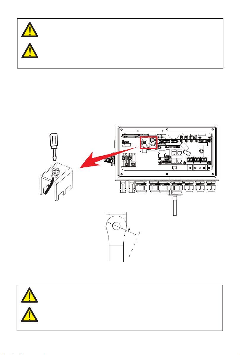
Please follow below steps to implement battery connection:
1.Please choose a suitable battery cable with correct connector which can well fit intothe
battery terminals.
2. Use a suitable screwdriver to unscrew the bolts and fit the battery
connectors in, then fasten the bolt by the screwdriver, make sure the bolts are tightened
with torque of 5.2 N.M in clockwise direction.
3. Make sure polarity at both the battery and inverter iscorrectly
connected.
For 3KW/3.6KW/5KW/6KW
DC Battery Input
4.In case of children touch or insects go into the inverter, Please make sure the inverter
connector is fasten to waterproof position by twist it clockwise.
All wiring must be performed by a professional person.
Connecting the battery with a suitable cable is important for safe and efficient
operation of the system. To reduce the risk of injury, refer to Chart 3-2 for
recommended cables.
model, battery connector screw size: M6
24mm
Installation must be performed with care.
Before making the final DC connection or closing DC breaker/disconnect, be sure
positive(+) must be connect to positive(+) and negative(-) must be connected to
negative(-). Reverse polarity connection on battery will damage the inverter.

- 12 -
3.3.2 Function port definition
ON
1 2
DIP Switch
Inverter
TEMP:1,2
CT:3,4
G-start:5,6
G-valve:7,8
L ATS240V N
1 2 3 4 5 6 7 8
RS485/CAN Meter
parallel_1 parallel_2
DRM
BattTemp
Sensor
CT Coil
Genstart-up
N/ORelay
RS485/CAN: CAN port for battery
communication.
Meter: forenergymetercommunication.
Parallel 1: Parallel communication port 1
(
CAN interface
).
Parallel 2: Parallel communication port 2
(
CAN interface
).
TEMP(1,2): battery temperature sensor for
lead acid battery.
CT(3,4): current transformer for "zero export
to CT" mode.
DRM port:Logic interface for
AS/NZS 4777.2:2020
G-start/G-valve(5,6/7,8): dry contact signal for startup the
diesel generator.
When the "GEN signal" is active, the open
contact(GV/GS)willswitchon(novoltageoutput).If the"SignalISLANDMODE"is ticked, the GS
port will be the dry contact signal for startup the diesel generator.If "Signal ISLAND MODE"
is not ticked, the GV port will be the dry contact signal for startup the diesel generator.
ATS: 230V output port when inverter is on.
DIP switch: Parallel communication resistor
If the number of inverters in the parallel system
is less than or equal to 6, all inverter’s DIP
switch (1&2) need be ON position.
If the number of inverters in parallel system
coil
open
contact
G
GV/GS
relay
V/S
ON
1 2

- 13 -
exceeds 6, the main 6pcs inverter’s DIP switch
needs to be ON position. And the other
inverter DIP switch (1&2) needs to be OFF position.
(diesel generator startup signal)
- 14 -
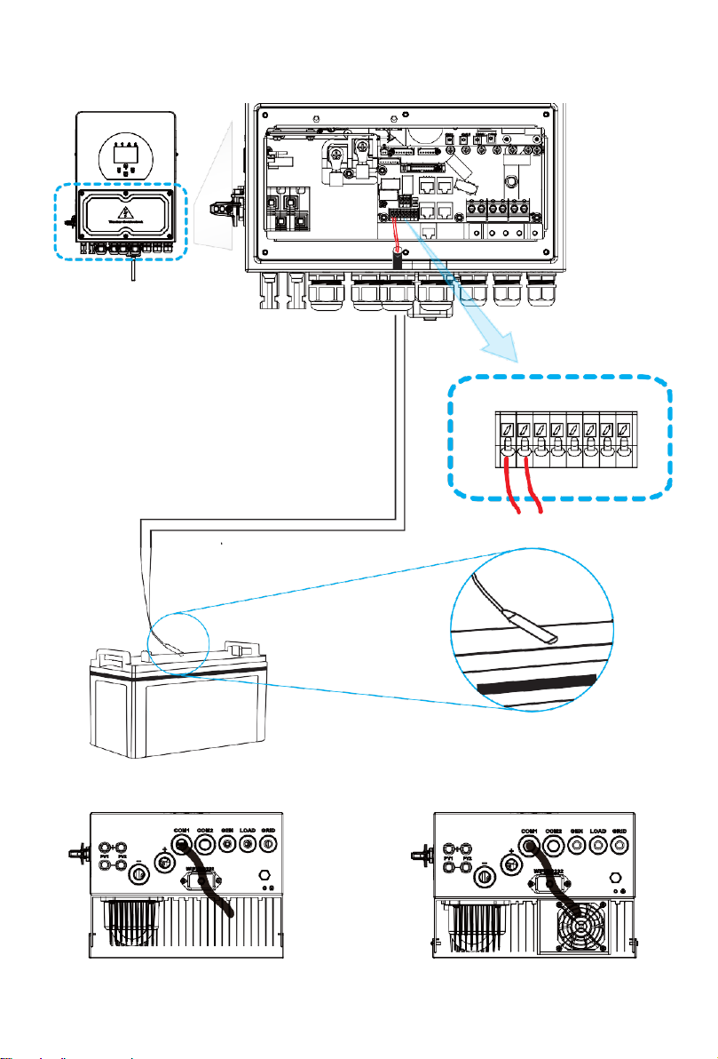
3.3.3 Temperature sensor connection for lead-acid battery
ON
1 2
Inverter
1 2
Temp. sensor
iHome-INV(3-5)k-L1H02 iHome-INV6k-L1H02

- 15 -
3.4 Grid connection and backup load connection
·Before connecting to the grid, a separate AC breaker must be installed between the inverter
and the grid, and also between the backup load and the inverter. This will ensure the inverter
can be securely disconnected during maintenance and fully protected from over current. For
the 3/3.6/5/6KW model, the recommended AC breaker for backup load is 40A. For the3/3.6/
5/6KW model, the recommended AC breaker for grid is 40A. In final installation, breaker certified
according to AS60947.3 shall be installed with the equipment.
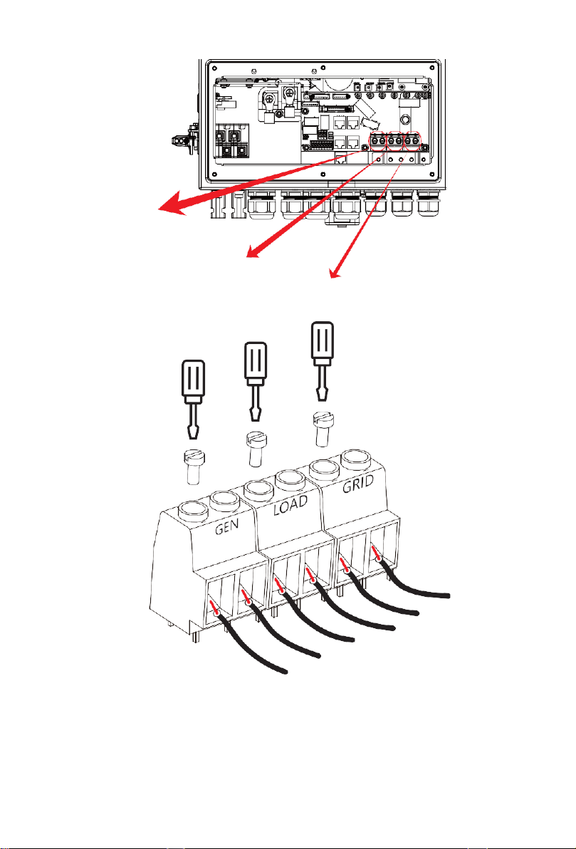
·There are three terminal blocks with "Grid" "Load"and "GEN" markings. Please do not misconnect
input and output connectors.
Model
Wire Size
Cable(mm 2)
Torque value(max)
3Kw
10AWG
4
1.2Nm
3.6Kw
10AWG
6
1.2Nm
5Kw
10AWG
6
1.2Nm
6Kw
8AWG
8
1.2Nm
Chart 3-3 Recommended Size for AC wires
Please follow below steps to implement AC input/output connection:
1.Before making Grid, load and Gen port connection, be sure to turn off AC breakeror
disconnector first.
2.Remove insulation sleeve 10mm length, unscrew the bolts, insert the wires according to
polarities indicated on the terminal block and tighten the terminal screws. Make sure the
connection is complete.
All wiring must be performed by a qualified personnel.It is very important for
system safety and efficient operation to use appropriate cable for AC input
connection. To reduce risk of injury, please use the proper recommended cable
as below.
- 16 -
ON
1 2
GEN PORT
LOAD
GRID
N
N L
L
N
L

- 17 -
3.Then, insert AC output wires according to polarities indicated on the terminal block and tighten
terminal. Be sure to connect corresponding N wires and PE wires to related terminals as well.
4. Make sure the wires are securely connected.
5.Appliances such as air conditioner are required at least 2-3 minutes to restart because it is
required to have enough time to balance refrigerant gas inside of circuit. If a power shortage
occurs and recovers in short time, it will cause damage to your connected appliances. To
prevent this kind of damage, please check manufacturer of air conditioner if it is equipped with
time-delay function before installation. Otherwise, this inverter will trigger overload fault and
cut off output to protect your appliance but sometimes it still causes internal damage to the air
conditioner
3.5 PV Connection
The PV modules used to connected to this inverter shall be Class A rating certified according
to lEC 61730.
Before connecting to PV modules, please install a separately DC circuit breaker between
inverter and PV modules. It is very important for system safety and efficient operation to
use appropriate cable for PV module connection. To reduce risk of injury, please use the
proper recommended cable size as below.
Model
Wire Size
Cable(mm )
3/3.6/5/6Kw
12AWG
4
Chart 3-4 Cable size
3.5.1 PV Module Selection:
When selecting proper PV modules, please be sure to consider below parameters:
1)Open circuit Voltage (Voc) of PV modules not exceeds max. PV array open circuit voltage of
inverter.
2) Open circuit Voltage (Voc) of PV modules should be higher than min. start voltage.
Be sure that AC power source is disconnected before attempting to wire it to the
unit.
To avoid any malfunction, do not connect any PV modules with possible current
leakage to the inverter. For example, grounded PV modules will cause current
leakage to the inverter. When using PV modules, please ensure the PV+ & PV-
of solar panel is not connected to the system ground bar.
It is requested to use PV junction box with surge protection. Otherwise, it will
cause damage on inverter when lightning occurs on PV modules.
Table of contents
Other Chelion Inverter manuals


Popular Inverter manuals by other brands

Alpha
Alpha 6000S series user manual

SunSynk
SunSynk SUNSYNK-8K-SG01LP1 user manual

Chromalox
Chromalox CMB-3A Installation, operation and renewal parts identification

Hayward
Hayward Salt&Swim SAS-AU owner's manual

Goodwe
Goodwe TURBO ENERGY Lithium Series Quick installation guide

Powtran
Powtran PI500A-S Series manual


