Chell TP9000CI User manual


Page1
Please read thismanual carefullybefore using the instrument.
Use of this equipment in a manner not specified in this
manual may impair the user’s protection.
Chell Document No. : 900255Issue 1.0
ECO : ---- Date:15th August 2023
Chell’s policyof continuously updating andimproving productsmeans that
this manual maycontain minor differencesin specification, components and
software design fromthe actualinstrument supplied.

Page2
CONTENTS
1Description ..............................................................................................................................3
1.1 Introduction........................................................................................................................ 3
Specification...................................................................................................................................4
2.1 Power Supply:.................................................................................................................... 4
2.2 Package:............................................................................................................................ 4
2.3 Ethernet Specifications:..................................................................................................... 4
2.4 Operating conditions:......................................................................................................... 4
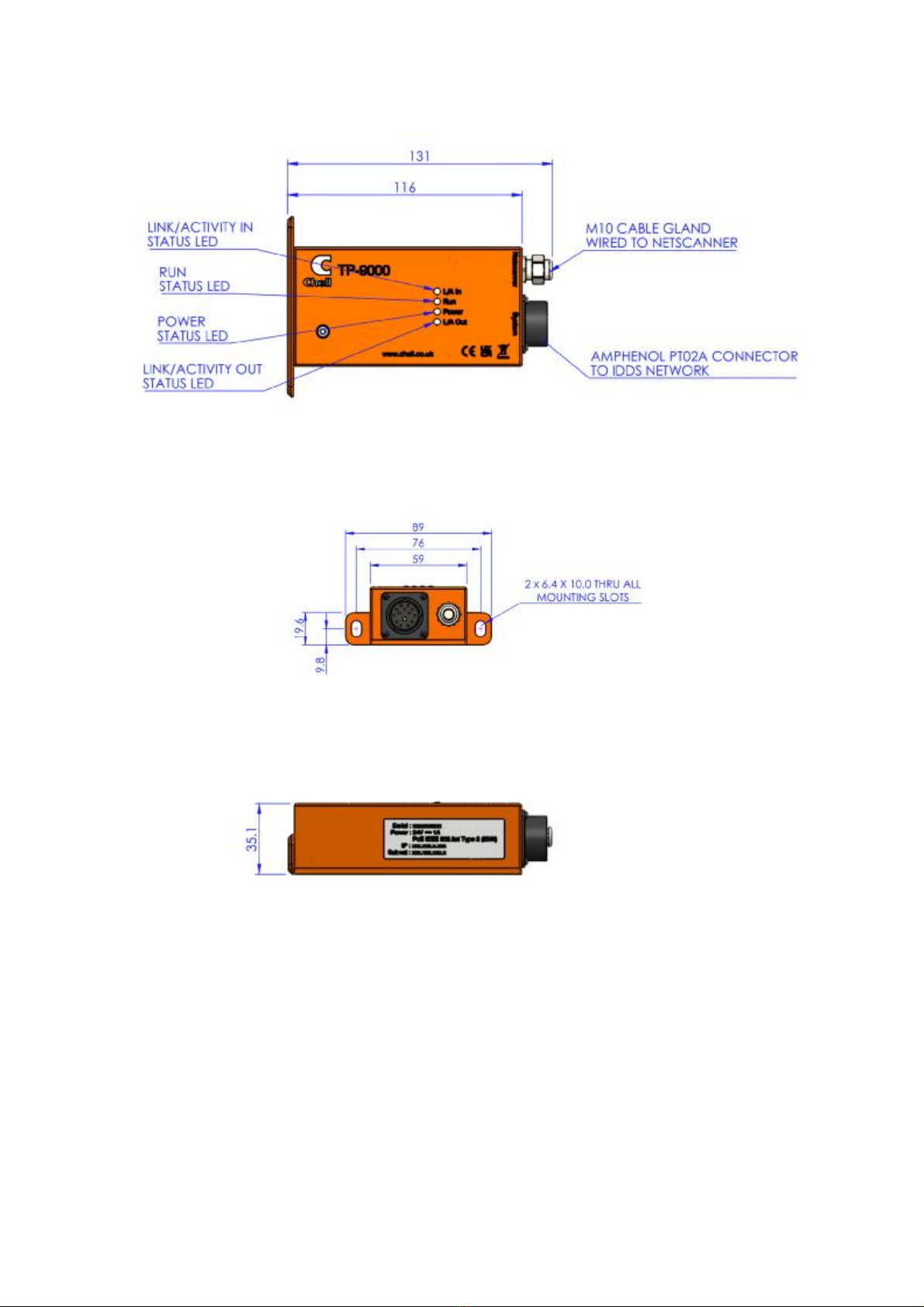
2.5 Dimensions ........................................................................................................................ 5
3Installation and Interconnections......................................................................................... 6
3.1 Wiring – Power & comms .................................................................................................. 6
3.1.1 TP9000 Power Supply................................................................................................ 6
3.1.2 MIL-DTL-26482 Series I Mating Connector (PT06A14-15S)..................................... 6
3.1.3 OptionalM12 Mating Connector (recommended cable of type 'Harting 09478411002
or equivalent)............................................................................................................................ 6
3.2 Mounting Holes.................................................................................................................. 7
4TP9000 Webserver..................................................................................................................8
4.1 Introduction. ....................................................................................................................... 8
4.2 Common Controls Sidebar................................................................................................ 9
4.3 The 'Setup'Page............................................................................................................... 9
4.3.1 Introduction................................................................................................................. 9
4.3.2 Data Streaming........................................................................................................... 9
4.3.3 GeneralEthernet Comms......................................................................................... 10
4.3.4 NetScanner Comms ................................................................................................. 11
4.3.5 UDP Specific Comms............................................................................................... 11
4.4 'Live Data' Page............................................................................................................... 12
4.5 ‘Channel Info’ Page......................................................................................................... 12
4.6 ‘Advanced’ Page.............................................................................................................. 13
4.6.1 Time Stamping......................................................................................................... 13
4.6.2 Live Health Check .................................................................................................... 13
5Service and Calibration ........................................................................................................14
5.1 Service............................................................................................................................. 14
5.2 Calibration........................................................................................................................ 14
5.3 Adjustment....................................................................................................................... 14
5.4 Cleaning........................................................................................................................... 14

Page3
1Description
1.1Introduction
The Chell TP9000CIis atranslator designed tobeusedwith Measurement
Specialties NetScanner9x16 devices, whichhave Ethernet communications but
do notnativelysupporttheChell and IENA streamingprotocols.Itis basedaround
the original TP9000that wasdesignedfor adding theDDS protocol to NetScanner
devices.
The TP9000CI is asmall device thatis designedto attach totheside of the
NetScanner and communicate directly with it, providingan Ethernet interface to
command the NetScanner to streamdata and switch valves andread back the
data from the NetScanner, converting it toaChell or IENA formatteddatastream
that is transmitted over TCP/UDP as appropriate.
Configuration is provided via an embeddedwebserver whichcanalsobeusedas
an information/debugtool tocheck that thedevice is correctly communicating with
the NetScanner.

Page4
Specification
2.1Power Supply:
DC Supply
18 to 48VDC
Maximumcurrent consumption:18 VDC supply: 1400mA
48 VDC supply: 520mA
PoE : See section3.1.1
2.2Package:
Dimensions
128
x
60
x
36
mm
Weight
380g
2.3Ethernet Specifications:
TCP/IP 10Mb/s & 100Mb/s viaAuto Negotiation
TCP
andUDP
protocols supported
2.4Operating conditions:
Operating temperaturerange: -55°C to +90°C
Storage temperature range: -55°C to +90°C
MaximumRelative humidity: 95% at 50°C (non condensing)
MIL-DTL-26482
PT06A14-15S
Page5
2.5Dimensions

Page6
3Installation and Interconnections
3.1Wiring – Power & comms
3.1.1 TP9000 Power Supply
The TP9000 is equipped with anauxiliary DCpower supply and aPower-over-
Ethernet supply. TheDCsupplywill takepriority soaTP9000poweredupover DC
will not negotiatewith aPoEswitch.IftheDCsupply is removed, thentheTP9000
will establish a power supply froma PoE switch if it is present.
If however theTP9000is poweredvia PoEand aDC supply thembecomes
available,theTP9000 will switch all its powerconsumption over to the DC supply.
The power supply source detectedatstart-up is displayedonthe embedded
webserver for information purposes.
3.1.2 MIL-DTL-26482 Series I Mating Connector (PT06A14-15S)
Recommend use :DC supply and PoEType 1, 2.
Pin Number
Designation
A Ethernet RX+
B Ethernet TX+
C Ethernet TX-
D Trigger IN
E Trigger REF
N Ethernet RX-
P Power Supply +Vdc
R Power Supply Return(0V)
3.1.3 Optional M12 Mating Connector (recommended cable of type 'Harting
09478411002 orequivalent)
Recommend use :PoE Type 1, 2.
Pin Number
Colour Code
1 1 DA+ (TX+)
2 2 DA- (TX-)
3 3 DB+ (RX+)
4 4 DB- (RX-)
5 5 DD+
6 6 DD-
7 7 DC-
8 8 DC+
Page7
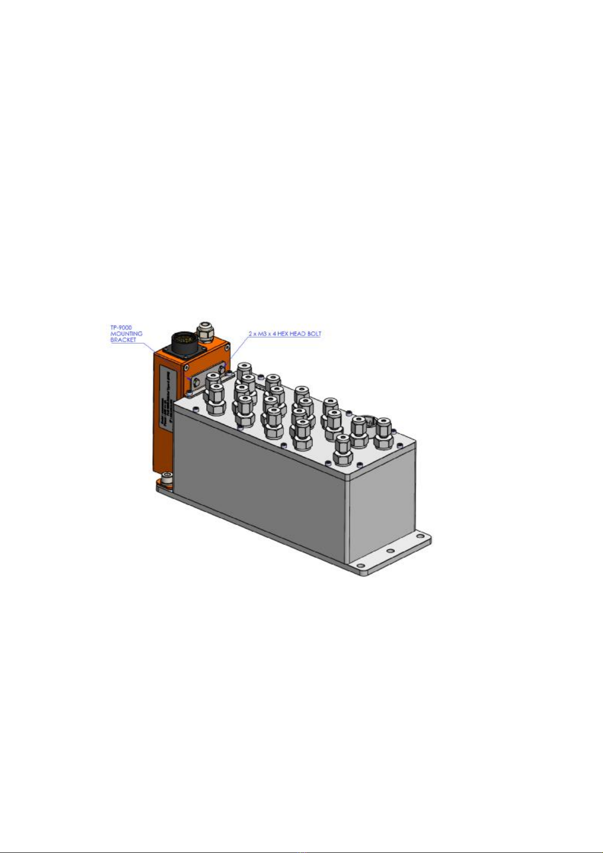
3.2Mounting Holes.
The TP9000 has 2 slotted mounting holes that line up with theouter mounting
holes on the NetScanner. The TP9000 is designed tofit on either side of the
NetScanner product and has an optional mounting bracket whichcan be used in
high vibration environments. This bracketis fitted to the TP9000 with two M3 hex
bolts asshownbelow. To mount the bracket to the NetScanner, two of the bolts
must be removedfrom the topplate of the scanner. These bolts arethen passed
through the mountingbracket as shown below.
NOTE : It is important that the sealing‘O’ which is present on the NetScanner top
plate bolts is moved to below the TP9000mounting bracket to maintain the
sealing integrity of the NetScanner.
Page8
4TP9000Webserver
4.1Introduction.
In keepingwith other devices fromChell containing an embeddedwebserver, the
TP9000includes some pages thatcontainconfigurationparameters as well as
information/debugpages.
The webserver is divided by tabs intofive areas of functionality,namely 'Setup’,
'Live Data', 'Channel Info', ‘Advanced’ and ‘Factory Tools’.
'Setup’ provides the means tosee the currentstreamingrate and commssetupfor
boththeTP9000unit and theconnectedNetScanner device. The unit's function
may bechecked and demonstrated using 'LiveData' toshow the current pressure
and temperature readings fromthe attachedNetScanner. ‘Channel Info’ shows the
configuredrangeofeachtransducer ofthe connectedNetScanner device.
‘Advanced’ has extra functions &informationthatmost users probably do not need
butmightbenecessary for other users. ‘Factory Tools’ ispassword protected,but
simply provides accessto theserial number and manufacture dateof theTP9000.
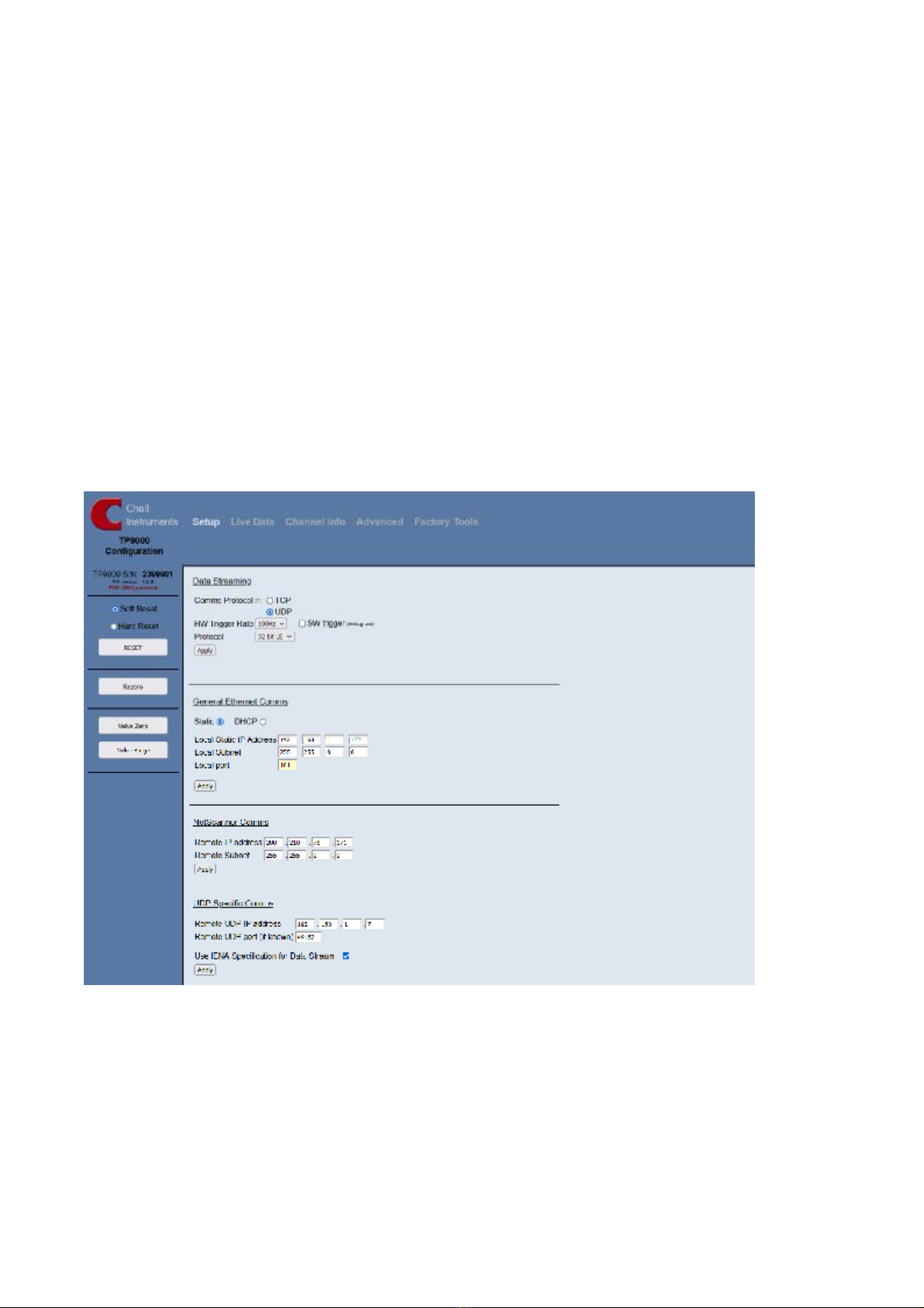
Figure 4.1, Main Setup page

Page9
4.2Common Controls Sidebar
4.3The 'Setup' Page
4.3.1 Introduction
The 'Setup’ pageshowsall of theTP9000’s main operatingparameters. Setup is
divided into differentcategories by function, and eachcategory is detailed
separately in the following.
4.3.2 Data Streaming
The ‘DataStreaming’sectionshowstherateconfiguredfor datastreamingfrom
the attachedNetScanner. For timingsynchronisation purposes,in general usethis
is always ahardwaretriggereddatastream,with thetrigger internally generated
by the TP9000. TheCommsProtocol dictatesthe transport layer protocol used for
the datastreamingoutput.If IENA specification is required, this must beset to
UDP. Theprotocol shows theendianness formatsettingfor thedatastreamed
output.
Figure 4.2, Data SteamingSetup section
Figure 4.1 above shows the first page viewed when
navigating to the webserver. The menu at thetop allows the
user to choosewhat is visible in the central window, and the
sidebar (shown left) shows information andalso provides a
means to reset the unit.
Ahard reset will restart the oprerating system within the
TP9000 and is requiredwhen changing theIPaddress of the
unit. Asoftreset simply restarts the application andis
therefore significantly quicker and best used to actually use
other applied settings after they have been changed.
There are also two command functions provided to operate
the valving within theNetScanner to performaZero orPurge
function acccordingly.
Page10
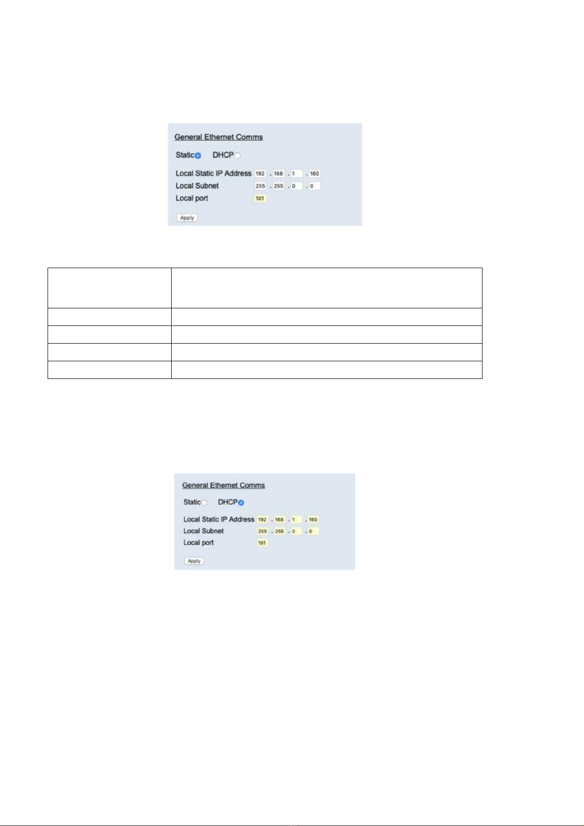
4.3.3 General Ethernet Comms
The General Ethernet Commsparameters areshown in Figure 4.3. The options in
this section control the TP9000’s IP address, subnet mask andLocal port.
Figure 4.3a, TCP Commsgroup
‘Static’& ‘DHCP’ radio
buttons
Toggle between a statically set IP address (using the text boxes
below), or adynamically assigned IPaddress (from an external
DHCP server)
'IP Address' IP address allocated to TP9000on the user's network.
'Subnet' Subnet mask as set on theuser's network.
‘Local port’ Local port of the device (fixed to101).
‘Apply’ Applies the settings tothelocal memory
Table 3.1, TCP Commsgroup settings
When DHCP is selected by clicking theradio button, thei/p address and subnet
address cannot be edited, as shown below.
Figure 4.3b, DHCP Comms
Page11
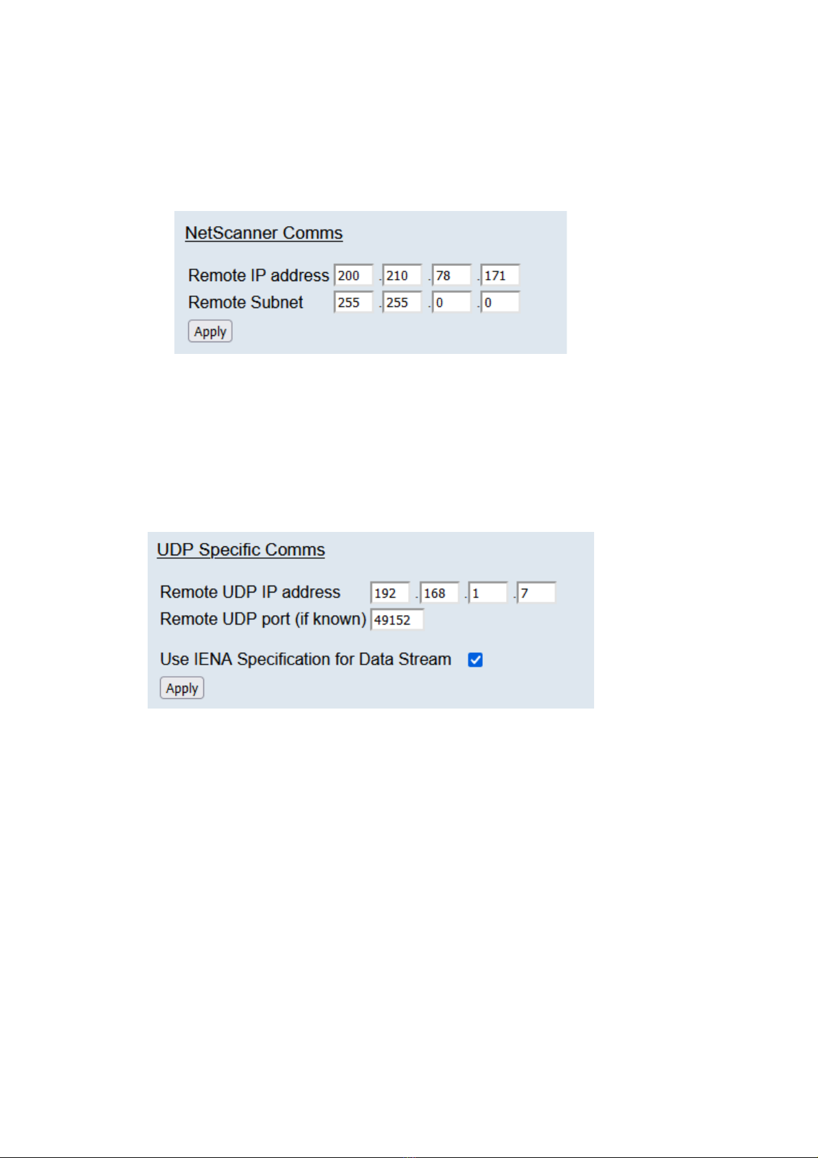
4.3.4 NetScanner Comms
The NetScanner Commssection shows the IP address and Subnet of the
connected NetScannerunit (as shown in Figure 4.4). This is set by the factory
initially when the TP9000 is connected to the NetScanner and should not be
changed unlessthe TP9000 unitis moved to a different NetScanner.
Figure 4.4, NetScanner Comms section
4.3.5 UDP Specific Comms
This section allows for configuration of the remotehost’s UDP address andport so
thattheTP9000knowswheretoautomatically startstreamingdatato onpower up
(assumingthe data rateis not set to ‘Off’). Thisis also thesectionwhere the IENA
specification can be selected for the datastreamoutput.
Figure 4.5, UDPSpecificComms section

Page12
4.4'LiveData' Page
Figure 4.6 shows the 'Live Data' page of the webserver.
Figure 4.6, Live Data Page
The livedatapageisameans todemonstrating thecorrect operation of TP9000
and essentially confirms communicationwith the attachedNetScanner. The page
shows boththepressure (in psi) and temperature (indegreesC) for eachchannel
as reported by the NetScanner.
4.5‘Channel Info’ Page
The 'Channel Info' page shows asummaryof the range configured for each
transducer ofthe connectedNetScanner, as reported at systeminitialisation.
Figure 4.7, ‘Channel Info’ Page

Page13
4.6‘Advanced’Page
The advancedpagecontains informationontimestampingandsystem health
check readings.
4.6.1 Time Stamping
This section shows thesettings for thetimestampingwithin theTP9000. This
timestamp will allow theuser to get microsecond level accuracytimestamps onthe
datapackets.
Figure 4.8, Timestampingsection
‘PTP synchronisation on’
checkbox
This shows whether timestamps arePTP synchronised or
not. Please note this will only work if there is a PTP
grandmaster clock on the same network as the TP9000.
‘Time format’ This setting allows the for the time stamps to be
represented as UTCor TAI(atomic time).
‘Apply’ This button will apply the settings chosenon this page.
‘Refresh’ This allows the user to refresh thedisplayed value of the
last read timestamp from the TP9000.
‘last read Translator UNIX
time’
The top lineshows the current UNIX time in the TP9000.
The bottom lineshows a human readable equivalent time.
4.6.2 Live Health Check
The TP9000providesaliveupdateof itsinternaltemperatureand barometric
pressure as read by anonboardbarometric pressure transducer. This is updated
continuously at around 2Hz.
Figure 4.9, Live Health Check section

Page14
5Service and Calibration
5.1Service
There are no user serviceable parts inside the instruments.Should any difficulties
be encountered intheuse ofthe TP9000,it is recommendedthatyoucontact Chell
Instruments Ltd for advice and instructions.
5.2Calibration
Calibration is not required for the TP9000.
5.3Adjustment
There are nouser adjustments in theinstrument. The user is strictly forbiddenfrom
removing the covers without invalidatingChell’s obligations under warranty.
5.4Cleaning
Adirty instrument may be wiped clean withasoft cloththat has beensprayedwith
a proprietary ‘foamingcleaner’, then wipeddry immediately.
Underno circumstances should the instrument be wetted
directly orleft damp.
Table of contents
Popular Electronic Dictionary manuals by other brands

Cross Technologies
Cross Technologies 4116-21T23 instruction manual

Franklin
Franklin Talking Spanish-English Dictionary BES-1240 user guide

Cross Technologies
Cross Technologies 2083-914A instruction manual

Franklin
Franklin Talking Children's Dictionary CDS-240 user guide

Ectaco
Ectaco TL-2B&FreeML320 - Bulgarian - Talking Electronic... user manual

Franklin Explorer
Franklin Explorer EST-7014 user guide


