evertz 7700 Series User manual

7700 MultiFrame Manual
7700S2IP-RCL QMC-2 To RCL Translator
Revision 2.0
TABLE OF CONTENTS
1.
OVERVIEW..................................................................................................................................... 1
2.
CARD EDGE CONTROLS..............................................................................................................2
2.1.
DETERMINING CURRENT IP ADDRESS SETTINGS......................................................................... 2
2.2.
RESTORING FACTORY DEFAULTS................................................................................................... 2
2.3.
CARD EDGE LEDS............................................................................................................................... 2
3.
CONFIGURATION.......................................................................................................................... 3
3.1.
EXAMPLE CONFIGURATION.............................................................................................................. 3
3.2.
STEP 1: CONNECT 7700S2IP-RCL TO THE QMC MASTER CONTROL SWITCHER ..................... 5
3.3.
STEP 2: CONNECT A PC TO THE DEBUG/MONITOR PORT........................................................... 7
3.4.
STEP 3: CONFIGURE NETWORK PARAMETERS............................................................................. 9
3.5.
STEP 4: CONFIGURE SNMP TRAP DESTINATIONS ...................................................................... 11
3.6.
STEP 5: OPEN 7700S2IP-RCL VLPRO CONFIGURATION VIEW................................................... 12
3.7.
STEP 6: CONFIGURE NTP SERVER IP ADDRESS (OPTIONAL) ................................................... 13
3.8.
STEP 7: CONFIGURE CONTROLLER INTERFACE PARAMETERS .............................................. 15
3.9.
STEP 8: ASSOCIATE CONTROLLER DESTINATIONS WITH QMC-2 INPUTS.............................. 20
3.10.
STEP 9: SELECT CONTROLLER SOURCES................................................................................... 25
3.11.
STEP 10: PERFORM A QMC-2 SESSION CONFIGURATION UPDATE ......................................... 26
4.
FIRMWARE UPGRADE................................................................................................................27
4.1.
FTP ...................................................................................................................................................... 27
4.2.
SERIAL................................................................................................................................................ 27

7700 MultiFrame Manual
7700S2IP-RCL QMC-2 To RCL Translator
Revision 2.0
Figures
Figure 2-1: Card Edge......................................................................................................................................2
Figure 3-1: Example Setup...............................................................................................................................3
Figure 3-2: Example Setup...............................................................................................................................4
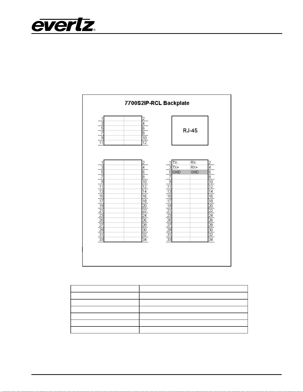
Figure 3-3: RS-422 Pins...................................................................................................................................5
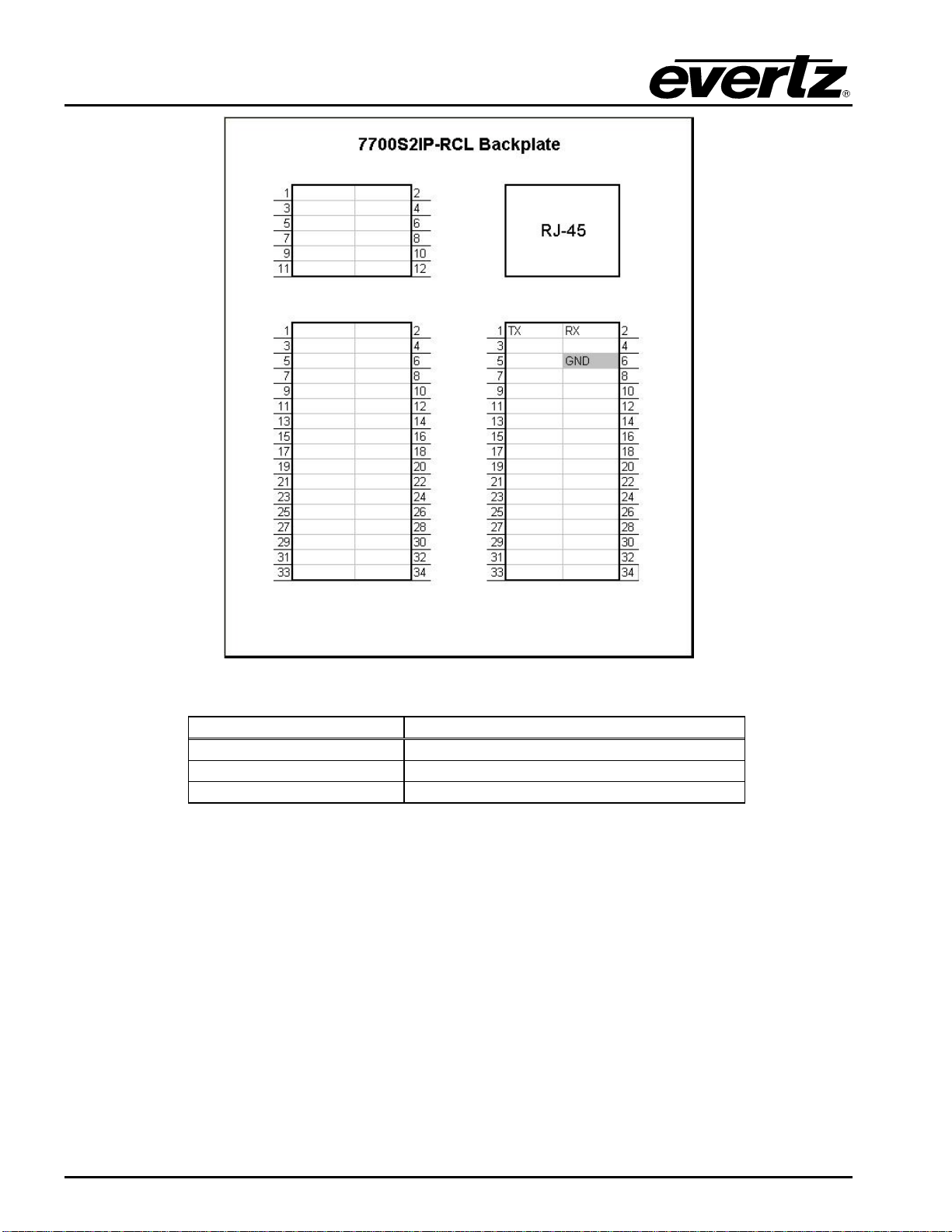
Figure 3-4: RS-232 Pins...................................................................................................................................6
Figure 3-5: Upgrade Jumper ............................................................................................................................7
Figure 3-6: ‘Connect To’ Window.....................................................................................................................7
Figure 3-7: COM1 Properties ...........................................................................................................................8
Figure 3-8: HyperTerminal Main Menu.............................................................................................................9
Figure 3-9: 7700S2IP-RCL Network Configuration Menu................................................................................9
Figure 3-10: 7700S2IP-RCL Trap Destinations..............................................................................................11
Figure 3-11: VLPro Hardware Navigation Tree..............................................................................................12
Figure 3-12: Specifying NTP Server...............................................................................................................13
Figure 3-13: Checking NTP Server Communication......................................................................................14
Figure 3-14: Controller Interface Parameters.................................................................................................15
Figure 3-15: Session Configuration Update Indication...................................................................................17
Figure 3-16: Conducting a Session Configuration Update.............................................................................18
Figure 3-17: Checking System Controller Communication ............................................................................19
Figure 3-18: QMC-2 Interface Parameters.....................................................................................................20
Figure 3-19: Router Destination to QMC-2 Input............................................................................................21
Figure 3-20: Using Destination Combo Box...................................................................................................22
Figure 3-21: Specifying a Destination Alias....................................................................................................23
Figure 3-22: All QMC-2 Inputs Specified........................................................................................................24
Figure 3-23: Selecting Controller Inputs.........................................................................................................25
Figure 3-24: Checking QMC-2 Configuration Up-To-Date Status..................................................................26
Tables
Table 3-1: RS-422 Wiring.................................................................................................................................5
Table 3-2: RS-232 Wiring.................................................................................................................................6

7700 MultiFrame Manual
7700S2IP-RCL QMC-2 To RCL Translator
Revision 2.0
REVISION HISTORY
REVISION DESCRIPTION DATE
1.0 First Release Feb 08
2.0 Add Source and Destination Aliases. General clean up. Feb 09
Information contained in this manual is believed to be accurate and reliable. However, Evertz assumes no responsibility for the use thereof nor
for the rights of third parties, which may be affected in any way by the use thereof. Any representations in this document concerning
performance of Evertz products are for informational use only and are not warranties of future performance, either expressed or implied. The
only warranty offered by Evertz in relation to this product is the Evertz standard limited warranty, stated in the sales contract or order
confirmation form.
Although every attempt has been made to accurately describe the features, installation and operation of this product in this manual, no
warranty is granted nor liability assumed in relation to any errors or omissions unless specifically undertaken in the Evertz sales contract or
order confirmation. Information contained in this manual is periodically updated and changes will be incorporated into subsequent editions. If
you encounter an error, please notify Evertz Customer Service department. Evertz reserves the right, without notice or liability, to make
changes in equipment design or specifications.

7700 MultiFrame Manual
7700S2IP-RCL QMC-2 To RCL Translator
Revision 2.0
This page left intentionally blank

7700 MultiFrame Manual
7700S2IP-RCL QMC-2 To RCL Translator
Revision 2.0
Page-1
1. OVERVIEW
The basic function of the 7700S2IP-RCL is to provide an interface between a QMC-2 and a RCL-based
router system. In essence, the 7700S2IP-RCL makes the RCL router system (maximum supported
size is 1024 sources by 1024 destinations) appear as a Quartz router (maximum size 240 sources by
16 destinations) to the QMC-2. The 7700S2IP-RCL can communicate with up to two controllers (a
primary and a secondary). Each controller may have either 1 or 2 system controller cards installed.
Thus, the 7700S2IP-RCL can communicate simultaneously with up to 4 system controller cards.

7700 MultiFrame Manual
7700S2IP-RCL QMC-2 To RCL Translator
Page-2
Revision 2.0
2. CARD EDGE CONTROLS
2.1. DETERMINING CURRENT IP ADDRESS SETTINGS
To read the current IP address during normal operation, press the front switch DOWN. The IP address
can be read on the four-character alphanumeric display.
2.2. RESTORING FACTORY DEFAULTS
To restore all settings to factory defaults, apply power to the card while holding the toggle switch UP
until the green LED is illuminated.
2.3. CARD EDGE LEDS
LED 22 is illuminated when Ethernet activity is detected.
All other card edge LEDs are for factory use only.
Figure 2-1: Card Edge

7700 MultiFrame Manual
7700S2IP-RCL QMC-2 To RCL Translator
Revision 2.0
Page-3
3. CONFIGURATION
3.1. EXAMPLE CONFIGURATION
The setup of Figure 3-1 will be used to demonstrate how to configure the 7700S2IP-RCL.
Figure 3-1: Example Setup
Figure 3-1 contains the following elements:
•A primary RCL router controller with a system controller installed in slot 1. The system
controller has IP address 192.168.18.39. It controls the primary RCL router. The primary RCL
router has destination names Out1P, Out3P, Out5P, Out7P, and Out9P and source names
In1P, In3P, In5P, In7P, In9P, In11P, In13P, In15P within area name area.

7700 MultiFrame Manual
7700S2IP-RCL QMC-2 To RCL Translator
Page-4
Revision 2.0
•A secondary RCL router controller with a system controller installed in slot 1. The system
controller has IP address 192.168.18.40. It controls the secondary RCL router. The secondary
RCL router has destination names Out1S, Out3S, Out5S, Out7S, and Out9S and source names
In1S, In3S, In5S, In7S, In9S, In11S, In13S, In15S within area name lala.
•RCL router destinations Out1, Out3, Out5, Out7, and Out9 are connected to QMC master
control switcher inputs Program, Preset, Keyer 1 Fill, Keyer 1 Key, DVE Background
respectively.
•An NTP server with IP address 192.168.18.37. The time provided by the NTP server is used by
the 7700S2IP-RCL when adding entries to its event log.
•VistaLINK PRO with IP address 192.168.18.38. VLPro will be used to configure the 7700S2IP-
RCL. VLPro will receive SNMP traps from the 7700S2IP-RCL.
•7700S2IP-RCL with IP address 192.168.18.54.
The 7700S2IP-RCL communicates:
•with VLPro using SNMP
•with the RCL system controllers via the RCL protocol over a TCP link
•with the QMC master control switcher using the Quartz Remote Control Protocol over a serial
link
Conceptually, this is equivalent to:
Figure 3-2: Example Setup

7700 MultiFrame Manual
7700S2IP-RCL QMC-2 To RCL Translator
Revision 2.0
Page-5
3.2. STEP 1: CONNECT 7700S2IP-RCL TO THE QMC MASTER CONTROL SWITCHER
1. Ensure there is no power applied to the 7700S2IP-RCL.
2. If using RS-422, connect the pins of the 7700S2IP-RCL to those of a serial port of the QMC
master control switcher according to Figure 3-3 and Table 3-1.
3. If using RS-232, connect the pins of the 7700S2IP-RCL to those of a serial port of the QMC
master control switcher according to Figure 3-4 and Table 3-2.
4. Apply power to the 7700S2IP-RCL.
Figure 3-3: RS-422 Pins
7700S2IP-RCL Pin Name QMC Master Control Switcher Pin Name
TX- RX-
TX+ RX+
GND RX GND
RX- TX-
RX+ TX+
GND TX GND
Table 3-1: RS-422 Wiring

7700 MultiFrame Manual
7700S2IP-RCL QMC-2 To RCL Translator
Page-6
Revision 2.0
Figure 3-4: RS-232 Pins
7700S2IP-RCL Pin Name QMC Master Control Switcher Pin Name
TX RX
RX TX
GND GND
Table 3-2: RS-232 Wiring

7700 MultiFrame Manual
7700S2IP-RCL QMC-2 To RCL Translator
Revision 2.0
Page-7
3.3. STEP 2: CONNECT A PC TO THE DEBUG/MONITOR PORT
The network and SNMP parameters of the 7700S2IP-RCL must be configured via its debug/monitor
port, the header of which is labelled J1. A special Evertz adapter cable allows this port to connect to the
COM port of a personal computer. The following steps describe this procedure.
1. Locate the small, keyed, four–pin end of the upgrade cable provided by Evertz.
2. Connect it to the four-pin interface (J1) near the front of the 7700S2IP-RCL, directly above the
card unlock latch.
Figure 3-5: Upgrade Jumper
3. Connect the other end of the upgrade cable to a straight-through serial cable. Connect the
serial cable to the serial or COM port of the computer.
4. Initiate HyperTerminal on your computer by selecting:
“Start\Programs\Accessories\Communications\HyperTerminal”.
5. Enter a name for your connection, for example: 7700S2IP-RCL.
6. Press the <Enter> key. A new “Connect To” window will appear.
Figure 3-6: ‘Connect To’ Window

7700 MultiFrame Manual
7700S2IP-RCL QMC-2 To RCL Translator
Page-8
Revision 2.0
7. In the “Connect using” region, select COM1 from the drop down menu. If COM1 is in use,
select an alternate COM port.
8. Press the <Enter> key or select OK. This opens the “COM Properties” window.
Figure 3-7: COM1 Properties
9. Enter the information for the COM1 Properties settings as listed in the screen above.
10. Press the <Enter> key or select OK. The “COM Properties” window closes, leaving the
HyperTerminal window open.
11. Apply power if the 7700S2IP-RCL does not have power. The boot sequence and Main Menu
are displayed in the HyperTerminal window.
12. If the 7700S2IP-RCL has power, press the <Enter> key to view the 7700S2IP-RCL’s menu
system.
13. Various 7700S2IP-RCL parameters are configurable via the 7700S2IP-RCL’s menu system, the
root of which is called Main Menu.

7700 MultiFrame Manual
7700S2IP-RCL QMC-2 To RCL Translator
Revision 2.0
Page-9
Figure 3-8: HyperTerminal Main Menu
3.4. STEP 3: CONFIGURE NETWORK PARAMETERS
Figure 3-9: 7700S2IP-RCL Network Configuration Menu
The network parameters of the 7700S2IP-RCL can only be configured by using its menu system.

7700 MultiFrame Manual
7700S2IP-RCL QMC-2 To RCL Translator
Page-10
Revision 2.0
1. From the Main Menu select Network Configuration.
2. Select Set IP Address then enter the IP address, 192.168.18.54, of the 770S2IP-RCL.
3. Select Set Netmask then enter the subnet mask, 255.255.255.0, of the 7700S2IP-RCL.
4. Select Set Gateway to set the gateway IP address if the 7700S2IP-RCL resides on an IP
network which differs from that of the controller(s), NTP server, or VLPro. The gateway can be
left as 0.0.0.0 if the 7700S2IP-RCL and the controller(s), NTP server and VLPro reside on the
same IP network.
5. For a manually entered network configuration, ensure DHCP enabled is set to False. A setting
of True means the 7700S2IP-RCL will, upon boot, try to fetch network settings from a DHCP
server. The Use DHCP entry permits changes to this parameter.
6. Once the network settings are configured, select Save and Exit before exiting the Network
Configuration to save the settings, otherwise select Exit.
7. Reboot the 7700S2IP-RCL. This can be done by selecting Engineering/Debug from the Main
Menu, then Reboot, then y.
8. Ensure the VLPro machine can ping the 7700S2IP-RCL.
"
The 7700S2IP-RCL must be rebooted for any network setting changes to take
effect.

7700 MultiFrame Manual
7700S2IP-RCL QMC-2 To RCL Translator
Revision 2.0
Page-11
3.5. STEP 4: CONFIGURE SNMP TRAP DESTINATIONS
Figure 3-10: 7700S2IP-RCL Trap Destinations
The SNMP parameters, including the SNMP trap destinations, of the 7700S2IP-RCL can only be
configured by using its menu system.
1. From the Main Menu select SNMP Setup.
2. Select Trap Setup.
3. Select Set Trap IP Address.
4. Enter the IP address of the host to receive SNMP traps. For our example this is 192.168.18.38.
5. Select Save and Exit to save the settings, otherwise select Exit.
6. The menu system of the 7700S2IP-RCL is no longer required. As such, the adapter cable can
be removed from the debug/monitor port.

7700 MultiFrame Manual
7700S2IP-RCL QMC-2 To RCL Translator
Page-12
Revision 2.0
3.6. STEP 5: OPEN 7700S2IP-RCL VLPRO CONFIGURATION VIEW
Figure 3-11: VLPro Hardware Navigation Tree
1. Launch VLPro. The IP address of the 7700S2IP-RCL, 192.168.18.54, should appear in the
hardware navigation tree.
2. Right click on the IP address.
3. Click View Configuration.

7700 MultiFrame Manual
7700S2IP-RCL QMC-2 To RCL Translator
Revision 2.0
Page-13
3.7. STEP 6: CONFIGURE NTP SERVER IP ADDRESS (OPTIONAL)
Figure 3-12: Specifying NTP Server
The 7700S2IP-RCL maintains an event log. It is located on the General tab as shown in Figure 3-12.
Each entry in the event log has a timestamp. If the 7700S2IP-RCL is not communicating with an NTP
server, it will use the system up time in relation to January 1, 2008 for its event log timestamps. If the
7700S2IP-RCL is communicating with an NTP server, it will retrieve the UTC time from the server,
calculate the local time using the Local Offset settings, and use the local time for its event log
timestamps. To set the IP address of the NTP server:
1. From the VLPro configuration view, click the General tab.
2. Enter the IP address of the NTP server. For our example, this corresponds to 192.168.18.37.
3. Click the icon to the right of Apply.
4. Click the icon to the right of Refresh.

7700 MultiFrame Manual
7700S2IP-RCL QMC-2 To RCL Translator
Page-14
Revision 2.0
Figure 3-13: Checking NTP Server Communication
5. Notice how the number associated with Packets Received has become non-zero. This
indicates the 7700S2IP-RCL is communicating with the NTP server.
6. The NTP server returns UTC time. To obtain the local time, set a local offset using the +/-, hh,
mm, and ss local offset parameters. Be sure to follow by clicking the icon to the right of Apply.

7700 MultiFrame Manual
7700S2IP-RCL QMC-2 To RCL Translator
Revision 2.0
Page-15
3.8. STEP 7: CONFIGURE CONTROLLER INTERFACE PARAMETERS
Figure 3-14: Controller Interface Parameters
1. From the VLPro configuration view, click the Controller Interface tab.
2. Enter the area name of the primary controller. As per our example, the area name of the
primary controller is area. The area name is case sensitive.
3. Enter the area name of the secondary controller. As per our example, the area name of the
secondary controller is lala. The area name is case sensitive.
4. Optionally, enter the name of the video level used by the primary controller. The level name is
case sensitive. If no level is specified then the 7700S2IP-RCL will indicate all levels when
issuing the crosspoint switch request.

7700 MultiFrame Manual
7700S2IP-RCL QMC-2 To RCL Translator
Page-16
Revision 2.0
5. Optionally, enter the name of the video level used by the secondary controller. The level name
is case sensitive. If no level is specified then the 7700S2IP-RCL will indicate all levels when
issuing the crosspoint switch request.
6. Enter the IP address of the primary system controller in slot 1. As per our example, this is
192.168.18.39.
7. Enter the IP address of the secondary system controller in slot 1. As per our example, this is
192.168.18.40.
8. By default, the system controllers listen on TCP port 12345 for incoming connection requests. If
this value has been modified, then the appropriate TCP port needs to be specified for the
system controllers.
9. Click the icon to the right of Apply.
10. Click the icon to the right of Refresh.
Other manuals for 7700 Series
127
This manual suits for next models
1
Table of contents
Other evertz Electronic Dictionary manuals

evertz
evertz 7700 Series User manual

evertz
evertz 7700 Series User manual

evertz
evertz 7700 Series User manual

evertz
evertz 570NAT-HW-X19 User manual

evertz
evertz 7700 Series User manual

evertz
evertz MultiFrame EMX3 User manual

evertz
evertz 7700 Series User manual

evertz
evertz 7880IPG-NAT Series User manual

evertz
evertz 7700 Series User manual