Chell CCD100 User manual

Please read this manual carefully before usingthe instrument.
Use of this equipment in a manner notspecified in this
manual may impair the user’s protection.
Chell Document No. : 900219 Issue 1.0
ECO: ----Date: 20th February 2018
Chell’s policy of continuously updating and improving productsmeans that thismanual may contain
minor differences in specification, components and circuit design from the actual instrument supplied.

INDEX
SECTION 1 - INSTRUMENT OVERVIEW ........................................................................................ 2
SECTION 2 - SPECIFICATION....................................................................................................... 3
2.1 POWER SUPPLY:...........................................................................................................................3
2.2 OPERATING CONDITIONS:..............................................................................................................3
2.3 MEASUREMENT AND OUTPUTS:.....................................................................................................3
SECTION 3 - INSTALLATION AND INTERCONNECTIONS........................................................... 4
3.1 TRANSDUCER SOCKET PINOUT -15 WAY 'D' TYPE ..........................................................................4
3.2 INTERFACE SOCKET PINOUT –MINIATURE 15 WAY 'D' TYPE ............................................................4
3.3 USB CONNECTOR –USB TYPE-C.................................................................................................5
3.4 POWER CONNECTION SOCKET ......................................................................................................5
3.5 PANEL MOUNTING ........................................................................................................................5
SECTION 4 - FRONT PANEL OPERATION.................................................................................... 6
4.1 INTRODUCTION .............................................................................................................................6
4.2 COMMON SWITCH FUNCTIONS ......................................................................................................6
(a) Menu screens........................................................................................................................6
(b) Editable screens.....................................................................................................................6
(c) Edit mode ...............................................................................................................................6
4.3 HMI BREAKDOWN .........................................................................................................................7
(a) Main Screen (not changing Setpoint)....................................................................................7
(b) Main Screen (changing Setpoint)..........................................................................................7
(c) Main Screen (Setpoint Valve Control)....................................................................................8
(d) Main Menu Screen.................................................................................................................9
(e) Setpoint Screen (Excitation Screen if millivolt option fitted) ..................................................9
(f) Input Screen.........................................................................................................................10
(g) Comms Screen....................................................................................................................11
(h) Filtering Screen ....................................................................................................................11
(i) Relay Screen ........................................................................................................................12
(j) Factory Defaults Confirmation Screen.................................................................................12
SECTION 5 - WEBSERVER........................................................................................................... 13
5.1 MAIN PAGE.................................................................................................................................13
5.2 LIVE DATA...................................................................................................................................13
5.3 CHANNEL CONFIGURATION PAGE ................................................................................................14
5.4 CONTROL CONFIGURATIONPAGE ................................................................................................14
(a) Communication....................................................................................................................15
(b) Relays...................................................................................................................................15
(c) Filtering.................................................................................................................................15
SECTION 6 - SERIAL & TCP COMMUNICATION........................................................................ 16
6.1 INTRODUCTION ...........................................................................................................................16
6.2 COMMAND/QUERY FORMAT.........................................................................................................16
6.3 MAIN COMMANDS .......................................................................................................................17
(a) Output current readings – ‘r’ ................................................................................................17
(b) Output current readings repeatedly – ‘rp’............................................................................18
(c) Setpoint value – ‘spv’ ...........................................................................................................18
(d) Setpoint mode – ‘spm’ .........................................................................................................18
(e) Setpoint source – ‘sps’.........................................................................................................19
(f) Setpoint initial value – ‘siv’ ...................................................................................................19
(g) Setpoint initial mode – ‘sim’ .................................................................................................19

6.4 COMMS COMMANDS ...................................................................................................................20
(a) Ethernet IP address – ‘eip’ ...................................................................................................20
(b) Ethernet subnet mask – ‘esm’ ..............................................................................................20
6.5 CHANNEL SETUP COMMANDS......................................................................................................21
(a) Input channel units string – ‘uiu’..........................................................................................21
(b) Input channel range – ‘uir’ ...................................................................................................21
(c) Input channel full scale –‘uif’...............................................................................................21
6.6 FILTERING COMMANDS................................................................................................................22
(a) Filter band – ‘flb’...................................................................................................................22
(b) Filter size – ‘fls’.....................................................................................................................22
6.7 RELAY CONTROL COMMANDS ......................................................................................................22
(a) Relay trip point – ‘rlt’.............................................................................................................22
(b) Relay hysteresis – ‘rlh’..........................................................................................................23
6.8 OTHER COMMANDS.....................................................................................................................23
(a) User input rezero – ‘irz’........................................................................................................23
(b) Date of last factory calibration – ‘dlc?’.................................................................................23
(c) Retrieve all settings – ‘ras’ ...................................................................................................23
SECTION 7 - PRINCIPLES............................................................................................................ 24
7.1 INTRODUCTION ...........................................................................................................................24
7.2 ANALOGUE INPUTS .....................................................................................................................24
(a) Range ...................................................................................................................................24
(b) Full Scale Voltage.................................................................................................................24
(c) Units String ...........................................................................................................................24
7.3 ANALOGUE OUTPUTS..................................................................................................................24
7.4 SETPOINT CONTROL ...................................................................................................................25
(a) Setpoint Mode......................................................................................................................25
(b) Setpoint Source....................................................................................................................25
7.5 USER REZERO ............................................................................................................................25
7.6 ADAPTIVE FILTERING...................................................................................................................26
(a) Operational band.................................................................................................................26
(b) Filter size ..............................................................................................................................26
SECTION 8 - SERVICE AND CALIBRATION................................................................................ 27
8.1 SERVICE.....................................................................................................................................27
8.2 CALIBRATION..............................................................................................................................27
8.3 ADJUSTMENT..............................................................................................................................27
8.4 CLEANING ..................................................................................................................................27
8.5 END OF LIFE...............................................................................................................................27
SECTION 9 - APPENDICES .......................................................................................................... 28
9.1 APPENDIX A...............................................................................................................................28
9.2 APPENDIX B...............................................................................................................................29
9.3 APPENDIX C...............................................................................................................................30
TABLES
Table1 – CCD100 Command Set Summary.................................................................... 28
Table2 – FactoryDefaults................................................................................................ 29
Table3 – Settings in ‘ras’ command string..................................................................... 30

Page 2
Section 1 - Instrument Overview
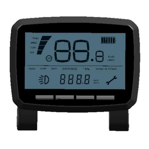
The CCD100 is amulti featured process display controller, capable of interfacing directly to
amass flowmeter or other process transducers. This is thethird generation of the Chell
CCD100 display.
The CCD100 is asingle channel unit which can be used to operate aflow controller or
display the output from apressure transducer. It supports both voltage transducers
(typically 5&10Vfull scale) and also millivolttransducers (max 250mV full scale). Thereis
also asecondary channel which can be used for external command (setpoint) control
(+10v full scale). TheCCD100 also hasthe ability to power such devices with either ±15dc
@ 250mA or +24vdc@ 300mA.
Interfaces to the CCD100 include RS232 (via USB), Ethernet or itcan be used with just
analogue signals.
Note: This manual has been written for firmware version 1.00.

Page 3
Section 2 - Specification
2.1 Power Supply:
Line voltage:
24V DC. ±5%
Consumption:
less than
500mA
Protection:
Internal resettable fuse
2.2 Operating conditions:
Operating temperaturerange:
+5°C to +50°C (40°F to 122°F)
Storage temperature range:
-20°C to +70°C (-40°F to 158°F)
Maximum Relative hum
idity:
95% at 50°C (non condensing)
Warm uptime tofull accuracy:
15 minutes (assumesunit already stabilised at
ambient andexcludes transducer warm up time).
2.3 Measurement and Outputs:
Power supply out:
±15V dc@ 250mA max.
+24V dc@ 300mA max
.
Use ±15V or +24V transducer excitation.
Do Not Use Both.
DC input signal:
0
-
10.0V dc
(guaranteed limit is +11.7V)
Input impedance:
>5
0
0 kOhm
DC output:
Retransmission of Input.
Limits of ±10.8V dc, into10 kOhm or greater.
Output accuracy (afterzero):
±0.1% of reading ±0.01% full scale
Setpoint (Command) Output:
Configurable 0
-
10
Vdc.
Close = <-0.25 V
Open = >7.0 V(@5V FS) or >12.0V (@10V FS)

Page 4
Section 3 - Installation and Interconnections
The instrument is designed to be panel mounted, and is astandard96x48mm panel meter
enclosure. Note that the instrument must always be situated insuch away as toenable
adequate air circulation about the unit.
If a transducer wassupplied withthe CCD100 a suitable cable mayhave been included.
3.1 Transducer socket Pinout - 15 Way 'D' Type
Pin Number
Designation
2
Signal
5
Power Gnd
6
-
15V Supply
7
+15V Supply
8
Command Output (V
)
or Excitation
(mV option)
11
Signal Return
12
Signal Return
13
+24V Supply
15
Earth/Chassis
All other pins
Not Connected
If the transduceris being powered from another source (e.g. amains powered supply) it
will only be necessary to connectto the twosignal pins.
Note: The CCD100 has afully floating differential input.For single ended use (i.e.
tranducers withdifferential output) join0V (pin5) & Signal Return (pin12) at the transducer.
Ensure the common mode inputrange is not exceeded.
3.2 Interface Socket Pinout – Miniature 15 Way 'D' Type
Pin Number
Designation
1
Analogue Output
2
Relay 2 Com
3
Relay 2 NO
4
Relay 2 NC
5
0V (Signal Ground)
6
External Setpoint Return
7
N/C
8
External Setpoint
9
N/C
10
0V (Signal Ground)
11
TTL Inpu
t
–
Disable Menu
12
TTL Input
–
Disable Zero
13
Relay 1 Com
14
Relay 1 NO
15
Relay 1 NC

Page 5
3.3 USB Connector – USB Type-C
The connector supports USB-C 2.0cables without the SuperSpeed pairs.Therefore
connecting afully featured USB-C 3.1 cable willnot provide SuperSpeed functionality,
although the cable will still work as per the USB 2.0 specification.
USB is provided for legacy serial data comms and debugging purposes.
3.4 Power Connection Socket
The panel meter display requires a24V, 500mA supplyto operate. This must bearectified
and regulated directcurrent supply, capable of 15W(recommended). Although the
CCD100 has an internal fuse and power supply overload shut-downprotection the supply
to the CCD100 should be protected by fuse or other suitable electronic method.
A standard5mm diameter ‘dc power jack’ is required toconnectto the CCD100.
Connect the positive conductor to the centrepin. Connect the negative (0V) conductor to
the outer of the jack.
If requested, acompatible AC-DC switch mode power supply willhave been supplied with
the unit.
Cautions:
Ensure correct power supply rating and polarity.
Do not use a partially assembled or faulty unit.
Incorrect use of this equipment, or use in a manner not specified may
impair the users protection.
3.5 Panel Mounting
A panel mount kit will have been supplied with the instrument. This consists of:
2 M3x6 screws. 2 brackets. 2 50mm screws.
Fit the M3x6 screws into the side of the unit into the diagonally opposed holes. Do not
tighten these screws, to allow the bracket toslide over the screw head. Thread locking
adhesive may be used but is notrequiredasthese screws cannot rotate once the bracket
is tightened.
Insert the meter into the panel. A hole cut-outof 92 x45mm is recommended.
Slip the mounting bracket over the screwhead andtighten the 50mm screw.
The unit should now be secure.

Page 6
Section 4 - Front Panel Operation
4.1 Introduction
The front panel consists of a128x32 pixel monochrome graphicOLED display with 6
membrane key switches below it. Eachswitch has legends on and above or below it to
indicate its function under different conditions, although thereare certain common
functions toeach screen, as detailedbelow.
For the purpose of the following sub-sections, the switchesshallbe referred to using the
legends on the buttons.
4.2 Common Switch Functions
The switches on certain types of screens and in certain modes, havethe same functionality
as detailed here:
(a) Menu screens
On the menu screen, the ‘ ’&‘▼’switches are used to navigate through the menu
options. The ‘Func’switch is used to go back to the main screen.The ‘Zero’switch
doubles up as an Enter switch and this actions the chosenmenuselection. This
may be to go to asub-menu or to an editable or information screen (see HMI
breakdown for more details).
(b) Editable screens
On any screen that has editable fields,switches ‘ ’&‘▼’move the selection
between the possibleeditable fields. ‘Func’goes back to the parent screen which is
usually themenuthat was used to get to the screen in question. ‘Zero’activates edit
mode (see below).
(c) Edit mode
When in edit mode, theedit cursor appears on the first character in the editable field
(the cursor is ahorizontal bar below the character being edited). If the field is bigger
than 1character then switches ‘◄’&‘►’areused to moveleft andright across the
field. Ifthe fieldis only one character (e.g.aYes/Noselection) or has arolling
selection (e.g. for selection of apercentage) then ‘◄’&‘►’do nothing. Switches
‘’&‘▼’are used to change the character being edited within thevalid range (field
position dependant). ‘Func’cancels edit mode and returns the field to it’s previous
value. ‘Zero’accepts any changes to the fieldand also comes out of edit mode.

Page 7
4.3 HMI breakdown
Here follows a complete breakdown of all CCD100 screens:
(a) Main Screen (not changing Setpoint)
The main screen shows the main channelinput data(with range, full-scale and
calibration applied) and the associatedunitsstring. If aninput is over range (more
than 15% above full scale voltage) then the data value is replaced with the over
range error –“RANGE”. This screen also shows the current mode of the setpoint, if
not in AUTO (i.e. OPEN or CLOSE). If eitherof the relays have been tripped then
they are also indicatedas such on the farright of the screen.
Switch Functions:
Func
No function *
Go toMain Menu screen
►
Enable setpoint mode override, active for2 seconds
►
(override mode)
Change setpoint mode to AUTO
▲
Change setpoint value (main screen changes as below)
▲
(override mode)
Change setpoint mode to OPEN
▼
Change setpoint value
(main screen changes as below)
▼
(override mode)
Change setpoint mode to CLOSE
Zero
Perform inputrezero (if held for 3 seconds)
*By default theFunc switch does nothing, butspecial builds ofthe CCD100 may includefunctionality for this
switch. In such cases an addendum to this manual will indicate the function.
(b) Main Screen (changingSetpoint)
When performing alivesetpoint change, the main screenis aspreviously, but with
the addition of the current setpoint value (initiated viaan initial press of the ‘ ’or
‘▼’switches). Note that the setpoint valueis not permanent –ifthe ‘ ’or‘▼’
switches are not pressed at all for 3seconds,then the setpoint value disappears.

Page 8
Special note for millivolt option:
If themillivolt optionis fitted, then thecommandoutput isused astheexcitation source for the
transducer. Assuch theSP: will changetoEXP: toindicatethattheuser iscontrollingtheexcitation
output.
Switch Functions:
Func
No function *
(see (a) above)
Go toMain Menu screen
►
Enable setpoi
nt mode override, active for
3
seconds
►
(override mode)
Change setpoint mode to AUTO
▲
Change setpoint value (hold forcontinuous change)
▲
(override mode)
Change setpoint mode to OPEN
▼
Change setpoint value (hold forcontinuous change)
▼
(override
mode)
Change setpoint mode to CLOSE
Zero
Perform inputrezero (if held for 3 seconds)
(c) Main Screen (Setpoint Valve Control)
Rather than commanding the setpoint to aspecificvalue, the setpoint mode can be
changed to Open orClosed which overrides any previously setvalue. Again the
main screen showseverything asnormal, but with the addition of the OPEN or
CLOSE identifier ifthis mode has been set. Byputting the device intooverride mode
it is possible to force the setpoint to be Open or Closed. This is done by pressing
the override switch thenthe appropriate mode switch. Either mode can be cancelled
by switching back toAuto mode (by effectively pressing the override switch twice).
Switch Functions:
Func
No function *
(see (a) above)
Go toMain
Menu screen
►
Enable setp
oint mode override, active for3
seconds
►
(override mode)
Change setpoint mode to AUTO
▲
Change setpoint value (hold forcontinuous change)
▲
(override mode)
Change setpoint mode to OPEN
▼
Change setpoint value (hold forcon
tinuous change)
▼
(override mode)
Change setpoint mode to CLOSE
Zero
Perform inputrezero (if held for 3 seconds)

Page 9
(d) Main Menu Screen
The Main Menuscreen allowstheuser toselect screensthat are used for the
configurationof the CCD100 –the setpoint (initial value, initial mode, source), input
(range, full scale, unitsstring), comms, filtering and relays can all be configured
from screens selected via the main menu. It isalsopossible toresetsettingsto their
factory defaults from the Main Menu screen.Only 4options can be shown on the
screen at any one time, so the menu list scrolls up until the last itemis shown, and
then the selection arrows move down to allow for selection of any menu item.
Special note for millivolt option:
If the millivolt option is fitted, thentheSetpoint menu option will be listedas Excitationto allowfor
configuration of the initial excitation value only.
Switch Functions:
Func
Go back toMainscreen
No function
►
No function
▲
Go toprevious menu selectio
n
▼
Go tonext menu selection
Zero
Go toscreen associated with menu selection
(e) Setpoint Screen (Excitation Screen if millivolt option fitted)
From the setpoint screen youcan edit the value of the command setpoint as wellas
change the mode (AUTO, OPEN, CLOSED) and the source (INTERNAL, SLAVE). If
SLAVE is selected then the percentage sign(%) appears next to the SP value. For
more information on the command setpoint,see the Principles section - 7.4.

Page 10
Special note for millivolt option:
If the millivolt option is fitted, the only configurable item here is the initial excitation value.
Switch Functions:
Func
Go back toMainMenu screen
Select previous character when in edit mode
►
Select next character when in edit mode
▲
Move edit field selection up
▼
Move edit field selection down
Zero
Go toedit mode forcurrently selected field
(f) Input Screen
This screen allows youto change the inputchannel range and full-scale voltage
(see thePrinciples section (7.2) for more information on this) and also assign aunits
label (up to 5characters) for the channel data.The number of decimal places
selected on the range field dictates the number of decimal places shownfor the
input channel data onthe Main screen. To reduce the number of decimal places,
change the number under the edit cursor toadecimal point andthe system will
auto format the field when ‘Zero’ is pressed.
Special note for millivolt option:
If the millivolt option is fitted, the full scale is represented in mV and shown as such on the screen.
Switch Functions:
Func
Go back toMainMenu screen
Select previous character when
in edit mode
►
Select next character when in edit mode
▲
Move edit field selection up
▼
Move edit field selection down
Zero
Go toedit mo
de forcurrently selected field

Page 11
(g) Comms Screen
The IP address and the subnet mask of the device canbe changed here. The device
will need to be reset toenact these changes.
Switch Functions:
Func
Go back toComms Menu screen
Go toprevious menu selection
►
Go tonext menu selection
▲
No function
▼
No function
Zero
Go toscreen associated with menu select
ion
(h) Filtering Screen
This screen allows the user to modify the band and buffer size of the adaptive filter.
The filter only appliesto the display and comms output readings. The band is
represented as apercentage of FS and can be set between 0.00% (OFF) and 1.00%
and also to ON. The buffer size allows settings between0and 6seconds of filtering.
For more information on the adaptive filter, see the Principles section (7.6)
Switch Functions:
Func
Go back toMainMenu screen
Select previous character when in edit mode
►
Select next character when in edit mode
▲
Move edit field selection up
▼
Move edit field selection down
Zero
Go toedit mode forcurrently selected field

Page 12
(i) Relay Screen
This screen allows you to set thetrip point for when the relays switch. The relays
also contains some hysteresisto stop them ‘chattering’. This is configurable from
this screen aswelland is represented as apercentage of full scale of the input
channel, with limits of 0.0% (i.e. no hysteresis) to 10.0%.
Switch Functions:
Func
Go back toMainMenu screen
Select previous character when in edit mode
►
Select next character when in edit mode
▲
Move edit field selection up
▼
Move edit field selection down
Zero
Go toedit mode forcurrently selected field
(j) Factory Defaults Confirmation Screen
If Factory Defaults is selected from the MainMenu, this screen appears to ask for
confirmation of the requested function. If confirmed then the screen changesto
show apercentage of completion of the factory defaults and oncecompleted the
CCD100 will restart.
Switch Functions:
Func
Go back toMainMenu screen
If held, starts factory default when Zero is pressed
►
No function
▲
No function
▼
No function
Zero
Starts factory default if
is held as well
.

Page 13
Section 5 - Webserver
5.1 Main page
The Web server can be used by entering the IP address of thedevice intoabrowser
address bar. This allows the user control ofvarious settings within the device,andtoread
the devices currentreading.
Along the top are aseries of tabs to allow the user to switch to various sections of device
control. Also along the side is the device serial number andcontrols to start streaming
communications,note for TCP streaming to work a TCPconnection on port101 must be
pre-established (the unit does not datastream over the HTTPport(80)).
5.2 Live data
The live datapage is the first page the user will see when the web server is loaded up. The
main feature of this page is the live data output from the device,butit also has the
capabilities torezero the channel, to change the setpoint value and to set the setpoint
valve postion.
Note: The setpoint is set in engineering units as configuredby the range setting and
cannot be set to more than this range configuration.
The units string and device range canbe changed from the Channel cfg page.

Page 14
5.3 Channel Configuration page
The channel configuration contains channel setup options.
·Units string allows the userto change the units of thechannel.
·Range is the Engineering unit conversion of the Voltage output from the transducer (e.g. in the image
above 10 Volts = 100 mbar).
·The number of decimal places set for the range dictates its display precision
·Fullscale is the maximum Voltage output of the transducer.
·Source is where the setpoint is referenced from, Internal will output the number entered as the setpoint
value and Slave will outputa percentage of the external input.
·Init value is the value to which the setpoint will be set to at start-up.
·Init mode is the valve position, auto is the normal setpoint mode, Open will set maximum range voltage
output and closed sets minimum range
5.4 Control Configuration page
The control configuration page is made up of multiple sections each controlling adifferent
section of the device.

Page 15
(a) Communication
The communicationpage allows the user to change the IP address and Subnet mask of
the device.
Obviously no octetin the IP Address or Subnet mask can beset to higher than ‘255’.
Once applied the device will need to reset, so the communications page will show a pop-
up (see below) that prompts the user to refresh.
(b) Relays
The Relays page allows the user to change the controls forthe twoonboard relays.
·The hysteresis is a window around the trip point at which the relays will trigger, soto trigger the relay in
the image above the input must get to Trip point + 2% (of fullscale) and the relay will not switch off until
the input drops to Trip point – 2% (of fullscale).
·The trip point is the Engineering unit at which the Relay will trip
(c) Filtering
Filtering is used to reduce noise in the device.
·Band relates to the filteringlimits. The setting is percentage of fullscale and can be set between 0.01%
and 1.00%. Other settings are On so that the filtering will be fully active, filtering all data all the time, and
Off where there is no filtering.
·The size is the time the data is filtered over, a time greater than 5 will turn the filtering band to on
automatically.
For more information on how the adaptive filter works, see the Principles section (7.6).

Page 16
Section 6 - Serial & TCP Communication
6.1 Introduction
The CCD100 allows full control and feedbackvia TCP/IP and RS232(via the USB port). All
controls via the HMI arealso available viacomms or on the webserver and all calibration is
also performed via comms commands or the webserver.
Please notethat RS232serial commsis only provided for legacy &debug purposes and is
not configurable. The fixed baud rate is 57600 with other settings asfollows: 8data bits, 1
stop bit, Noparity, No handshaking.
TCP/IP comms requires an IPaddress and subnet mask to beconfigured for the CCD. This
can be set via the HMI. Note that on changing the IP address or subnet mask, theCCD
must be re-initialised by performing asystemreset. This is done automatically if setting
from comms or the webserver (the CCD waits asecond and then resetsitself), but if setting
from the HMI,you must power off & onforthe new TCP/IP settings to come intoeffect.
Note forthe host connection, the TCP port of the CCD100 is port 101.
6.2 Command/Query format
The format of the commands and queries is common betweenall available comms
protocols for ease of use and understanding when switching between comms methods:
Format: accc[?] [p][,p][,p]¿
…where ‘a’ =address, ‘ccc’ =command/query, ‘?’ =queryidentification; ‘p’ =
parameter (separated by commas if more than one)
The first letter to be entered on the command line, before any command or query, is the
address identifier. Theis alegacy character left in to provide some levelof backwards
compatibility and familiarity with Chell’s remote comms protocol from earlier display
models. It can no longer be configured and isnow fixed to the character ‘a’.On TCP/IP this
address doesn’t really mean anything because TCP/IP uses an IPaddress per unit for
identification.
Most commands are identifiedby three letters (although this is not always the case) anda
query is identified by following the commandletters with a‘?’ character. For all commands
with parameters, you must separate the command from its parameters with aspace, and
separate multiple parameters with commas.
Table 1in Appendix Asummarises allcommands and queries available. Note that where a
command is also aquery, you do notenterany parameters for thequery ‘version’ unless
explicitly stated in the table.
For everything sent on the comms port,theCCD will reply by informing the user of the
command/query it hasjust received, along with any parameters identified, any data
requested (if it was avalid command/query) and aline indicating whether the command
was accepted.This reply block is the same for anything sent to the CCD and is as follows.
(‘¿’ indicates a carriage return/line feed pair):

Page 17
For acommand:
*<a>*:<cmd>;<params>¿
!<a>!<response>!¿
For aquery:
*<a>*:<cmd>;<params>¿
<data>¿
!<a>!<response>!¿
where:<a> is the address letter
<cmd>is the command/query (query identified by a ‘?’ after the three chars)
<params> is the comma separatedparameter list, ifany
<response> is the acceptance indicator.
<data>is the data requested if aquery was sent. Note the data usually
consists of some identification string, in CAPS, followed by acolon (:) and thenthe actual
data.Some queries return multiple linesofinformation.See individual commands for
details as appropriate.
The acceptance indicator is asingle character as follows:
·‘o’ = OK: ifthe command/query was recognised and accepted;
·‘b’ =BADCMD: if the command/query was not recognised or has incorrect/invalid
parameters
·‘e’ = ERROR:ifthere was some internal comms error.
·‘w’ = BUSY: if the comms is currently busy.
6.3 Main commands
(a) Output current readings – ‘r’
This command tellsthe CCD to get thecurrent reading of the input channel data and
output to the comms.If the input voltage of the channel is morethan 15% over the full
scale voltage set for the channel, the <reading> below will be replaced with the over
range error – “RANGE!”.
The readings output format is as follows with the channel data followed by asetpoint mode
indication,separatedby a semi-colon:
READ:<reading>;<setpoint mode>¿
The <setpoint mode>is asingle number that represents the current mode of the setpoint:
0=Auto, 1=Open, 2=Closed. This number is mainlyincluded for use with Chell’sfront-
end software (DisplayX) and is mainly useful when outputting repeated readings, where it
effectively provides a constant updateof the current mode of the setpoint.
Table of contents

