Hope Industrial Systems IS-UM17 B Series User manual

Hope Industrial Systems, Inc.
User Manual
17” Universal Mount Industrial Monitor
Model No. HIS-UM17-_ _ _ B

2
Table of Contents
Safety and Regulatory Information.....................................................................................................3
Warning...........................................................................................................................................3
FCC Notice......................................................................................................................................3
Control Panel Buttons and Indicators................................................................................................4
OSD Functions.....................................................................................................................................6
Picture.............................................................................................................................................6
Color................................................................................................................................................6
Image..............................................................................................................................................7
On-Screen Display (OSD)................................................................................................................8
Setup...............................................................................................................................................8
Information ......................................................................................................................................8
Installation Instructions.......................................................................................................................9
Preparing for Installation..................................................................................................................9
Installation using VESA mounting....................................................................................................9
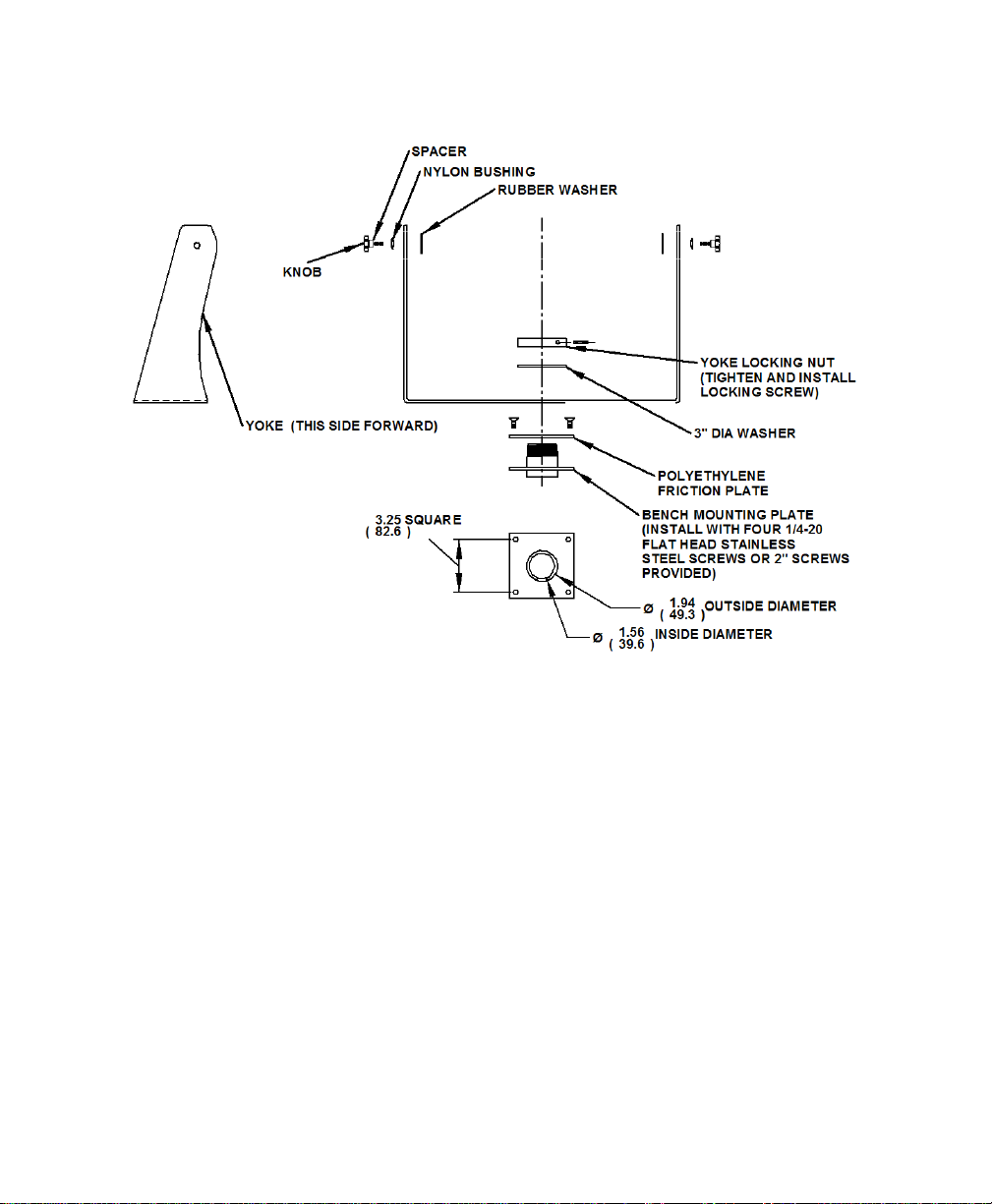
Installation using the yoke and benchtop mounting option.............................................................10
Installation using yoke and pedestal mounting option....................................................................11
Installation using fixed pedestal mounting option...........................................................................13
Touchscreen Driver Installation........................................................................................................15
Cleaning..............................................................................................................................................15
Resistive Touchscreen model........................................................................................................15
Tempered Anti-Reflective Glass Window.......................................................................................15
Acrylic Window..............................................................................................................................15
Troubleshooting.................................................................................................................................16
Drawings.............................................................................................................................................18
Specifications.....................................................................................................................................19
Display...........................................................................................................................................19
Environmental................................................................................................................................19
Video.............................................................................................................................................20
Electrical........................................................................................................................................20
Functional......................................................................................................................................20
Enclosure ......................................................................................................................................21
Physical.........................................................................................................................................21
Compliance ...................................................................................................................................21
VGA Pin assignment .....................................................................................................................21
Factory Preset Timing........................................................................................................................22
Warranty Statement ...........................................................................................................................23

3
Safety and Regulatory Information
Warning
To prevent fire or shock hazard, do not expose the unit to rain or moisture. Dange-
rously high voltages are present inside the unit. Do not disassemble the unit. Refer
servicing to qualified personnel only.
This equipment is not intended for use in critical applications where its failure to op-
erate would create immediate life threatening circumstances. Applications including
but no limited to nuclear reactor control, aerospace navigation systems and life
support systems are not appropriate for this product.
This product is intended to be mounted in a suitable cabinet or other enclosure. The
NEMA 4, 4x or 12 ratings are applicable only when properly installed in a like rated
enclosure.
This product is a UL Recognized Component and must be used with a listed com-
puter.
FCC Notice
This equipment has been tested and found to comply with the limits for a Class A digital
device, pursuant to Part 15 of the FCC Rules. These limits are designed to provide rea-
sonable protection against harmful interference when the equipment is operated in a com-
mercial environment. This equipment generates, uses, and can radiate radio frequency
energy and, if not installed and used in accordance with the instruction manual, may cause
harmful interference to radio communications. Operation of this equipment in a residential
area is likely to cause harmful interference in which case the user will be required to correct
the interference at his own expense. Any changes or modifications not expressly approved
by the grantee of this device could void the user’s authority to operate the device.

4
Control Panel Buttons and Indicators
Control Panel Button Mode Description
MENU Always
Opens the OSD menu. Also used to exit the OSD
menu or return to the previous menu.
Note: Pressing the menu button for more than 5
seconds will lock the OSD function, repeat to unlock.
-
When the
OSD Menu is
NOT
Displayed
MagicBright: Provides an optimum viewing envi-
ronment depending on the contents of the image you
are watching. Six different modes are available.
Each mode has its own pre-configured brightness
value:
1) Text: For documentation or work involving
heavy text
2) Internet: For working with a mixture of images
such as text and graphics
3) Movie: For watching motion pictures such as a
DVD
4) Game:For moving pictures such as a video
game
5) Sport: For moving pictures such as sports
6) Custom: Although the values are carefully cho-
sen by our engineers, the pre-configured values
may not be comfortable to your eyes depending
on your taste. If this is the case, adjust the
Brightness and Contrast using the OSD menu.
When the
OSD Menu is
Being
Displayed
Adjusts items in the menu DOWN.

5
Control Panel Button Mode Description
+ When the OSD
Menu is NOT
Displayed
Push to adjust brightness.
When the OSD
Menu is Being
Displayed
Adjusts items in the menu UP.
ENTER When the OSD
Menu is Being
Displayed
Activate a highlighted menu item.
AUTO
Always
Use this button for auto adjustment of the display.
Auto adjustment allows the monitor to self-adjust
to the incoming video signal. The values of fine,
coarse and position are adjusted automatically.
Auto adjustment will also occur automatically
each time the computer resolution is changed.
POWER Use this button to turn the monitor on and off.
POWER
INDICATOR This light glows green during normal operation,
and blinks green once as the monitor saves your
adjustments.

6
OSD Functions
Picture
Menu
Description
Brightness
Direct Access Feature: When OSD is not on the screen, push the
button to adjust brightness.
Contrast
Adjust the contrast.
Color
Menu
Description
MagicColor
Off: Returns to the original mode
Demo: The screen before applying MagicColor
appears on the right and the screen after applying
MagicColor appears on the left
Full: Displays not only vivid natural color but also
more realistic natural skin color with clarity
Intelligent: Displays vivid natural color with clarity
MagicZone: MagicZone ensures clear and
sharp display of animated multimedia or photo images by
enhancing the brightness, sharpness, saturation, hue of a
certain area on the screen
•Hue - adjust the hue of the MagicZone
•Saturation - adjust the saturation of the MagicZone
•Brightness - adjust the brightness of the MagicZone
•Sharpness - adjust the sharpness of the MagicZone
•H-Position - move the MagicZone horizontally
•V-Position - move the MagicZone vertically
•H-Size - adjust the horizontal size of the MagicZone
•
V-Size - adjust the vertical size of the MagicZone

7
Color Tone
The tone of the color can be changed and one of four modes can be
selected – Cool, Normal, Warm and Custom.
Color Control
Adjust individual R,G,B color balance.
Gamma
Select one of three pre-defined gammas:
•Mode 1 : Shows normal gamma
•Mode 2 : Shows higher gamma(brighter)
•
Mode 3 : Shows lower gamma(darker)
Image
Menu
Description
Coarse
Removes noise such as vertical stripes. Coarse adjustment may move
the screen image area. You may relocate it the center using the Horizon-
tal Control menu.
Fine
Removes noise such as horizontal stripes. If the noise persists even af-
ter fine tuning, repeat it after adjusting the frequency (clock speed).
Sharpness
Sets the clarity of the image.
H-Position
Changes the horizontal position of the display.
V-Position
Changes the vertical position of the display.

8
On-Screen Display (OSD)
Menu
Description
Language
Changes the language used in the display menu.
H-Position
Changes the horizontal position of the OSD.
V-Position
Changes the vertical position of the OSD.
Transparency
Changes the translucency of the background of the OSD.
Display Time
The OSD menu will automatically turn off if no adjustments are made
for a certain time period.
You can set the amount of time the menu will wait before it turns off.
Setup
Menu
Description
Image Reset
Image parameters are replaced with the factory default values.
Color Reset
Color parameters are replaced with the factory default values.
Information
Menu
Description
Information
Shows the video source and display mode.

9
Installation Instructions
Preparing for Installation
Important! Perform the following steps BEFORE installation of the monitor.
1. Ensure that sufficient power is available.
2. Ensure that sufficient space is available to allow for proper airflow
around the en-
closure.
3. Ensure that the air temperature around the unit (top and bottom) will not exceed the
rated specifications of the unit
.
•The maximum rated temperature of the HIS-UM17 is 45°C (113°F).
•Also, remember that even though this product is designed to operate
at 45°C , the life span of any electronic device is shortened when it is
consistently operated at high temperatures. Therefore it is wise to take
steps to keep the temperature of the ambient air around the unit as low
as possible.
4. Ensure that the ambient humidity of the air around the unit
does not exceed the
rated specifications for the unit
•The maximum rated humidity for the HIS-UM17 is 90% non-condensing.
Installation using VESA mounting
All units come standard with a 100mm square VESA mounting pattern with M4 threads. If
this mounting method is used, consider the following:
•M4 screws should not protrude into the rear cover by more than 1/4”.
•The capacity of the arm or mounting plate selected should take into account
the total weight of the monitor and its center of gravity.
•For NEMA 4/4X applications, the mounting interface should be properly
sealed to prevent egress of water. Sealing washers are provided for this
purpose.

10
Installation using the yoke and benchtop mounting option
1. Insure mounting surface is smooth enough to seal with gasket and create mounting
pattern in surface per the above diagram.
2. Install first two opposing ¼-20 flat head screws (two different lengths provided)
3. Rotate yoke 90 degrees to gain access to install remaining two screws.
4. Remove cap from end of threads if routing cables through the center of the plate.

11
Installation using yoke and pedestal mounting option
1. Prepare the mounting surface for installation of the pedestal by referring to the illustra-
tion.
2. Install the pedestal using appropriate hardware and methods for the mounting sur-
face selected taking strength, cable routing and sealing into
consideration.
3. Position and support the yoke assembly near the top of the pe-
destal.
4. Thread monitor cables through the yoke assembly (the ends of
the cables opposite the cover plate that joins to the monitor).
5. Connect all cables from the monitor into the pedestal. Connec-
tors that do not have a locking mechanism should be sheathed
in heat shrink tubing or tie wrapped to insure that they do not
come loose inside the pedestal.
6. Feed all connectors and excess cabling inside the top of the
pedestal.
7. Feed all cables into the space available inside
pedestal.
8. Install pedestal top plate using the four ¼-20 x ¾”
long screws provided. Access to the screws is
gained by the clearance notches in the yoke.
9. Feed remaining cable into the pedestal and screw the conduit elbow onto the top of the
pedestal taking care to position the direction of the conduit to allow free tilting of the
monitor without interference. Conduit elbow will pivot somewhat even after pipe nut is
tightened.
10. Install monitor onto yoke with the Yoke Hardware Installation Guide provided.
11. Install cables into the monitor securing video cable and touch serial cable with screw-
locks.
12. Remove and reuse screws to install cover plate onto monitor. Tighten all eight screws
of cover plate fully then back off one full turn.

12
Installation using yoke and pedestal mounting option (continued from previous page)
Note: The ¾” conduit and other sealing hardware are not required for NEMA 12 monitors or
NEMA 4/4X monitors with the 4-cable gland.

13
Installation using fixed pedestal mounting option
1. Prepare the mounting surface for installation of the pedestal by referring to the illustra-
tion.
2. Install the pedestal using appropriate hardware and methods for the mounting surface
selected taking strength, cable routing and sealing into consideration.
3. Install cables into the monitor securing video cable and touch serial cable with screw
locks.
4. Remove and discard hardware shown in the illustration.
5. Remove and reuse hardware shown in the illustration to install the cover plate.
6. Position and support the monitor so that the cables exiting from the monitor can be
easily routed into the top of the pedestal.
7. Remove and reuse the acorn nuts and sealing washers to install the monitor onto the
pedestal feeding cables into the pedestal.

14
Installation using fixed pedestal mounting option (continued from previous page)

15
Touchscreen Driver Installation
The enclosed CD-ROM contains documentation and drivers for all major operating systems.
To be sure you have the most current information, check the following Internet addresses:
http://HISmonitors.com/Touchscreen_Drivers.htm
Cleaning
CAUTION! DO NOT USE ABRASIVE MATERIALS SUCH AS PAPER TOWELS OR
DIRTY SHOP RAGS ON THE DISPLAY AS IT WILL SCRATCH THE PROTECTIVE
COATING. ALWAYS USE A SOFT CLOTH, PREFERABLY MADE OF COTTON.
Resistive Touchscreen model
Any standard glass cleaner can be used to clean the touchscreen. Always spray the glass
cleaner on the cloth or towel and then clean the touchscreen. Glass cleaner sprayed direct-
ly on the monitor could possibly leak inside a non-sealed unit and cause damage.
Vinegar or ammonia will not hurt the touchscreen. Again, spray the cloth and then clean the
touchscreen.
Tempered Anti-Reflective Glass Window
Use any standard glass cleaner as long as there is no abrasive or oily content. The anti-
reflective coatings are physically part of the surface of the glass and resist degradation to
the Military Specifications.
Acrylic Window
The acrylic front bezel can be cleaned in the same manner as the touchscreen or glass
window.

16
Troubleshooting
Symptom
Check List
Solutions
No image on the
screen Do you see the “Check Sig-
nal Cable” message on
screen?
Check the video connection from the monitor to
the computer.
If running Windows and the
computer power is on, reboot
the computer and watch for
the initial boot and windows
screen.
If you see the initial screens, then the image
goes dark, the computer may be set to an in-
compatible resolution. Reboot the computer in
safe mode and set the resolution and refresh
rate of the graphics card to a compatible reso-
lution
Do you see the “Not Opti-
mum Mode, Recommended
Mode 1280 x 1024 60 Hz”
message?
This message displays when the signal from
the computer exceeds the maximum resolution
and frequency that the monitor can handle. (>
1280x1024 resolution or > 85 Hz refresh rate).
Adjust the computer to a compatible resolution
and refresh rate.
There is no image on the
screen and the power LED is
blinking at 1 second inter-
vals.
The monitor is in Power Saver mode. Press a
key on the keyboard to activate the monitor
and restore the image on the screen.
The screen
shows strange
colors or dis-
plays in black
and white
Is the screen tinted to one
color as if looking at the
screen through cellophane
paper?
This occurs if not all signal cable connectors
are making contact.
Check the signal cable connection
OSD (On Screen
Display) will not
appear
THE OSD menu has been
locked.
Unlock the OSD by pressing the MENU button
for at least 5 seconds.

17
Symptom
Check List
Solutions
Image on screen
is not perfect
Many possible causes. Try
the following solutions. •Make sure the PC display resolution
matches one the factory preset timings
shown in this manual.
•Recall factory setting. Refer to panel con-
trols and OSD functions in this manual.
•Fine tune the picture by performing the fol-
lowing adjustments in this order – pitch,
phase, and position. Refer to OSD func-
tions in this manual.
Rolling or
unstable image
on screen
Many possible causes. Try
the following solutions. •Press “Auto” button.
•Change PC display resolution to
1280x1024 at 60 Hz refresh.
•Make sure the PC display resolution
matches one of the factory preset timings in
this manual.
•Unplug the power adapter to monitor and
then plug it in again.
•Press monitor power button again.
•Reset the monitor to the original factory
setting using the OSD.
•

18
Drawings
Front View
Side and Rear View

19
Specifications
Display
Type
Thin-film transistor (TFT) Active Matrix Liquid Crystal
Size
17” diagonal
Image size
13.3” (338mm) x 10.6” (270mm)
Native resolution
SXGA (1280 x 1024)
Plug and Play
DDC1/2B compatible
Minimum resolution
VGA (640 x 480)
Pixel pitch
0.264mm x 0.264mm
Number of colors
16.2 million
Viewing Angle (Hori/Vert)
160
°
/ 160
°
, typical
Brightness (white)
300 nits (cd/m2) max
Contrast ratio
600:1 (typical)
Back light
Four CCFTs (Cold Cathode Fluorescent Tube); 50,000
hours brightness half-life; replaceable
Screen protector (when
not shipped with touch-
screen)
Tempered glass to ANSI-Z97.1 SPEC; AR coated on both
sides; 98% Transmission of light; 99% Reduction of glare;
53% UV blocking; 30% NIR Blocking; proprietary hydro-
phobic coating on outside reduces fingerprint smears, repels
liquid spills and makes glass easy to clean.
Environmental
Temperature
0-45
°
C
Humidity
20% to 90% non-condensing
Shock
30g (1/2 sine, 11 msec.)
Vibration
0.006 inch p-p 15-57Hz, 1.0g 57-640Hz sine
Altitude
Operating: up to 10,000 feet; Non-operating: up to 40,000
feet

20
Video
Input connector
HD-15 (optional BNC input)
Input signal format
RGB Analog video
0.7Vp-p Positive at 75 Ohm +-10%
Separate H/V sync, Composite H/V sync, Sync on green,
TTL level positive or negative.
Horizontal scan 30kHz – 81kHz
Vertical scan 56Hz – 75Hz
Optimum Resolution
1280 x 1024 @ 60 Hz
Maximum Resolution 1280 x 1024 @ 75 Hz
Response rate (typical) 8ms
Electrical
Monitor input
100VAC – 240VAC (+/- 10%), 50/60Hz (+/- 3Hz)
Power consumption
Less than 34W
Power management
DPMS/energy star, < 1W
Compliance UL 60950 3
rd
Edition, cUL recognized component;
FCC Class A
Functional
Panel controls (rear
access) Menu, MagicBright, Brightness Adjust, Enter, Auto, Power,
Power Indicator
OSD (On Screen Display)
controls
Picture, Color, Image, OSD, Setup, Information
Touch screen option
5-wire resistive system; emulates a mouse; Serial RS-232
and USB interface to host computer
Table of contents
Other Hope Industrial Systems Monitor manuals

Hope Industrial Systems
Hope Industrial Systems HIS-ML18 User manual

Hope Industrial Systems
Hope Industrial Systems HIS-ML22 C Series User manual

Hope Industrial Systems
Hope Industrial Systems HIS-ML18B User manual

Hope Industrial Systems
Hope Industrial Systems HIS-ML21-CGBC User manual

Hope Industrial Systems
Hope Industrial Systems HIS-RL17-H Series User manual

Hope Industrial Systems
Hope Industrial Systems HIS-ML21-*** D series User manual

Hope Industrial Systems
Hope Industrial Systems HIS-ML12-SXA User manual