Chennai Metco BAINMOUNT Mounting Press - P User manual

BAINMOUNT
Mounting Press - P Manual
Instruction Manual
Pneumatic Mounting Press
Chennai Metco

Bainmount Pneumatic Page 2
Intended usage
When sectioned samples or components are irregular in shape,
mounting is an essential step for further processing. Based on the
requirement of quality and characteristics of the mould, proper
mounting material should be selected. With the appropriate mounting
material, and right mounting parameters high quality mounts can be
obtained with Bainmount mounting machine.

Bainmount Pneumatic Pag3
Contents
1. Safety -------------------------------------------------------------------------------------- 5
2. Transport ----------------------------------------------------------------------------------- 6
3. System Features and Principles of Operation ---------------------------------------- 7
4. Machine Layout ----------------------------------------------------------------------- 8
5. Installation ---------------------------------------------------------------------------------- 9
6. Operation --------------------------------------------------------------------------------- 10
7. Maintenance and Inspection ------------------------------------------------------------- 11
8. Dismantling ------------------------------------------------------------------------------- 13
9. Technical Specification ---------------------------------------------------------------------- 14
10. Electrical Circuit ---------------------------------------------------------------------- 16
11. Warranty certificate ---------------------------------------------------------------------- 20
12. Contact us ---------------------------------------------------------------------------------- 21
Bainmount Pneumatic Pag4
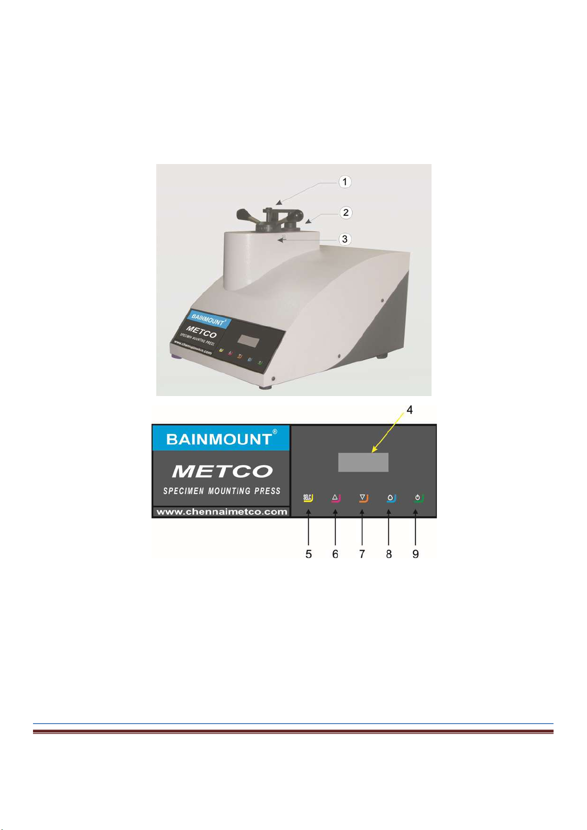
Take a Moment to familiarize yourself with the location and names
of the MP Pneumatic components.
1. Mould closure, 2.Mould Chamber, 3. Heater cover, 4. Display, 5.Parameter Selection
6. Parameter Increase/Ram Up, 7.Parameter Decrease/Ram Down, 8.Cycle Start/Stop
9.Power on/off

Bainmount Pneumatic Pag5
1. SAFETY
1 Safety
1.1 Proper Use
1.1.1 Principle
The Bainmount mounting press is state of the art and designed in accordance with recognized
technical research and experience and safety regulation. Failure or neglect to properly install, operate
and maintain the machine/system may be risk of serious or fatal injury to users or third parties or result
in unnecessary damage of the system or other equipment.
1.1.2 Permissible Operation
The machine/system is a technical working appliance, designed exclusively to Mount the materials
using polymers for easy handling during subsequent operations. Any other usage is regarded as
improper. Any liability on the part of the customer for damages resulting from an improper machine
usage is excluded. The risk has to be borne entirely by the user. The following are the example of the
machine/system misuse:
Using incorrect parameters resulting in damage of the holder..
Using on other industry or application.
Using other than recommended mounting polymers on the machine.
Untrained and unaccomplished this instruction manual personnel operated this machine/system
Proper usage also includes compliance with operating, servicing and maintenance requirement
specified by the manufacturer.
1.1.3 Safe operation of machine
The machine must only be used in a technically error – free condition and according to proper operating
practice in a safety and risk conscious manner while observing and heeding all caution or danger tags
attached to the machine or included in this manual
Malfunction that can impair safety must be remedied immediately.
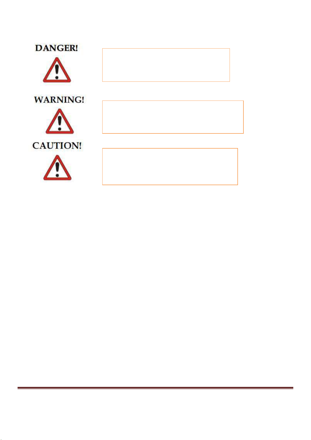
1.2 Level of hazard
This symbol is used to call attention to hazards or unsafe practices which could result in an injury or
property damage. The signal words, defined below, indicate the level of the hazards. The message after the
signal word provides information for preventing or avoiding the hazards. While reading your manual pay
close attention to areas labeled the signal words.
Bainmount Pneumatic Pag6
1.3 Safety information
Read and understand all the instruction and safety information in this manual. Everyone who works on or
around this equipment including, but not limited to, operator, maintenance personnel, and supervisory
personnel must read and understand the information in this chapter prior to commencing work on or around
this equipment. Failure to conform to the information in this chapter could lead to property damage or
serious personal injury including possible loss of body parts or death. This chapter only describes proper
safety procedures to follow when working with this equipment. Please refer to the instruction manuals
delivered together with the installation of your equipment.
Please ensure that all work described in this manual is carried out in a good environment / workshop using
proper tools and equipment.
1.4 Protection for Installation, Operation and Maintenance Personnel
In addition to the safety information included in this section, always observe all specific safety information
included with the instructions in balance of this manual. As manufactured this equipment has been equipped
with safety devices which correspond to current technology standard in accordance with the prescribed
applications of this equipment. However, residual risks remain to which attention is drawn individually
within this machine manual.
Instruction obligation: The operating company must verify that:
Personnel have the necessary technical, equipment-specific, and safety knowledge or that is
achieved by means of relevant training before the equipment is installed, operated, or
maintained.
Personnel have the necessary competence to be able to work on accordance with the regulations
and instruction.
Indicates an imminently hazardous situation
that, if not avoided, will result in death or
serious injury.
Indicates a potentially hazardous situation that,
if not avoided, could result in death or serious
injury.
Indicates a potentially hazardous that, if not
avoided, might result in minor or moderate
injury. It can also indicate possible loss of
materials or damage to the equipment.

Bainmount Pneumatic Pag7
Before initial startup, personnel have to read and understand all instructions contained within the
supplied documentation.
Equipment obligation: The operating company is required to equip personnel with the necessary protective
clothing as follow:
Safety shoes.
Safety goggles
Safety gloves
1.5 Protection for Third parties
The operating company must also make persons who are not charged with the operating or maintenance of
the equipment aware of the dangers.
1.6 Common Sense safety
Accidents frequently occur due to carelessness or lack of knowledge. To avoid potential problems, review
the information in the section before attempting to install, setup, operate, or maintain this equipment. Think
safety at all the times. Do not let familiarity with the equipment lead to unsafe short cuts. The following
common sense safety practices must be observed at all times.
1. Follow all procedures and precautions in the manual carefully and completely.
2. Only attempt repair or adjustments for which proper training has been completed.
3. Always observe all safety warnings and notices on the machine and in the manual.
4. Do not remove or otherwise alter any guards or panel unless the machine is completely shut
down and has been made inoperable. Be sure to replace these items before restarting the
machine.
5. Never operate the equipment without guards and safety mechanisms in place and functional.
6. Do not allow foreign object to fall into machine.
7. Always use the proper tools for performance of any operation on the machine. Whenever
feasible, use voltage-isolated tools.
8. Do not touch any parts of the machine which may have become hot during operation.
9. Do not wear neck ties, jewelry, loose clothing, and long hair.
10. Wear or use gloves, goggles, safety shields, ear protection, and other employer recommended
safety equipment. Wear protective clothing to prevent burns.
11. Disconnect power and lock out all switches before attempting to adjust or manipulate any
moving parts or mechanism on the equipment.
12. Be aware that there are high voltages in this device when power is connected. Power must be
disconnected when the device is being repaired. However, because there are certain checks and
adjustment that can be made only with any power connected, it is imperative that only trained
personnel, aware of the safety hazards involved and familiar with this type of work and
necessary safety precautions, be permitted to perform this work.
13. Maintain good housekeeping practices to prevent slips, spillage of mounting powders, cuts,
burns, and other possible accidents. Keep the area all necessary items properly organized.
Bainmount Pneumatic Pag8
14. Even though the plant may be equipped with automatic sprinklers or other means of the fire
protection, portable fire extinguishers should be available to the machine operator. To be
effective, portable extinguishers must be reliable, the proper type for each class of fire that may
occur in the area, in sufficient quantity to protect against the exposure in the area, located where
they are readily accessible for immediate use, and maintained in perfect operating condition.
They must be inspected frequently, checked against tampering, recharged as required, and
operable by are personnel who are trained to use them effectively and promptly.
1.7 Hazard Warning Label
Hazard warning labels are applied on the machine where potential hazards are potential hazards are
potentially present during operation and maintenance activities.
Hazard warning labels are in appropriate sizes and colors that catch attention of personnel’s eyes and have
symbols that show hazard types, in addition to descriptions of warning contents.
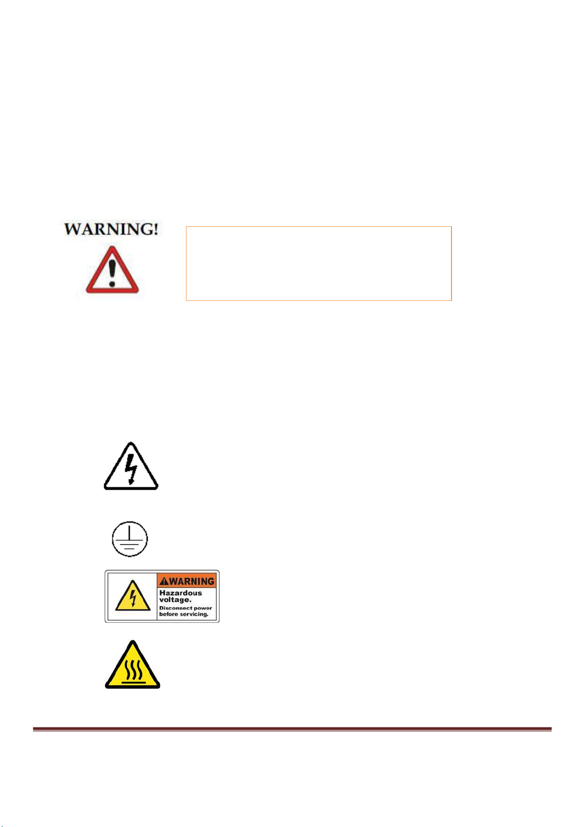
1.7.1 Types of Hazards Warning Label
The following safety warning labels appear on the system.
HOT
Personnel are requested to confirm the location
of, read and thoroughly understand contents of
all of hazard warning labels applied to this
machine prior to work.
“Warning of Dangerous Electric Voltage”
“Earth (Ground) Protective Conductor Terminal “
“Disconnect the power before open”
“Temperature can reach above 200
®
C ”

Bainmount Pneumatic Pag9
1.7.2 Location of Hazard Warning Label
.
1.8 Safety devices
1.8.1 Insulating chamber lock nut The handle of the mounting press is equipped with a insulating material that helps
to protect the operator from the heat during operation. Figure shows the insulating in the handle of the mounting
press.
1.9 Disposing Individual Component
Users are
NOT
allowed to change the location
of hazard
warning labels. Make sure to apply new labels upon
replacement of the peeled off or worn out labels
Reusable raw
material and problem material.
Environmental pollution.
Protect the environment by correctly disposing
of a recycling raw materials and problem
materials

Bainmount Pneumatic Pag10
Machine frame and all mechanical machine components are made of steel, light metal and plastics.
These materials are recyclable.
Take non-reusable difficult waste, lubricant and batteries, to the appropriate waste disposal point.
Seal any used parts possibly exposed to toxic or corrosive material prior, in inside of vinyl bags. Apply
certain marking to all of the disposal bags to identify possible contamination.
Be careful wh
ile handling waste fluid, which
may corrode
skin and clothing upon contact.
Bainmount Pneumatic Pag11
2. Transport
2.1 Unpacking and Inspection
Inspect equipment and shipping crate immediately upon receipt. Check the packing slip carefully and make sure
all the materials have been received as indicated on the packing ticket. If any damage apparent, you should both
report it to the trucking delivery person and contact the transportation company immediately. When submitting
a claim for shipping damage, request that the carrier inspect the shipping container and equipment.
2.2 Unpacking Location Environment /Cautions
Do not unpack in a location where any of the following conditions apply.
• Unbalanced
• Location with direct humidity (including rain and fog) intrusion
• Location with possible acute temperature change
• Location with strong vibration; also, do not place any product on such location
• Dusty
This symbol is used to call your attention to hazards or unsafe practices which could result in an injury or
property damage. The signal words, defined below, indicate the level of the hazards. The message after the
signal word provides information for preventing or avoiding the hazards.
While reading your manual, please pay close attention to areas labeled the signal words.
2.3 Transporting Machine with Box/Crate
Equipment and tools to be used:
Parallel jack
The forklift or lift truck employed must fulfill the following minimum requirements:
• Carrying capacity according to the total weight (machine/system and transport packing), see shipping papers.
• Length of the forks should be at least 920 mm
Interrupt the unpacking procedure and contact the
responsible forwarder once any obvious abnormality such
as abnormal noise/odor is found during unpacking.
Risk of falling transport items.
Risk of death or severe crushing of limbs
Careful lifting of the mounting press crate with parallel jack

Bainmount Pneumatic Pag12
i. Insert the fork carefully so that the centre of gravity of the box lies in the middle of the forks
ii. Lift it to a safe level so that the box can be moved to the required place
2.4 Unload Distribution Box
Equipment and tools to be used:
Forklift
Lift truck
Pallet Jack (figure )
The forklift or lift truck employed must fulfill the following minimum requirements:
• Carrying capacity according to the total weight (machine/system and transport packing), see shipping papers.
• Length of the forks should be at least 920 mm
• Distance between forks should be about 820 mm
Note: The centre of gravity of Distribution Box is not in the center and depends on the outfitting of the unit.
Risk of falling items.
Risk of death or severe crushing of limbs
Lift truck or forklift according to the total weight to be
transported
Fork length min . 920 mm fork spacing about 820 mm
Do not stand under the transport item during transport
Proper size of pallet shall be use or transportation
Lifting
equipment must be level with floor
during lifting occurrence

Bainmount Pneumatic Pag13
i. Place the Distribution Box into proper size of empty pallet.
ii. Place the fork lift insertion position on the pallet.
iii. Lift the pallet and transport to the installation site.
iv. Place Distribution Box according to installation plan.
2.5 Unload the Bainmount Mounting Machines
Equipment and tools to be used:
Forklift
Lift stand
i. Insert two lifting stand into the bottom four side of the Mounting Machine
ii. Place the fork arm into hollow section of lifting stand
iii. Lift the machine approx. 10 m and check the centre of gravity
iv. Transport the machine to the installation plan
v. Unload the fork lift to place the mounting machine on the floor
Risk of falling transport items.
Risk of death or severe crushing of limbs
Lift truck or forklift according to the total weight to be transported
Fork length min . 1250 mm fork spacing about 1000 mm
Position the forklift at the corresponding marked places of the crate
Do not stand under transport item during transport
Lifting equipment must be level with floor
during lifting occurrence

Bainmount Pneumatic Pag14
2.6 Relocating the Mounting Machine
2.6.1 Preparing for repositioning
Turn off the Main Switch of Electrical Control Panel and remove attachment of the main power
supply to system.
Remove the connecting pipe between Oil Tank and Distribution Box.
Secure all the parts on the Mounting machine
2.6.2 Repositioning of unit
Repeat the step on Section 2.4

Bainmount Pneumatic Pag15
3. System Features and Principles of Operation
3.1 Introduction
The Bainmount Mounting Press is exclusively designed for mounting the materials for metallographic
analysis. The machine offers that, mounting techniques can be programmed through a Programmable Logic
Unit (PLC) for various mounting materials. For this reason, the user can increase the quality and quantity of the
mount.
A user friendly Liquid Crystal Display (LCD) touch screen panel is provided on this system. Not much of
parameters required to determine before operation. User can choose the pre – existing recipes’ for the best
outputs.
3.2 Machine Description
Bainmount Mounting presses are exclusively designed for the metallurgical sample mounting. The machine
consists of a hydraulic motor that applies the pressure while a heater unit surrounds the mould wall which
increases temperature.
One of the advantages of the machine is the programmable mounting modes that facilitate mounting of various
polymers for increased edge retention and abrasion resistance. The advanced touch screen option allows the
user to enter and store the mounting parameters for easy storage and retrieval of mounting data.
3.3 Machine Content
The Bainmount Machines consists of the following assemblies
Electrical Control Panel assembly
Pressure control assembly
Temperature control Assembly
3.3.1 Electrical Control Assembly
The Electrical Control Panel consists of PLC, LCD display, 1-phase AC contactors, switches and etc. The
function of control panel is used to program the mounting cycle. The electrical assembly consists of pressure
indicator, temperature indicator, time and coolant on and off. The safety feature in electrical assembly includes
automatic cut off of pressure and temperature to limit the maximum pressure and temperature that can be
reached.
3.3.2 Pressure Control Assembly
The pressure control assembly includes the items of motors, tranducers, voltage indicator etc. Main function of
the pressure control assembly is not only increase and decrease pressure but also to maintain and limit the
applied pressure.

Bainmount Pneumatic Pag16
3.3.2 Temperature Control Assembly
The temperature control assembly consists of the thermocouple, temperature indicator, tube heater unit etc. The
temperature control assembly is used to monitor the working temperature inside the mold cylinder.
3.4 Working principle of the Bainmount Mounting presses
Initially when the mounting press is switched on, workpiece is placed with the surface of interest facing
downwards and the moulding powder is filled in the moulding chamber. With simultaneous application of
pressure and heat , the moulding powders melt and compact around the workpiece. Then the coolant is turned
on to cool the sample through water cooling tubes around mould cylinder to cool the mounted sample

Bainmount Pneumatic Pag17
4. Machine Layout
Bainmount Pneumatic Pag18
5. Installation
5.1 Installation Environment
Temperature : 5 to 40°C2
Humidity : 20 to 80% RH (no condensation)
5.2 Installation Space
Machine external dimensions (refer to Section 10.9) + working space (1000 mm)of footprint space
Machine height (refer to Section 10.9)
5.3 Environment and Operating Conditions
Ambient Temperature : 2 to 40º C when system is operational
Ambient humidity : 10 to 80% RH (no condensation) when system is operational.
Vibration : 2m/s or less at 10 to 50 Hz
Air cleanliness : An air dust volume of 0.2 mg/m3 or less is preferred.
In addition, there should be very little corrosive Such as hydrogen sulfide, zincate gas and
Chloride In addition, user should aware of following operating condition and
environment for the system:
• The unit should be installed in an area where is a good ventilation. Do not locate unit in area of wide
ambient temperature variation, such as near vent or outdoor entrances.
• Do not place the unit near combustible material or hazardous fumes or vapor.
• Make sure the unit is leveled when operation.
• Do not position the unit in a manner that would make it difficult to operate the Main Switch and
Emergency Stop button (at Electrical Control Panel).
Do not install the unit at the location as potentially
flammable and/or explosive atmosphere
Do not install the unit in a corrosive environment. A
corrosive environment may lead to poor performance and
deterioration of unit.
The system is not designed to be used at the location as
potentially flammable and /or explosive atmosphere

Bainmount Pneumatic Pag19
5.4 Making pipe connection
5.4.1 Connecting between Coolant tank and Machine
The recirculation coolant system connects pipe to and from the coolant tank which must be secured properly
without leakage. The pipe whose diameter is 7 mm fitted with the inlet to allow the coolant which is water to
enter the machine and hot water hose cable is connected to the outlet valve of the mounting press into the
coolant tank for recirculation.
5.5 Making Wiring connection
• The connection data can be seen from the wiring diagrams ( the wiring diagrams are sullied with
machine )
• The electrical connections require a Single phase connector cable
• Check the main voltage present against the voltage identified on the name plate to see if they match
• User must connect the incoming power supply to the terminal block as shown.
5.6 Connecting the compressor
The compressor is connected to the air pressure regulating unit in the mounting press via a 5 mm
diameter air pipe
Ensure sealed connection at the end to prevent
Do not loosen fitting to arrive at proper position or leak
may occur.
Over tightening may cause piper fitting to deform and
damage to the joining fitting
Remove all foreign matter from inside the piping
Work
ing on the electrical equipment must b entrusted
only to a trained and qualified electrician. The work has to
be carried ou according to the rules for electrical
engineering
Careful while handling the pressurized equipments and
only trained personnel should handle the machine

Bainmount Pneumatic Pag20
6. Operation
6.1
Machine Start up
6.1.1 Preliminary work before start – up system
The water to be used as coolant is to be filled in the tank.
The Main Switch and the coolant motor is switched on which is on the rear of the machine.
Ensure the Bainmount Press is set up before operation to be run.
6.1.2 Start up
The following steps must be obeyed and aware during start – up:
Step 1: Turn On the Main Switch on the rear of the mounting press
Step 2: Turn On the Coolant motor
Step 3: Once the mounting press software boots up, press the up option to raise the ram
Step 4: Spray mould release spray over the inside of the chamber of lock nut and on the ram surface for easy
removal of mould after mounting
Step 5: Keep the workpiece with the surface of interest facing downwards
Step 6: Press the down option to lower the ram
Step 7: Fill the mould cylinder with required amount of mounting polymer and close the chamber lock nut.
Ensure to clean the sides of the mould cylinder.
Step 8: Specify the temperature, pressure and time of heating and cooling to specify the mounting cycle
Step 9: Press the cycle start to start the mounting action
Step 10: After the mounting cycle has finished, open the chamber lock nut
Step 11: Press the Up option to raise the ram which brings the moulded workpiece to the surface.
Step 12: Remove the moulded workpiece and close the chamber lock nut. Ensure cleanliness of the machine
after use.
Ensure the coolant motor is running
before mounting operation starts
Table of contents
Popular Power Tools manuals by other brands

Porter-Cable
Porter-Cable US58 instruction manual

Metabo
Metabo W 17-150 Original instructions

Renfert
Renfert Vibrax 1830-000 Series instruction manual

Powermatic
Powermatic PF3-JR Operating instructions and parts manual

Universal Tool
Universal Tool UT1520C operating instructions

DeWalt
DeWalt DCF880-XE instruction manual


