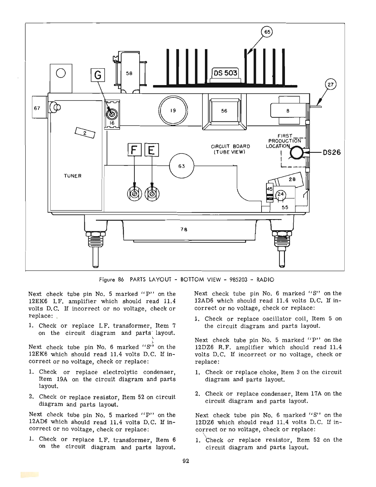
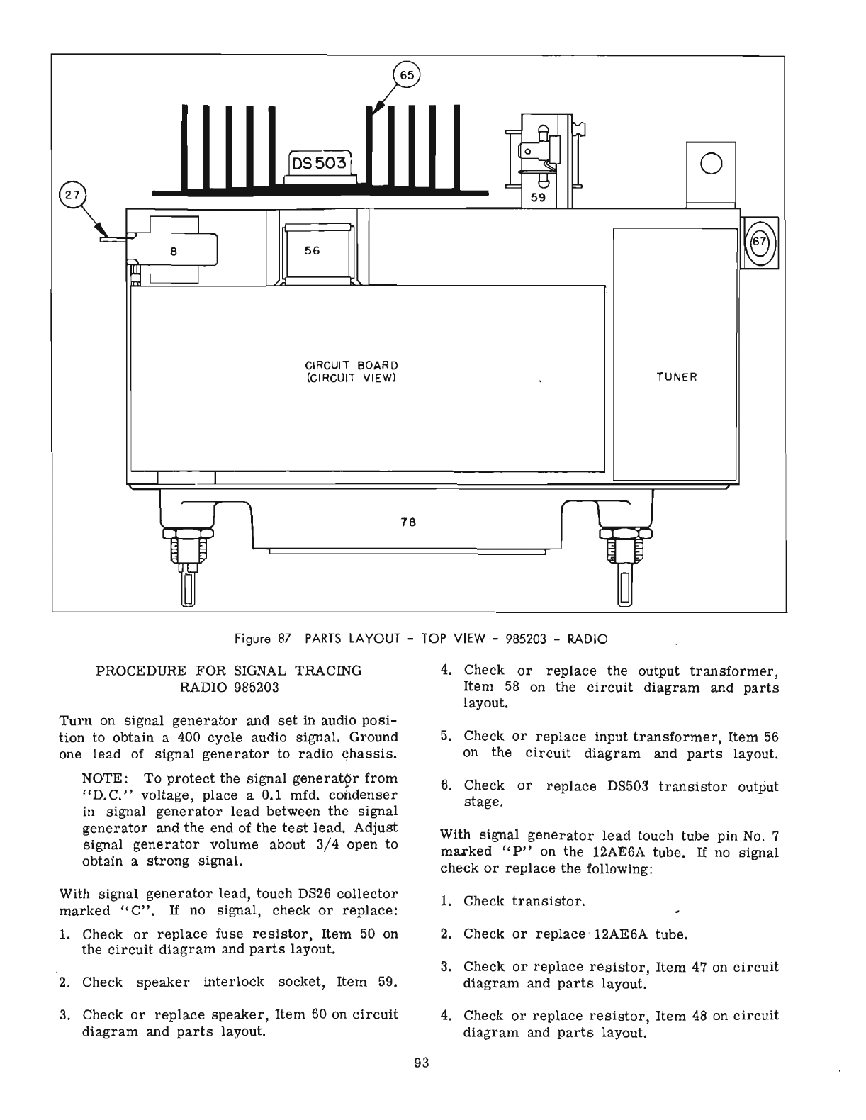
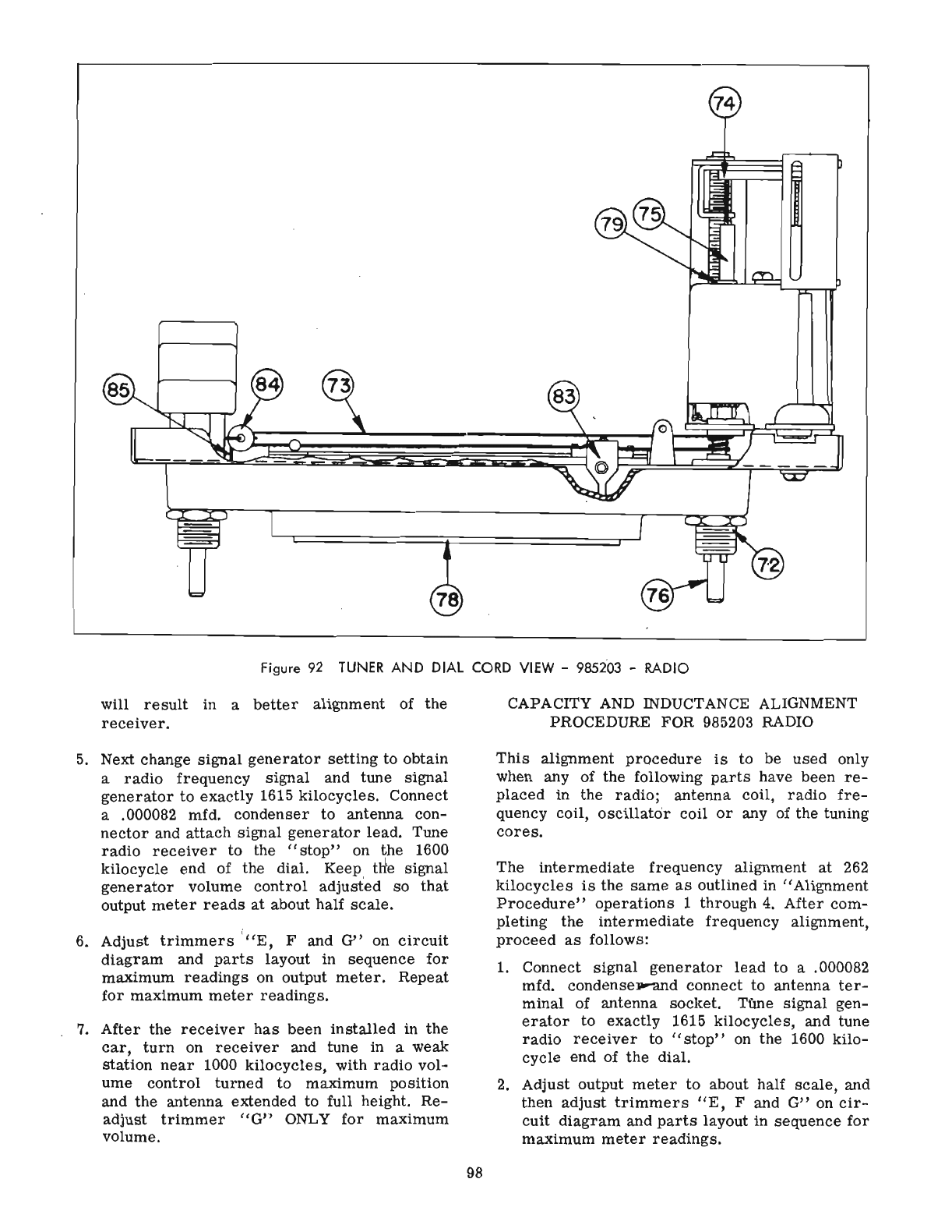
Figure
92
TUNER
AND
DIAL
CORD
VIEW
-
985203
-RADIO
will
result
in a
better
alignment
of
the
receiver.
5.
Next change
signal
generator
setting
to obtain
a
radio
frequency
signal
and tune
signal
generator
to
exactly
1615
kilocycles.
Connect
a .000082 mfd.
condenser
to antenna con-
nector
and
attach
signal
generator
lead. Tune
radio
receiver
to
the
"stop"
on the 1600
kilocycle
end
of
the
dial. Keep tlte
signal
generator
volume
control
adjusted
so
that
output
meter
reads
at
about
half
scale.
6.
Adjust
trimmers
·
"E,
F and
G"
on
circuit
diagram
and
parts
layout in
sequence
for
maximum
readings
on output
meter.
Repeat
for
maximum
meter
readings.
7.
After
the
receiver
has
been
installed
in
the
car,
turn
on
receiver
and tune in a weak
station
near
1000
kilocycles,
with
radio
vol-
ume
control
turned
to
maximum
pOSition
and
the
antenna extended to full height.
Re-
adjust
trimmer
"G" ONLY
for
maximum
volume.
98
CAPACITY AND INDUCTANCE ALIGNMENT
PROCEDURE FOR 985203 RADIO
This
alignment
procedure
is
to be
used
only
when any of the following
parts
have
been
re-
placed
in the
radio;
antenna
coil,
radio
fre-
quency coil,
oscillator
coil
or
any of
the
tuning
cores.
The
intermediate
frequency
alignment
at
262
kilocycles
is
the
same
as
outlined in
"Alignment
Procedure"
operations
1
through
4.
After
com-
pleting
the
intermediate
frequency
alignment,
proceed
as
follows:
1. Connect
signal
generator
lead
to a .000082
mfd. condensep.-and
connect
to antenna
ter-
minal
of antenna socket. T(me
signal
gen-
erator
to
exactly
1615
kilocycles,
and tune
radio
receiver
to
"stop"
on
the
1600 kilo-
cycle
end
of
the
dial.
2.
Adjust output
meter
to
about half
scale,
and
then
adjust
trimmers
"E,
F and
G"
on
cir-
cuit
diagram
and
parts
layout in
sequence
for
maximum
meter
readings.