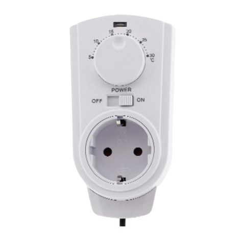
ChiliTec 23214 User manual

operation manual Status: 12/2021 - Version 1.00
page 1
Item No. 23214
Wireless thermal switch "Pilota Casa", IP20
433.92MHz, max. 70m, battery operation
From now on you can also control your Pilota Casa receivers in a temperature-controlled manner. Many different
setting options such as heating or cooling preselection, up to 8 different programs for weekly or daily settings, each
with an individual temperature, or manual switching of the receivers. In addition, the air humidity is shown in the
display.
Technical details:
• up to 8 individual day / week programs
• manual operation (ON / OFF) for existing Pilota
Casa receivers
• Continuous temperature test (approx. Every 10 seconds)
• shows the current temperature & humidity
• Compatible with all 433MHz Pilota Casa receivers
• compact design, HxWxD 100x64x16mm
• Operation with 2x AAA micro batteries (not included)
- Compatibility with other products / series / manufacturers
The "Pilota Casa" components with 433.92MHz are a closed system within the series. Compatibility with other
manufacturers or series would be purely coincidental. The Pilota Casa components use their own, encrypted
transmission protocol which prevents, for example, that a neighbor can operate your components with "the same
system" (thus perhaps switching your light on or off).
Within our Pilota Casa series, all 433MHz components are compatible with each other. You can teach in every
transmitter (wireless thermal switch, wall transmitter / switch, motion detector, remote control) on every receiver
(wall socket, flush-mounted switch, external socket).
Safety instructions and important information!
In order to guarantee safety at all times and to use the full performance spectrum of the device,
please read the safety instructions carefully and carefully!
The product must not be modified technically or mechanically, otherwise the operating license and conformity will
expire with immediate effect! The nameplate / imprint must not be removed under any circumstances! Check the
product for damage before each use. If the product is damaged, it must be checked, repaired or replaced by a
specialist company and disposed of in accordance with the applicable guidelines (footer page 1). Under no
circumstances may a damaged or defective product continue to be used!
Please be sure to secure all packaging material and accessories, especially small parts such as screws and foils,
from children and animals. Suffocation hazard! The manufacturer assumes no liability for property damage or
personal injury in the event of non-compliance with the instructions or improper use, misuse or changes made to
the product.
This product must never be operated, kept, stored or stored in the reach of children or animals. If this product is
passed on, the instructions and packaging must be included. Thanks!
We reserve the right to make misprints or changes to packaging, the product or the instructions.
Electronic products that are marked with the crossed-out garbage can do not belong in the household waste! You can hand these products in free of
charge at municipal collection points. Inquire at your local authority, the responsible town hall or a local or municipal waste disposal company.
Thanks very much. Used batteries should not be put in the household garbage. Consumers are legally obliged to bring batteries to a suitable
collection point at the trade or municipality. Old batteries may contain pollutants or heavy metals that can damage the environment and health. The
symbols under the label (garbage can) stand for: Pb: Battery contains lead, Cd: Battery contains cadmium Hg: battery contains mercury. The
environment and ChiliTec say thank you.
Reproduction only with permission from
ChiliTec GmbH, Bäckerberg 12, 38165 Lehr
EAR (WEEE): DE25841852
LUCID Packaging Act: DE5562476395648
GRS (UBA register) no .: 21003466
Translated from German to English - www.onlinedoctranslator.com

Status: 12/2021 - Version 1.00
Page 2
Item No. 23214
Safety instructions (only for 230V ~ / 50Hz components)
The installation or the intervention in the power grid can lead to very serious injuries up to a fatal electric shock. The
absence of voltage must be checked! • It is essential to observe the UVV (accident prevention regulations) and VDE
regulations! Operation only permitted on 230V ~ / 50Hz • Installation may only be carried out with approved and
tested tools • No assembly on or in the vicinity (50cm distance) of combustible / inflammable materials (ignition
temperature <200 ° C). Also watch out for gas
- / dust / room air mixture. If necessary, ventilate the room thoroughly beforehand. • Before doing any work, switch
off the circuit in which the installation is being carried out completely at the main fuse! Otherwise there is a RISK OF
LIFE !! • To connect all 230V ~ / 50Hz components, the minimum cross-section (1.5mm²) of the connection line must
never be undershot. It is imperative that you use a cable that has been expressly approved for this purpose. • There
are no parts to be maintained inside this product. • The correct connection must be checked;
• Operation is only allowed individually, installing in succession is prohibited!
First setup (connection) of the respective components
The two components must be “married” to each other once before being used for the first time. The connection then
remains permanent. To do this, follow the instructions on page 3. “Teaching in the transmitter”. The process only
takes a few seconds. Insert the batteries, with correct polarity, into the transmitter and switch it on (page 3, Fig. 3a).
Two or more receivers to be connected (e.g. socket) must have a minimum distance of 90cm from one another. The
radio connections are coded with a 24-bit key, which means that it is not possible to unintentionally teach in third-
party devices (e.g. with neighbors). Disturbance of the radio signal is also less likely. See also note on page 1,
compatibility with other manufacturers.
Connection of the socket version 23213
Plug the socket into a protective contact socket. After approx. 3 seconds the indicator LED (Fig. 1- shown in red) starts
to flash (or automatically when plugged in in the factory state!). The flashing signals the registration mode. If the LED
does NOT flash (approx. Every second) - Press and hold the ON / OFF switch of the receiver (Fig. 1 - red or green) for
approx. 3 seconds.
Functional level
Preselection mode Actual temperature
Program 1-8
Target temperature
Actual humidity
Actual day of the week
Actual time
Fig. 1 Start / end time
Fig. 1a
Two or more sockets to be installed must be at least 90 cm apart. The radio connections are coded with a 24-bit key,
which means that it is not possible to unintentionally teach in third-party devices (e.g. with neighbors). Interference
with the radio signal is also unlikely because the radio connection between the components is secure.
Reproduction only with permission from
ChiliTec GmbH, Bäckerberg 12, 38165 Lehr
EAR (WEEE): DE25841852
LUCID Packaging Act: DE5562476395648
GRS (UBA register) no .: 21003466

Status: 12/2021 - Version 1.00
Page 3
Teach-in of the transmitters, thermal switches, magnetic switches, motion detectors, FB etc. Item No. 23214
• First insert the battery into the respective transmitter with the correct polarity.
(See, for example, images) The battery compartments are located under the rocker switches (simply pull them off towards the
front) or, in the case of remote control / magnet and thermal switch, on the back under a flap.
• Switch on the power for the receiver (or plug in the socket). After approx. 3 seconds the indicator LED (Fig. 2
red) starts to flash (only in the factory state automatically when plugged in for the first time!).
The flashing signals the registration mode. If the LED does NOT flash (approx. Every second) - Press and
hold the ON / OFF switch of the receiver (Fig. 2 red) for approx. 3 seconds.
• The indicator LED flashes for approx. 12 seconds. During this time, new switching components (up to 10
different transmitters for one receiver) can be trained.
• During the 12 seconds in which the indicator LED is flashing, press the teach-in button (Fig. 3 ON button) on the
desired transmitter and hold it down until the indicator LED (Fig. 2) goes out. The two components are now
"married" and you can now operate the receiver (Fig. 2) via the transmitter (Fig. 3), or switch it on or off (with
the thermal switch in "Canecel" mode!)
• The programming is retained permanently, even in the event of a power failure. The same principle applies to all
other transmitter components such as the remote control. Learning a wall switch works in the same way, but to
log off press the OFF button "0" of the respective transmitter or "OFF" on the remote control or thermal switch.
• The learning (Fig. 3 OFF / 0 buttons) of BWMs / magnetic switches works in the learning mode of the receiver
(receiver button> 3 seconds no OFF button available) by also holding down the learning button of the transmitter
for 3 seconds. • Please note that reinforced concrete, stone, glazing and other radio components reduce the range
of the radio link.
Fig. 2 Fig. 3 Fig.3a
- Programming the transmitter (wireless thermal switch), explanation of the modes and functions
The two possible modes are heating or cooling function by default. In heating mode (sun), the OFF signal is sent when the preset temperature is
reached, and the ON signal when the temperature falls below this. In cooling mode (snowflake) it is exactly the other way round, since the ON signal
is sent when it is exceeded. To pre-set the mode (heating or cooling), go to the "CANCEL" function level by pressing the function key (FUNC) several
times. By simultaneously holding down the ON & OFF button (approx. 2 seconds), you switch the mode between sun & snowflake in the display. In
the "CANCEL" function level, you also set the day of the week and the time. To do this, select "CANCEL" and hold down the FUNC key for approx. 3
seconds. The day of the week over the time starts to flash. Make your choice using the + / ON and - / OFF buttons. A short press on FUNC then moves
on to the hours afterwards to the minute setting. In the "CANCEL" function level, you can use the + / ON and - / OFF buttons to operate a receiver that
has already been taught in. Another short press on FUNC changes to the next function level "MANU". In the "MANU" function level, you can set the
target temperature by holding down the FUNC key for approx. 3 seconds (.. and + / ON and - / OFF). When the target temperature is reached, the ON
or OFF signal is sent in the "MANU" function level, depending on the preselection mode (sun or snowflake). If you leave the thermal switch in the
"MANU" function level, this state repeats itself continuously (sending the ON or OFF signal). "MANU" is therefore actually the "constant temperature
monitoring" function without any week, day or time specifications. Briefly press FUNC to switch to the "AUTO" function level. Here you can switch
through the programs 1-8 with the + / ON and - / OFF buttons. For each of the 8 programs you can set separate target switching temperatures, days
of the week and start and end times (again by holding down the FUNC button for approx. 3 seconds). Since the navigation in all function levels is
carried out using just 3 buttons (pressed briefly and long), programming is much easier than it would appear after reading this text ;-) 1-8 switch
through. For each of the 8 programs you can set separate target switching temperatures, days of the week and start and end times (again by holding
down the FUNC button for approx. 3 seconds). Since the navigation in all function levels is carried out using just 3 buttons (pressed briefly and long),
programming is much easier than it would appear after reading this text ;-) 1-8 switch through. For each of the 8 programs you can set separate
target switching temperatures, days of the week and start and end times (again by holding down the FUNC button for approx. 3 seconds). Since the
navigation in all function levels is carried out using just 3 buttons (pressed briefly and long), programming is much easier than it would appear after
reading this text ;-)
Reproduction only with permission from
ChiliTec GmbH, Bäckerberg 12, 38165 Lehr
EAR (WEEE): DE25841852
LUCID Packaging Act: DE5562476395648
GRS (UBA register) no .: 21003466

EC declaration of conformity Status: 12/2021 - Version 1.00
page 4
Wireless thermal switch "Pilota Casa", IP20
433.92MHz, max. 70m, battery operation
Item No. 23214
Technical details:
• up to 8 individual day / week programs
• manual operation (ON / OFF) for existing Pilota
Casa receivers
• shows the current temperature & humidity
• Compatible with all 433MHz Pilota Casa receivers
• compact design, HxWxD 100x64x16mm
• Operation with 2x AAA micro batteries (not included)
The product must not be modified technically or mechanically, otherwise the operating license and conformity will
expire with immediate effect! The nameplate or imprint must not be removed under any circumstances! Check the
product for possible damage before each use. We do not accept any liability for damage to property or personal injury
for non-compliance with the instructions or improper use, misuse or improper use.
Declaration of Conformity (EG Declaration of Conformity)
Company / brand / EAN / item no. / Art. Designation / Manufacturer designation
(type)ChiliTec GmbH, Bäckerberg 12, 38165ehre-Essenrode, Germany
EAN: 4250416333438 / Art.No. 23214 / Designation: Wireless thermal switch / RSS502T
Product designation / time or date of first placing on the market:Wireless thermal
switch / February 2022
The product set has been tested according to the following standards / guidelines:
Component Art.no. 23214 RSS502T, (thermal switch)
EN 60950-1: 2006 + A11: 2009 + A: 2010 + A12: 2011 + A2: 2013 EN
62479: 2010
EN 301 489-1 V2.1.1
EN 301 489-3 V2.1.1
EN 300 220-1 V3.1.1
EN 300 220-2 V3.1.1
We hereby declare, based on the information provided by the producing factory, that the listed product fulfills the
conditions, necessary technical prerequisites and requirements with regard to electrical safety. Furthermore, the
directives of the council for the approximation of the legal regulations of the EU member states regarding the
electromagnetic compatibility (2014/30 / EU) and the Low Voltage Directive (2014/35 / EU) as well as ROHS (2011/65 /
EG) and the radio equipment Directive (2014/53 / EU) fulfilled. The authorization to carry the CE mark is fulfilled by the
conformity to the EMC / LVD / ROHS / RED directives.
Teaching, December 1st, 2021
place and date
T. Meyer
Name and signature
Electronic devices that are marked with the crossed-out garbage can do not belong in the household waste! You can hand these devices over to the
municipal collection points free of charge. Inquire at your local authority, the responsible town hall or a local or municipal waste disposal company.
Thanks very much.
Reproduction only with permission from
ChiliTec GmbH, Bäckerberg 12, 38165 Lehr
EAR (WEEE): DE25841852
LUCID Packaging Act: DE5562476395648
GRS (UBA register) no .: 21003466
Table of contents
Other ChiliTec Thermostat manuals
Popular Thermostat manuals by other brands

Termoventiler
Termoventiler Thermomatic EC Home Quickstart Guide for installation and first start-up

Fantini Cosmi
Fantini Cosmi CH150 manual

Glowworm
Glowworm Climapro2RF user manual

Pro 1 IAQ
Pro 1 IAQ T631W-2 operating manual

Ink Bird
Ink Bird ITC-310T-B user manual

Pro 1 IAQ
Pro 1 IAQ T755 Operation manual