Chinavision CVYY-I359 User manual

I
I
I
I
I
r
L
MINI HIGH SPEED DOME CAMERA
User Manual
PowcrSupply DC 12V
Factory Configuration: PELCOO protocol, Baud rate 2400, Address code 1
XPlease read carefully before using this manual
I:]
I--l
Ul:l
[]
W

I
i
I
i- _
I
I
I
Catalogue
Chapter 1 Product Summarize ------ 2
1.1 TechnicalParameters.............. ....-..----.----- 2
1.2 Function description............... -..-.-....----.-.- 2
Chapter 2 Equipment installation............ ...... 5
2:.1D/lP switch settings..... .................. 5
2.2 Dome camera stnrcture diagram..... --..---.,... 7
2.3 Bracket installation diagram..... .................- 9
Chapter3 System OSD menu settin9s................:..... ......10
3.1 Power-on self-test.. ..................10
3.2Presetpointsetringandcalling............... ....................10
3.2.1 Set preset points........ ...........10
3.2.2Call preset points........ ..........10
3.3 Preset pttintfunction table..... ....................10
3.4 <IAl1{ IEil1f.................:..... ...................11
3.5 <SYSTET Tf,FORIAIXIF ..........1 1
3.6 <AI'DR SETII{G>
3.72 €ET SGIX F(HrXlF...... 13
3.8.1 <PROGRAM PATTERtr' "'1 5
3.9 <CAMERA >(Lens) setting
3.10 <CRUISE> (preset points, 6uise settings) menu....................'......16
3.1{ <tR SETTING>.. ------.-17
3.12 <DISPLAYSETUD-.... .................17
Ghapter 4 Simple Tloubleshooting and Maintenance.........................1g
4.1 Simple TrouHeshoding Table.... ...........'.....1g
4.2 After Service ..........'..1g

r
Chapter I Product Summarize
Technlca!
1.2 Function description
1. Set address coding, baud rate, control
Any operation commands the camera
2
protocol
has its own
coding, baud rate, control protocol, a single camera only to respond with its
own address coding, baud rate, control agreement under the operatlon of
the command. Camera address coding, baud rate, control protocolspecific
settings please refer to the DIP settings.
2. Target tracking
Users can use the controls on the keyboard joystick control of the upper
and lower turning left and right cameras can be used to track moving
targets or moving horizon, while the focal length can be adjusted to change
the perspective of the size or the target image size. ln the auto-focus of the
state, with the lens rotation, the camera will automatically adjust according
to a rapid scene changes, instantly get a clear picture.
3. Focal length / speed automatic matching technique
Manual adJustment, the longer the focal length of the case, a reflection of
high-epeed ball machine makes a slight touch screen joystick may move
back, resulting ln data loss, Based on user-friendly design, intelligent ball
according to the proximlty of the focai length of the camera automatically
adJuats the horizontal and vertlcal speed, so that manual operation is more
simple and easy to track targets.
4. Auto turn over
The operator wlll pull the bottom of the lens (vertical) afier it is still holding
down the Joystlck, this time the level of the lens auto-rotated 180 ' turnihg
up immedlately after the 90 ', can directly watch the back of the scene in
order to achieve the full 180 ' continuous vertical surveillance.
5. Set and call preset position
Preset function is the current state of the ball under the PTZ function of the
horizontal angle, tilt angle and camera lens focal length, etc. position
parameters stored in memory you need to call these parameters can be
quickly andPTZ cameras will be adjusted to that location. The operatorcan
quickly and easily by controlling the keyboard, infrared controller, control
equipment such as storage and call the preset point, the ball machine to
support 256 preset polnts,
6. Lenc Control
(1) Zoom control
.1 Technlcal Parameters
Modelnumber 4INCH MINI HIGH SPEED DOME CAMERA
Opticalfocus 10x
lmage sensor 'l14"ccD
Signalmode PAL / NTSC
Resolution 48OTVL / s4OTVL / 65OTVL..
Opticalfocus ManualiAuto, adapt high performanoe DSP to rcrllzc
full digital high continuoua focualng funcilon.
Presets 256
Pattern scan 4 groups, each can record 100 actlons
Cruise scan 30 presets can Joln cruloo, can setflng the presets'
residence time.
Other scan Support Horizontal scan, deuce area scan, scan
random
Rotation range Horizontal 360'unlimted rotation, Vertical 180., auto
reversal
Rotation speed Florizontal & Vertical Min 0.01' Max 300'/s.
Communications PELCO-D and PELCO-P
OSD Full screen menu
Temperature
control svstem Optional
Power supply DC12V
Ballcover
dimension 4 inch opticalglass cover
Material Aluminum shell, waterproof lP66
Work
environment -20C-+50C(select temperature control accessories),
<95%RH
objectives address

Users can control the keyboard or through the ball machine to adjust the
focus of the distance matrix of the host, receive the necessary panoramic
images, or is a fine view.
(2) Focus Control
system default auto-focus, zoom, the camera lens will be the center of the
screen features auto-focus, to maintain a clear picture; in exceptional
circumstances, the user can manually focus, achieve the desired image
effect.
when in manual focus stiate, to restore the auto-focus, as long as the sway
bar can be restored remotely auto-focus. There is also a dedicated control
commands can be issued or to call an arbitrary way of restoring a preset bit
auto-focus.
The camera lens in the following situations will not autofocus on the
camera objectives:
a. Target is not to screen center;
b. Targets the same time in the far and near the place;
c. Target light objects, such as neon lighting, spo$ights and other
luminous objects;
d. Target with droplets or dust behind the glass;
e. Targets moving too fast;
f. Large area targets, such as walls;
g. Objectives are too dark or inherently ambiguous.
7. Aperture Control
users can control the keyboard to manuaily adjust the aperture slze to get
the required picture brightnese.
8. Auto Backlight Compenratlon
when the backlight compensatlon function is open, the camera lens in the
light background can be automatlcally targets the more the dark luminance
compensation. On the bright background light adjustment, to avoid the
background brightness caused by a mass of light throughout the picture,
goals and not identifiable because of the darkness to gain a clear image.
9. Auto White Balance
According to the changes in ambient light, automatic adjustment, the true
color reproduction.
10. Night vision function (color / monochrome conversion)
Cameras with night vision function, automatic color / monochrome
conversion mode, in accordance with changes in ambient light automatic
conversion CCD illumination. Such as: adequate lighting during the day
due to the use of general illumination to ensure colorful images. ln the night
illumination can be automatically changed to black and white images show
a clear interest.
11. Gruise
Can be pre-set cruise preset point, certain preset points, organized in the
order required to auto-cruise in the queue, only an external command can
be in an indoor speed ball set automatically according to preset points in
order to provide the time interval constant movement back and forth.
12. Pattern scannlng
Pattern scannlng machines to run the ballthrough the menu, the trajectory
is stored down by power-on action, free movement, alarm linkage, etc. to
callthe stored ecan llne.
13. Gontlnuour rcrn
Just an extemal command or through a power-on action, free movement,
alarm linkag€, etc. to call, can make the ball machine horizontal direction to
a certain speed the cycle of continuous scanning.
14. Batch Scannlng
Just an external command or through a power-on action, free movement,
alarm linkage, etc. to call, can make the horizontal direction the ball
' machine cycle of a certiain speed intermittent scan.
15. Area scan
Just an external command or through a power-on action, free movement,
alarm linkage, etc. to call, can make the ball machine horizontal direction to
a certain speed, within the limits set by the community and from scanning.
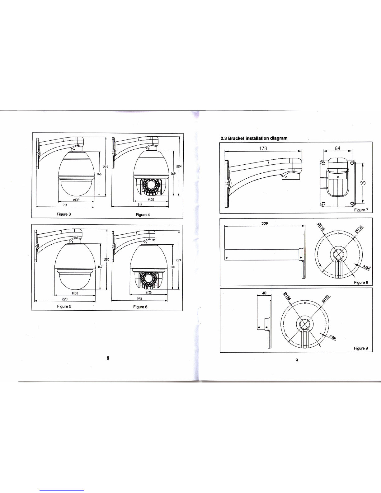
Chapter 2 EquiPment installation
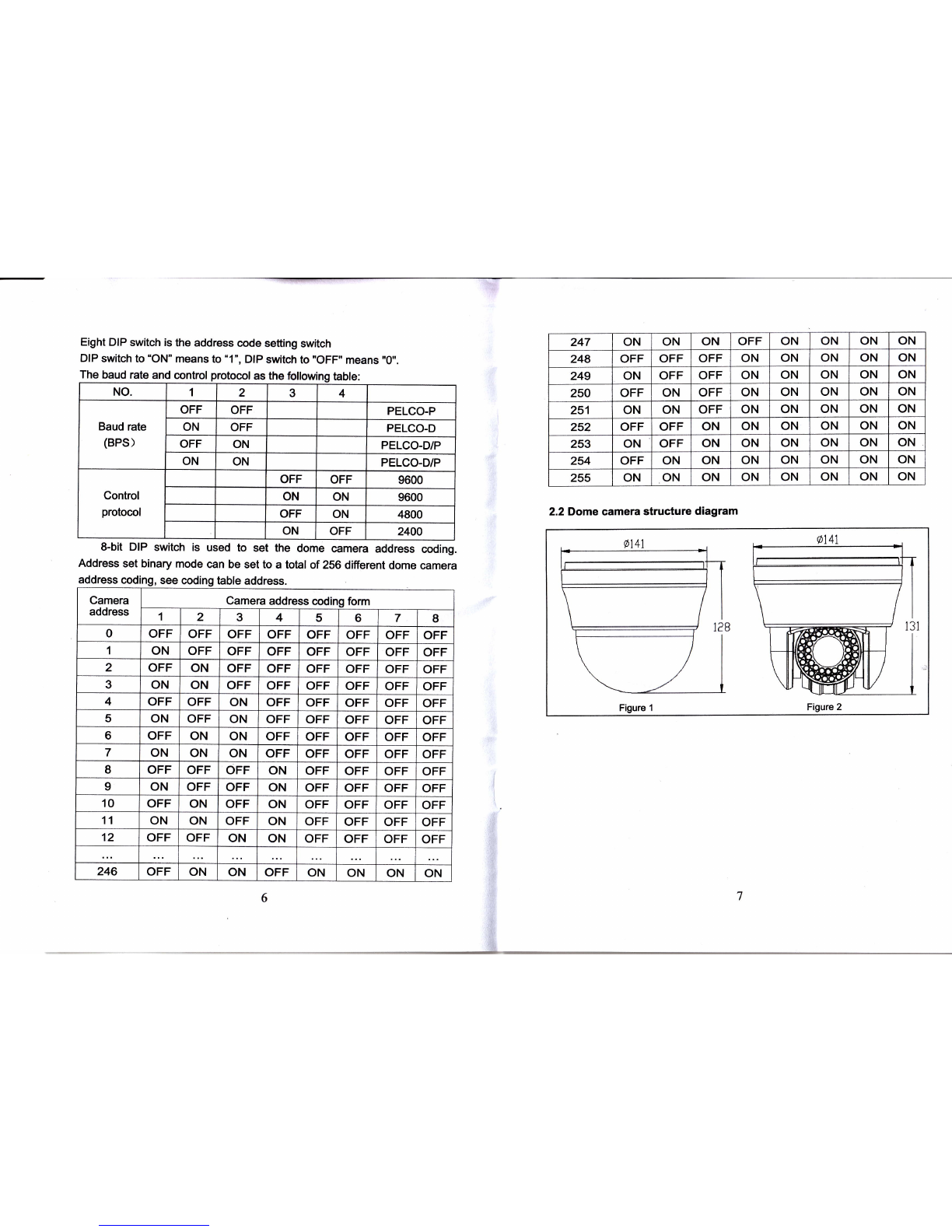
2.1 DIP rwltch rottlng
Four DIP swltch ls the baud rate and the control protocol switch.
5
i

baud rate and control protocol as the following table:
NO. 1234
Baud rate
(BPS)
OFF OFF PELCO-P
ON OFF PELCO-D
OFF ON PELCO-D/P
ON ON PELCO-D/P
Control
protocol
OFF OFF 9600
ON ON 9600
OFF ON 4800
ON OFF 2400
Eight DIP switch is the address code setting switch
DIP switch to "ON" means to'1", DIP switch to "OFF" means "0".
The
8-bit DIP switch is used to set the dome camera address coding.
Address set binary mode can be set to a total of 256 different dome camera
2.2Dome camera structure diagram
Figure 2
247 ON ON ON OFF ON ON ON ON
248 OFF OFF OFF ON ON ON ON ON
249 ON OFF OFF ON ON ON ON ON
250 OFF ON OFF ON ON ON ON ON
251 ON ON OFF ON ON ON ON ON
252 OFF OFF ON ON ON ON ON ON
253 ON OFF ON ON ON ON ON ON
254 OFF ON ON ON ON ON ON ON
255 ON ON ON ON ON ON ON ON
address coding, see coding table address.
Camera
address Camera address coding form
12345 6 7 8
0OFF OFF OFF OFF OFF OFF OFF OFF
1ON OFF OFF OFF OFF OFF OFF OFF
2OFF ON OFF OFF OFF OFF OFF OFF
3ON ON OFF OFF OFF OFF OFF OFF
4OFF OFF ON OFF OFF OFF OFF OFF
5ON OFF ON OFF OFF OFF OFF OFF
6OFF ON ON OFF OFF OFF OFF OFF
7ON ON ON OFF OFF OFF OFF OFF
8OFF OFF OFF ON OFF OFF OFF OFF
ION OFF OFF ON OFF OFF OFF OFF
10 OFF ON OFF ON OFF OFF OFF OFF
11 ON ON OFF ON OFF OFF OFF OFF
12 OFF OFF ON ON OFF OFF OFF OFF
246 OFF ON ON OFF ON ON ON ON

2.3 Bracket installation diagram
Figure 8
Figure 9
Figure 5
&

and vertical direction movement, the screen will appear system-related l
information, the dome camera self-test to complete the followinq diaoram. I
I\
Chapter 3 System OSD menu settings
3.1 Power-On Self.Test
When power is connected to the dome camera, the camera in horizontral
PTOL,. PELCO-D
coMM: 2400, N, 8, 1
ADDR: 1
Display: PELCO-D protocol. Baud Rate 2400. Address code 1
3.2 Preset point setting and calling
3.2.1 Set Preset points:
(1) selected camera (see manual control of the keyboard);
(2) operation Rocker, zoom button, focus bufton, buttons adjust the camera
aperture screen;
(3) Press the number keys + PRESET (input designated preset) to preserve
the scene preset parameters.
3.2.2 Call preset points:
(1) Selected camera;
(2) Press the number keys (inputs the designated preset) + PREVIEW
button, the camera immediately move to the preset position, the lens zoom,
focus and lris is also automatically change to the preset parameters; if the
input is a special function preset point (see "Preset Point menu"), the dome
camera will perform with special features preset point of the corresponding
functions (such as: Enter the 80th presets, the camera will perform
auto-tracking feature).
3.3 Preset point function table:
3.4 <MAIN MENU>
The dome camera power on and working properly, call the 95 preset
points into the main menu, screen display as shown in the Table
3-1.(Note:<lR SETTING> is for intelligent infrared dome camera special
function)
TABLE 3-1 MAINMENU
3.5 <SYSTEM INFORMATION>
)
11
Dialthe 86'nPresets use Pattern scan 3
Dialthe 87th Presets use Pattern scan 4
Dialthe 96th Presets 360-degree gap scan
Dialthe gTth Presets scan between two presets
Dialthe 98h Presets presets cruise
Dialthe 99th Presets 360 degree continuing scan
MAINMENU Menu function descriptions
SYSTEM
INFORMATION Displays camera basic information. ln the table 3-2.
ADDR SETTING Used to set the camera address. ln the table 3-3.
MOTION "PTZ" setup menu. ln the table 3-4.
PATTERNS Fancy scan setting; ln the table 3-5.
CAMERA Lens setting; ln the table 3-6.
CRUISE SETTING Preset point cruise setting; ln the table 3-7.
IR SETTING lnfrared light setting; ln the table 3-8.
DISPLAY SETUP Screen display setting. ln the table 3-9.
RESTORE FACTORY
DEFAULT Restore the factory default setting.
REBOOT SYSTEM System restart, the dome camera to power on reset.
EXIT Exit the OSD menu setting.
Dialthe 95th Presets Enter Main menu.
Dialthe 82nd Presets Auto Cruise
Dialthe 83th Presets clear all presets
Dialthe 84th Presets use Pattern scan 1
Dialthe 85th Presets use Pattern scan 2
SYSTEM INFORMATION Menu function descriptions
coM 2400,N,8,1 Serial information, display the dome
camera serial port baud rate, parity, data
bits, stop bits of information.
ADDRESS 1Display the current dome camera address
l0

code.
PROTOCOL PELCO.D Display the current dome camera
communication protocol.
PRESETS 256 Display the current dome camera preset
number.
SOFTWARE VERSION V5.2 Display the current software version.
BACK Return to main menu.
EXIT Exit the menu setting.
Note: The system information menu items under thls menu cannot be
changed.
PARK ACTION NONE Perform an action when the dome camera le ldle,
ln the Table 3-4-6.
FRAME SCAN SPEED
16 Set the area scan speed of the dome camera.
Within 1 (Slowest) -32 (Fastest).
RANDOM SCAN
SPEED 16
Set the intermittent scan speed of the dome
camera.
Within 1 (Slowest) -32 (Fastest).
BACK Return to the main menu.
EXIT Exit the menu setting.
TABLE 3-2 SYSTEM INFORMATION
3.6 <ADDR SETTING>
TABLE 3-4<MOTION>
3.7.1 <SET FRAME SCAN> (setting area scan)
Setting area scanning range, specific operations as shown in the
following table:
SCAN
3.7 <MOTION> (PTZ settings)
ADDR SETTING Menu function descriptions
ADDR TYPE HARD Divides HARD and SOFT; select the SOFT can
directly determine the dome camera address.
ADDRSOFT 1Within 1-254.
ADDRHARD 1
BACK Returns to main menu.
RESET To restore the default.
EXIT Exit the menu setting.
Note: Gan't mix up the soft and hard address seftings, would create the
dome camera out of control, setting reboot to be valld.
TABLE 3-3ADDR SETTING
FRAME SCAN Menu function descrlptlons
SET SCAN POSITION Set area scan position. ln the table 3-4-2.
CLEAR FRAME SCAN Clear area scanning setting. (Clear left and right
limit position). ln the table 3-4-4.
BACK Return to the previous menu.
EXIT Exit the menu setting.
TABLE 3.4.1 SCAN SETTING AREA
3.7.2 SET SCAN POS|T|ON
SET FRAME SCAN Menu function descriptions
LEFT LIMIT
POSITION
IRIS OPEN TO
CONTINUE
Shake the joystick to select the left limit position;
Press ffiilbutton to confirm the cunent position
of the left limit position, and enter the following table
34-3.
TABLE 3-4-2 SETTHE LEFT LIMIT POSITION
Menu is used to set PTZ parameters such as movement and orientation
As shown in the following table:
MOTION Menu function descriptions
SETFRAME SCAN Set the area scan to the left and right limit. ln the
table 3-4-1.
POWERUP NONE Power on setting menu. ln the table 34-5.
PARK TIME 15S How long to perform an action when the dome
camera is idle.
SET FRAME SCAN Menu function descriptions
RIGHT LIMIT
POSITION
IRIS OPEN TO
CONTINUE
Shake the joystick to select the right limit position;
Press f, button to confirm and return to the
table 3-4.
TABLE 3.4.3 SET THE RIGHT LIMIT POSITION
l3

3.7.3 CLEAR FRAME SCAN (Clear area scan location)
CLEAR FRAME SCAN
IRIS OPEN TO
CONTINUE
Press ! to cleai the left and right limit
position and return to the table 34.
TABLE 3-4-4 CAMERA SETTINGS MENU
3.7.4 <POWER UP>
The dome camera is powered on, didn't receive any instructions to perform
action. Parameters in the following table:
3.7.5 <PARKACTION>
TABLE 3.5 PATTERNS
3.8.1 <PROORAM PATTERN>
TABLE 3-5.2 PATTERN SCAN SETTINGS
3.9 <CAMERA> (Lens settings)
PATTERN 1Perform the pattern scan line 1
PATTERN 2Perform the paftern scan line 2
PATTERN 3Perform the pattern scan line 3
PATTERN 4Perform the pattern scan line 4
REAPEAT LAST Automatic recovery to the previous action.
CRUISE Perform the cruise scanning action.
TABLE 3-4-6 PARKACTION
POWER UP Menu function descriptions
NONE Don't perform any actions.
AUTO SCAN Perform continuous scanning action.
RANDOM SCAN Perform intermittent scanning action.
FRAME SCAN Perform area scanning action.
PRESET 1To reach the NO.1 preset point.
PRESET 8To reach the NO.8 preset point.
PATTERN 1Perform the pattern scan line 1
PATTERN 2Perform the pattern scan line 2
PATTERN 3Perform the pattern scan line 3
PATTERN 4Perform the pattern scan line 4
CRUISE Perform the cruise action of preset point.
TABLE 3-4-5 POWER UP MENU
3.8 <PATTERNS>
PATTERNS Menu function descriptions
PATTERN NUMBER 1Select pattern number, within 1-4.
PROGRAM PATTERN To select pattern scan line; Operations
shown in the table 3-5-1.
CLEAR CURRENT PATTERN Clear current pattern scan line.
CLEAR ALL PATTERN Clear all the pattern line.
BACK Return to the previous menu.
EXIT Exit the menu setting.
PROGRAM PATTERN Menu function descriptions
USE THE JOYSTICK OR
KEYBOARD TO MOVE THE
CAMERA TO THE STARTING
POSITION IRIS OPEN TO
CONTINUE
Use the joystick or keyboard to move the
camera to the starting position, and press
tre f, key to continue, and go to the
table 3-5-2.
TABLE 3.5-1 PROGRAM PATTERN SCAN SETTINGS
ln the idle time, the dome camera doesn't receive any instructions to
perform an action. ldle movement parameters as shown in the following table:
PARKACTION Menu function descriptions
NONE Do not perform any action.
AUTO SCAN Perform continuous scanning action.
RANDOM SCAN Perform intermittent scanning action.
FRAME SCAN Perform area scanning action. (lt will come into effect
after the SET FRAME SCAN is set).
FRESET,I Arrive the First preset point.
PRESET 8Arrive the Eighth preset point.
PATTERN Menu function descriptions
STORAGEUSED 1
Shake the joystick to editing the scanning line and
action, from the movement 1 began to record, up
to 100 movements. Press ffilkey to save the
settings and return to table 3-5.
t4 15

Languages Chinese/English
Multiples Display ON/OFF
AGC 180
Backlight compensation ON/OFF
Shutter setting AUTO
Focus setting AUTO
Brightness setting 110
Sharpness Setting 013
Day& night switch AUTO
Negative Set OFF
Lens Set OFF
Default setting OFF
TABLE 3-6 CAMEM SETTINGS
IR OFF SENS 23O Light intensity of lR light is close, within 81-254.
BACK Return to the previous menu.
EXIT Exit the menu setting.
TABLE 3-8 IR SETTING MENU
3.I2 <DISPLAY SETUP>
Chapter 4 Slmple troubleshooting and maintenance
DISPIAY SETUP Menu function descriptions
ZOOM ON/OFF Zoom display ON/OFF.
P/T DEG ON/OFF HorizontalA/ertical an gular coord inate display
ON/OFF.
BRIGHT DATA ON/OFF Light source data display ON/OFF.
IR DATA ON/OFF lR light data display ON/OFF.
BACK Return to the previous menu.
EXIT Exit the menu setting.
TABLE 3.9 SCREEN DISPLAY SETTINGS
3.10 <CRUISE> (Preset points, cruise
CRU!SE Menu function descriptions
DWELL TIME[SECS] 6Cruise waiting time between preset points.
PRESET LIST 1Cruise list of preset points. Total 3 pages, each
page can be selected 10 preset points.
1 ON OOFF
1234567890
PRESET
111',t111111
t1-101
Select preset points need to be involved in
cruise scan. The corresponding parameter is 0
and 1. Press ffi key to change, 1 is selected,
0 is skipped.
BACK Return to the previous menu.
EXIT Exit the menu setting.
TABLE 3-7 CRUISE SETTING MENU
4.1 Simple Troubleshootlng Table
Failure Posslble Cause Solutions
Electricity
without action,
no images,
light does not
shine.
Connected the
wrong power cord Corrections
Power supply is
damaqed replace
Bad fuse replace
Power cord
connection is bad Exclusion
Power are
self-test, there
are images, not
control
lR uniform dome
camera address
code, the baud rate
setting does not
To re-set the high-speed dome
address code and baud rate
Wrong protocol corrections
RS485line reversed Check wiring RS485 control line
3.11 <lR SETTING> (lR speed dome
IR SETTING Menu function descriptions
IR MODE AUTO ON: lR light is forced to open; OFF: lnfrared light is
forced to close; AUTO: lR light is switch
automatically.
IR ON SENS 250 Light intensity of lR light is open, within 81-254.

or open
Unable to
complete
self-test, there
are images
associated with
motor tweet
sound
Mechanical failure Maintenance
Camera Tilt Straightened
Power is not enough
Replacement to meet the
requirements of the power supply, it
is best to power the camera on the
near-infrared uniform
lmage
instability
Video line
connection is bad Exclusion
Power is not enough Replace
Blur Manualfocus on the
state
Operation of any infrared high
speed dome camera or call a preset
point
lR control of a
high-speed
dome camera
non-stop or
delay
Power is not enough
high-speed Dome
Replacement to meet the
requirements of the power supply, it
is best to power on the high-speed
dome camera in the vicinity
Check control of the
most distant
high-speed dome
camera match
whether to join the
resistance
The most far away from the control
of the ball-type cameras by adding
matching resistor
Far from 485 the
signal attenuation Bold Line of Control
Converter 485 is not
enouqh drivinq force Replacement of a source converter
4.2 Alter Service
Dear users, in order to ensure the full enjoyment of your camera services,
please read the following products and services charter.
(A): lR dome camera company limited warranty and lifetime
maintenance services
1. The limited warranty period from the date of sale for 12 months, in the
limited warranty period, you will enjoy the products fault free service,
delivered or sent by the user's maintenance (improper use of man-made
causes of failure or an irresistible. The fault does not belong to the scope of
the warranty).
2. ln more than 12 months limited warranty from the date of the product
life-long failure of the implementation of paid maintenance services.
(B): The dome camera repair response time
1. Users will be sent to the company from the date of product, 24-hour
response service.
2. Customers return products to our company, please advance with my
company-related contact, and then returned to our company products.
Otherwise, the situation appears not timely maintenance by the user
themselves.
Product Warranty Cards
this that every case of normal use the
caused bv failures in theto quallty problems caused by failures in the warranty period will
free
Warranty Description:
1. This product is free of charge warranty period of one year, during the
warranty period any product quality problems occur, so doing the warranty
card for free (non-human damage), life-long maintenance.
2. A result of improper use or other reasons as well as the failure of products
outside the warranty period can be so doing card repair, free of maintenance,
only the income component costs.
3. Product required maintenance should be a copy of this card and the
invoice with the product delivery of the Company or the local special
maintenance department.
4. Secretly open the dome camera casing, tearing up letters labeling,
according to the provisions of collecting maintenance fees and components
l8 t9

and other expenses.
5. Does not accept any modification or installation of other functions due to
failure after the dome camera.
The following conditions will not be free of charge Warranty:
1. Due to normal wear and tear caused by periodic inspection, maintenance,
repair or replacement parts.
2. As the fall, extrusion, soaking, damp, and other man-made damage.
3. Because of flood, fire, lightring and other natura! disasters or force
majeure of the factors that darnage-
4. By non-authorized repaircenbrs repdrtte machine ofi.
5. Listed above, if cfranges b the relevant gwiskrns shall prevail.
Remark:
I
1
I
l
I
i
l
ModelNumber
Factory Number
Date of
manufacture
Customer Unit
Name
Address
Telephone
Maintenance
date Failure condition Maintenance
site Maintenance
result
2A
Table of contents
Other Chinavision Security Camera manuals