Chinowing E11 User manual
E11
2022.3
V1.0.2
www. chinowing. com

Content
Disclaimer...........................................................................................................................................3
Product introduction................................................................................................................... 3
Item list................................................................................................................................................. 3
Main module............................................................................................................................ 3
Product instruction....................................................................................................................... 4
E11 and V21 installation diagram...................................................................................... 5
E11 Schematic diagram of network router components...................................... 5
E11 and V21 wiring diagram................................................................................................ 6
Use of LAN and serial ports.....................................................................................................8
V21 video transmission and E11 routing IP address distinction.......................... 8
LAN configuration using................................................................................................... 9
Seiral configuration using................................................................................................ 10
TCP seiral port connection using................................................................................ 14
Use of virtual seiral port connection......................................................................... 14
E11 serial port module one to one using.................................................................. 16
E11 seiral port working mode independent port distinction............................. 16
Common problem......................................................................................................................... 17
Historical version..........................................................................................................................18
2
www. chinowing. com
Thank you for purchasing E11 router(here referred as “E11”)Please read
this statement carefully before using.Once used,it is deemed to be the
recognition and acceptance of the entire content of this statement.Please
strictly follow this instruction to install and use the product. Chinowing
technology company will not bear any legal responsibility for any results or
losses caused by improper use,installation,assembly and modification by
users.
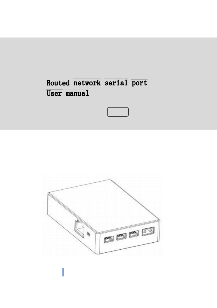
The E11 network router is mainly designed for not enough interfaces of network image
transmission,it provides three 100M LAN interfaces. Three network serial ports supports
TTL,RS232 hardware level,network protocol which supports TCP server ,TCP client, UDP client,
UDP server,and HTTPD client multiple working modes. Also it supports Modbus gateway
function;it supports T30 T40 V21 series and third party network image transmission,providing
abundant expansion interfaces.
Main module
3
www. chinowing. com

Accessories
Power cord x1
GH 1.25 to RJ45
GH1.25 4pin
Power the module ( DC:7.4-24V)
F or L AN in t e r f a ce
co n n e c t i o n
For serial port data connection
E11 has three LAN interface,three serial port,serial port including one TTL,two
RS232 level.If your level signal does not support TTL or RS232,you need to buy an
additional converting RS232 level module.Please connect the modules according to the
wiring diagram below:
4 www.chinowing.com
www. chinowing. com
5
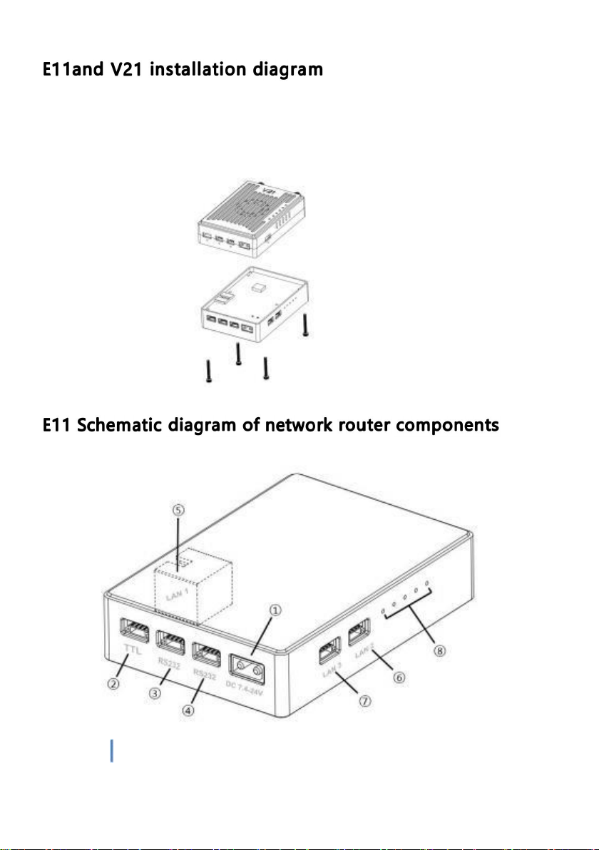
The E11 and V21 can be seamlessly connected. After taking out the V21 shell screws,
align them with the E11 screw holes, and use M2*18mm screws to connect the two
modules together. The schematic diagram is as follows:

①XT30
Power supply interface;
Support 7.4-30V
②TTL interface:full duplex serial port
③RS232 interface:full duplex serial port ④RS232 interface:full duplex
serial port
⑤⑥⑦ LAN interface 3
Used to transmit video or connect network devices
⑧Signal indicator;
L1 represents the power supply;
L2 indicates that there is equipment connected to LAN3 and it is always on;
L3 flashes to indicate that all LAN ports can work normally, and extinguishes to
indicate failure;
L4 is always on, indicating that the serial port self-test is normal, and off, indicating
that the serial port is faulty;
L5 flashes to indicate data transmission, and when it is off, there is no data
transmission;
6
www. chinowing. com
After the connection is complete, please refer to the following
steps to check the connection status. (This step will have some
differences due to different flight controllers)
TTL interface
RS232 interface
5V
5V
5V
5V
RX
TX
RX
TX
E11 GND
GND flight
controller or
other equipment
E11 GND
GND flight
controller or
other equipment
TX
RX
TX
RX
LAN interface
TX+
RX+
TX-
RX-
E11 RX+
TX+ Web camera or
other device
RX-
TX-
1. E11 is connected to 7.4-24V DC power supply, and the POWER indicator
light indicates that the transmitter is powered on normally; when the L2
indicator light is continuously on, it means that the LAN port self-test is
normal working;
2.When the L3 indicator is always on, it means that the serial port module starts
normally, and it can work normally after the self-test is completed;
3. Open the flight control ground station software, select the
corresponding COM port, and connect to the flight control. If the
flight controller is connected normally, it means that the data
transmission link of the E11 module has been connected. If the
connection fails, please check the following points:
1. Whether the baud rate of the device is consistent with that of
the E11.

2. E11 parameter settings can be registered in the browser to ensure that
all parameter settings on the device and E11 terminal are consistent.
3. Make sure that the RX of the flight controller corresponds to the TX of
the E11, and the TX of the flight controller corresponds to the RX of the
E11.
7
www. chinowing. com
V21 video transmission and E11 routing IP address distinction
Type
IP address
V21 ground terminal
192.168.168.11
V21 airborne
terminal
192.168.168.12
E11 serial port
192.168.168.19
E11 LAN*2
All the above IP addresses in the E11 can be logged in and accessed in the browser of the
PC to modify the parameter configuration.
In order to prevent users from problems such as not being able to search, not being able to
ping, and not being able to open web pages in the application. After the hardware is
connected, before use,
Check the computer first.
① Turn off the computer's firewall and antivirus software (usually in the control panel).
② Turn off the network card that is not related to this test, and only keep a local connection
or WiFi wireless connection.
③ The IP of the computer must be set to a static IP in the same network segment as the IP
of the V21, for example:
192.168.168.35.
V21 data link website login user name:admin123 Password:admin123
E11 serial port website log in user name:admin Password:admin
8 www.chinowing.com

LAN configuration using
1. After the LAN port of E11 is connected to V21, two IPC devices can also be
connected. If the computer needs to access two IPCs at the same time, the IPC
and the local IP of the computer must be set to the same network segment.
2. The LAN port of the V21 ground terminal is connected to the computer,
please make sure that the IP address of the local connection of the computer
and the camera are in the same network segment
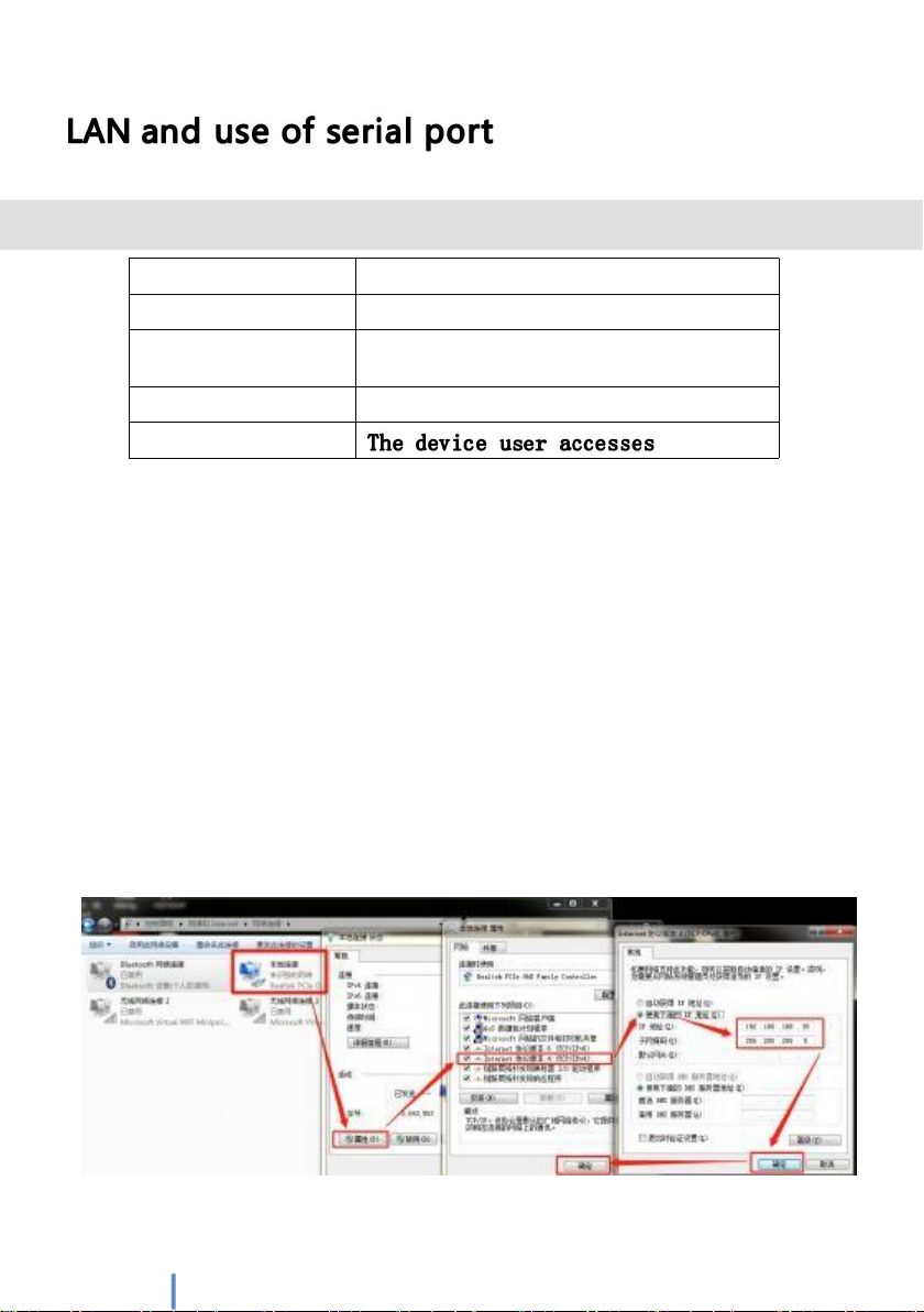
① Open the computer network sharing center
② Open the change adapter option
③ Select the local connection connected to the V21 ground terminal,
right-click to view properties
④ Select the Internet IPV4 protocol, set a fixed IP, and the IP is on the same
network segment as the camera, for example:
The camera IP is 192.168.168.100, except for setting the local IP to
192.168.168.xxx (0~255) 100, click "OK" after the change is completed.

⑥ Use streaming software such as VLC media player to capture
and play video data.9 www.chinowing.com

● If the LAN port is connected by cable, the IP address of the V21 can be ignored
when setting the IP when streaming video. Change the local IP of the computer to the
same network segment as the IP camera;
● It is recommended to set the ip network segment of the two LAN ports of E11 to
192.168.168.XX and V21 in the same network segment, so that the image and configuration
data of the LAN port and video transmission can be obtained at the same time;
● Pl e a se l o g i n to o u r w e bs i t e fo r s tr e a m i ng v i d e o o r mo r e t u to r ia l s ;
Serial port configuration using
The default baud rate of all serial ports of E11 is 115200,
and the default IP address; the ground terminal is
192.168.168.19, working mode: the air terminal is TCP Server,
and users need to use TCP Client mode to connect and access;
串口工作模式独立端口区分
Type
Working
mode
Local port
Level
signal
E11
TCP Server
10
TTL
20
RS232
30
RS232
If you need to change other configurations, you can connect to the
computer through the LAN port.
① The IP of the computer must be set to a static IP that is in the same
network segment as the E11 serial port IP. After connecting to the LAN, open
the network adapter and select the network adapter connected to the E11
serial port to set a static IP address, such as 192.168.168.34.

10
www. chinowing. com

② Open the browser and enter "192.168.168.19" to connect to the
ground terminal serial port module to enter the web page
configuration screen. Username: admin Password: admin; After
entering, the upper right corner supports switching between Chinese
and English.
③The 3-way serial port setting corresponds to the E11 external
interface: port 1 → TTL, port 2 → RS232, port 3 → RS232; if you
need to change the baud rate as shown in the figure below, just
enter the corresponding baud rate to save the setting, the baud
rate supports 600 -230400bps;

④Working mode Serial port working mode supports TCP Server, TCP
Client, UDP, Httpd Client, WEB to Serial (Websocket) and other working
modes.
11
www. chinowing. com

Default working mode: The three local ports of the TCP Client on the ground terminal
are 10, 20, and 30 respectively; Air end TCP Server local\remote three ports are 10, 20,
30 respectively
The ground terminal (TCP Client) can access any port of the air terminal (TCP
Server) in the serial port assistant, and can support up to 8 TCP Client mode
accesses at the same time. If the user computer is connected through the LAN
port and can access any port at will, just fill in the port number of the remote
(air terminal) in the port of the ground terminal.
If it is connected through the external interface of the device, the
serial port signals at both ends of the E11 must be consistent,
otherwise the communication cannot be performed.
12
www. chinowing. com
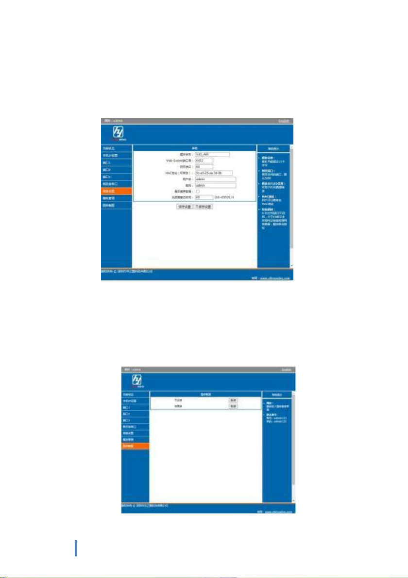
⑤ In the advanced settings, you can change the module name, user
name and password, and the default data reset time is 60 seconds.
Do not change this parameter.
⑥ Image transmission configuration, in the serial port configuration, you can
click "jump" on the air end or ground end, and after clicking, it will
automatically jump to the corresponding image transmission configuration
login interface. Video Transmission Login Username: admin123 Password:
admin123
13
www. chinowing. com

TCP serial port connection using
After connecting to the E11 network through the V21 (or a third-party
network image transmission), the serial link data transmission can be performed
through the TCP protocol or a virtual port.
Take TTL port 10 as an example, if you use the TCP protocol for
communication, open the Mission Planner ground station, select the TCP
communication mode, enter the serial port IP address of the air end 192.168. 168.19,
Port number (you need to select the external interface corresponding to the
communication of the air end), establish a connection (the baud rate does not need
to be selected), if you are using RS232, the port number is 20 and 30;
The factory default baud rate of the E11 serial port is 115200, you need
to set the flight controller or other equipment to 115200, and you can also
log in to the Web to change the baud rate of the E11 serial port;
Use of virtual serial port connection
If you want to use the COM port for communication connection, you need
to use the network virtual port tool to visualize the TCP protocol network
connection into a COM port.
14 www.chinowing.com

Install the network virtual port toolkit, click Add, and the Add Virtual
Serial Port interface will appear, select an unused port number, select
the client for the network protocol, enter the IP of the air terminal and
the corresponding port number for the target IP and port, and click OK
to see A new port ELTIMA Virtual Serial Port has been added in the
device manager, this port is the serial port virtualized by the WIFI
network
After the virtual serial port is added, select the corresponding interface to connect to
the flight controller, and select the corresponding COM port and baud rate on the
computer to communicate.
● The network virtual serial port tool can be downloaded from the official website
"www.chinowing.com" download center.
● When using the serial port on the computer side, the connection method needs to
select the TCP Client mode to access the corresponding port communication of E11.
15
www. chinowing. com

www. chinowing. com
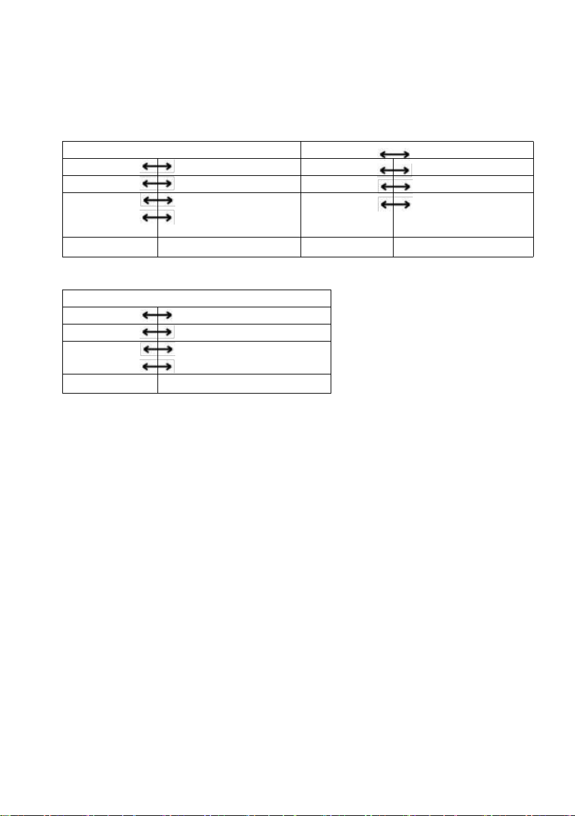
When E11 is used as a pair, connect to the LAN ports of the V21
air end and the ground end respectively, and communicate after
the V21 establishes a link.When E11 leaves the factory, the
serial port default baud rate is 115200, and the default IP
address is configured;and the default IP address is
192.168.168.18 for the ground terminal, 192.168.168.19 for the
air terminal, working mode: the air terminal is TCP Server, and
the ground terminal is TCP Client;
E11 serial port working mode independent port distinction
Type
Working
mode
Local
terminal
Interface
level
Air
terminal
TCP Server
10
TTL
20
RS232
30
RS232
Type
Working
mode
Local
terminal
Interface
level
Ground
terminal
TCP Client
10
TTL
20
RS232
30
RS232
If you need to change other configurations, you can connect to the
computer through the network cable LAN port, please refer to the "LAN port
configuration and use" chapter.
When using, connect the device to the corresponding serial
port respectively, and the level and baud rate of both ends
must be the same, otherwise normal communication cannot be
carried out. Each port of TCP Server can communicate with up
to 8 TCP Clients.
The connection method can refer to the figure below:
Table of contents
Other Chinowing Network Router manuals


Popular Network Router manuals by other brands

Patton electronics
Patton electronics IM 1/I user manual

airnet
airnet PBE-M5-400 manual

Cisco
Cisco ASR 1000 Series Common Criteria Operational User Guidance And Preparative Procedures

Atlantis Land
Atlantis Land A07-ES3526XA Specification sheet

Mercury
Mercury Broadband Router user manual

Nortel
Nortel 10292FA Installation guidelines


