Chinowing V31 User manual

V31
Video&Data&RC Link
User Manual V1.0.2

2
www.chinowing.com
Catalog
1. Disclaimer ............................................................................................................................... 3
2. Product Precautions ............................................................................................................3
3. Product Introduction and Parameters .........................................................................4
4. Item list ................................................................................................................... 5
5. Interface instruction ............................................................................................. 6
6. Product Instruction ............................................................................................... 8
6.1 S-BUS port operation........................................................................................ 8
6.2 Indicator light instruction ................................................................................ 9
6.3 Abnormal bottom noise .................................................................................. 10
6.4 Check the frequency ........................................................................................10
6.5 Serial port use ..................................................................................................11
6.6 Serial port baud rate change .......................................................................... 11
7. LAN Port Operation ............................................................................................. 12
8. USB Port Operation ............................................................................................. 14
9. Network Function ................................................................................................15
10. Module Configuration ....................................................................................... 16
11. Remote Control Fail Safe Protection Setting ................................................. 23
11.1 Write fail safe protection data ..................................................................... 23
11.2 Trigger Fail Safe Value.................................................................................. 24
11.3 Turn off Fail Safe Value.................................................................................24
11.4 Reset fail-safe data ........................................................................................ 25
12. Firmware Version View ....................................................................................25
13. Firmware Upgrading .........................................................................................26
14 Common Questions ............................................................................................ 28

3
www.chinowing.com
1. Disclaimer
Thank you for purchasing the V31 video&data&RC link. Please use it following the local
radio control regulations and read this statement carefully before using it. Once used, it
shall be deemed to endorse and accept all contents of this statement. Please strictly follow
this instruction to install and use the product. The supplier will not bear any legal liability
for any result or loss caused by improper use, installation, final assembly or modification of
the product.
2. Product Precautions
1. V31 airborne unit and ground unit need external power supply input DC7.4-30V (lithium
battery 2s-6s), please follow the specification to power the radio.
2. Be sure to install the antenna before powering up to avoid damaging the circuit.
3. Ensure that the antennas are free from obstruction and bending, and keep them as far
away from large metal objects as possible to avoid blocking communication for the above
reasons.
4. Please do not disassemble or modify the V31. If you encounter any problems that cannot
be solved during installation or use, please contact Chinowing Technology Co., Ltd.
5. Make installation with proper distance between electronic devices to minimize
electromagnetic interference.
6. Before use, make sure that all wiring is securely fastened and that all components are
working properly.
7. Please check the surrounding environment to ensure that there is no interference from
other devices in the same frequency band before use, otherwise, the data transmission of
V31 may be seriously affected
8. If you encounter any problem during the installation or use, please contact us or visit our
website at www.chinowing.com for technical support.

4
www.chinowing.com
3. Product Introduction and Parameters
V31 Digital video and data transmission module is the wireless digital data link based on
LTE wireless communication, adopting OFDM and MIMO technology. It can transmit
telemetry data and real-time video streaming and has 2*SBUS ports, able to provide control
of the drone and the payload.
There are 2 frequencies for choice, 800MHz and 1.4GHz.
High integration greatly reduces the power consumption and the dimension of the product,
which can satisfy the requirement of UAV, UGV, etc.
Item
Parameters
Description
Frequency band
800MHz
1.4GHz
806-826MHz
1427.9-1447.9MHz
RF power
2w, 5w
adjustable
Transmission
range
V31C: 5km grade(ground to ground)
V31: 20km grade(air to ground)
V31 Plus: 30km grade(air to ground)
V31 Pro: 50km grade(air to ground)
LOS condition
S-BUS port
2*S-BUS ports
NA
Serial port
1*serial port
(default: TTL; optional: RS232)
Full duplex, baud
rate adjustable
Video latency
200-300ms
Power supply
voltage
DC 7.4-30V
2S-6S battery

5
www.chinowing.com
Bandwidth
1.4-20M
1.4M/3M/5M/10M/
20M
Video
input/output
LAN
Connecting IPC
device/PC
Power supply
interface
XT30
Antenna
ZYJB antenna&fiber glass epoxy antenna
Dimension
80mm*56mm*25mm
Weight
160g(exclude antenna)
Operation
temperature
-20℃-+50℃
4. Item list
Main modules
Ground unit x 1
Airborne unit x 1
Accessories
Power
LAN-port-to-
GH signal wire 3pin* 4
Antenna*4

6
www.chinowing.com
supply cable
*2
4-pin wire *2
GH signal wire 4pin*2
Power for 2
modules
(DC7.4-30V
)
Used for
parameters
configuration
Used for TTL and
SBUS port
SMA
5. Interface instruction
Front view
①Data receiving indicator: light will flicker in the condition of data receiving.
②Data transmitting indicator: light will flicker in the condition of data transmitting.

7
www.chinowing.com
③Signal strength indicator: green light indicates signal strength; red light indicates
abnormal antenna bottom noise.
④SET button: used for firmware upgrading, serial port baud rate setting, out-of-control
protection settings
⑤SMA antenna connector: main antenna, able to transmit and receive signal.
⑥SMA antenna connector: secondary antenna, able to receive signal.
Side view
①TTL port: full duplex serial port(RS232 optional)
②S-BUS1port: SBUS input(ground unit);SBUS output(airborne unit)
③S-BUS2 port: SBUS input(ground unit);SBUS output(airborne unit)
④Power supply port: 7.4-30V
⑤TTL signal indicator: light will flicker when there is data input
⑥SBUS1 indicator:
Ground unit: SBUS1 indicator will flicker when there is data input of SBUS1.
Airborne unit: SBUS1 indicator will flicker when there is data output of SBUS1.
⑦SBUS2 indicator:
Ground unit: SBUS2 indicator will flicker when there is data input of SBUS2.
Airborne unit: SBUS2 indicator will flicker when there is data output of SBUS2.

8
www.chinowing.com
LAN port: for video input or output
USB port: debugging interface. After the driver is installed, a virtual NIC can be used
6. Product Instruction
Power on the airborne unit and ground unit. After the successful connection of the two
modules(signal indicator is constant, this process takes about the 30s), the device can work
normally, and all parameters have been configured well. If you want to modify the baud rate
of the serial port and the IP address of the network port, please refer to the corresponding
steps.
Note! The products are factory configured and ready for use. Default configuration
parameters.
User name: admin123
Password: admin123
LAN port IP: 192.168.168.12 (airborne unit); 192.168.168. 11(ground unit)
Secret key: 88
Wireless parameters: frequency: 1.4G/800MHz; frequency hopping mode: enabled;
bandwidth: 20M
Serial port parameters: baud rate: 115200; 8 data bits; 1 stop bit; no parity
6.1 S-BUS port operation
1. Connect the SBUS port of V31 ground unit with the SBUS signal source of RC receiver. The
SBUS indicator will flash quickly when there is data input.
2. Connect the SBUS port of V31 airborne unit to the device you need to control.

9
www.chinowing.com
3. V31 can control aircraft, gimbal and other devices as long as the link is connected.
6.2 Indicator light instruction
Indicator
Status
Define
TXD
Flashing
There is data transmitting
OFF
There is no data transmitting
RXD
Flashing
There is data receiving
OFF
There is no data receiving
TTL/RS232
Flashing
Serial port data is in the
communication
OFF
No serial port data
SBUS 1
Flashing
SBUS1: there is signal transmission
OFF
SBUS1: there is no signal
transmission
SBUS 2
Flashing
SBUS2: there is signal transmission
OFF
SBUS2: there is no signal
transmission
LAN
Flashing
The LAN port has been connected.
Signal strength
indicator RS1, RS2,
RS3
RS1&RS2&RS3 ON
Strong signal
RS1&RS2 ON, RS3 OFF
Moderate signal
RS1 ON,RS2&RS3 OFF
Weak signal
RS1, RS2, RS3 OFF or
Show the running horse lights
No connection
Bottom noise fault
(S1, S2, S3, red)
S1 flash(red)
Failure connection of the main
antenna
S2 flash(red)
Failure connection of the secondary
antenna

10
www.chinowing.com
6.3 Abnormal bottom noise
When S1 red light is flashing, the main antenna has poor bottom noise; when S2 red light is
flashing, the secondary antenna has poor bottom noise.
Please check whether there is any abnormality of the corresponding antenna, feeder line,
connection and installation position when there is bottom noise fault phenomenon,
otherwise it will affect the transmission distance.
The bottom noise prompt function is suitable for the pre-flight check, like indoor installation
and debugging. It works in the range of 200 meters between Tx and Rx after V31 link
successful connection. This function will be closed automatically after the range is more than
200 meters.
For the bottom noise test, pls try to avoid going through walls, etc, in case of inaccurate
results. Pls, do it in the LOS condition.
6.4 Check the frequency
V31 has 2 frequencies for choice, 800MHz, 1.4GHz.
For frequency checking, pls press the SET button <3 seconds when power on, S3 indicator
light Red indicates 800MHz; S2, S3 indicator lights Red indicates 1.4GHz.
Short press SET key<3S,
S3 ON(red)
Indicating 800MHz frequency
Short press SET key<3S,
S2, S3 ON(red)
Indicating 1.4GHz frequency
S1&S2&S3
Sharp-flash
Outputting Failsafe protection data

11
www.chinowing.com
6.5 Serial port use
The default baud rate of the serial port is 115200. Pls, follow the below methods to connect
the flight control and ground station software.
1. Connect flight control to the airborne unit. Pls kindly be noted the line sequence as well
as the baud rate of the flight control port must be the same as the baud rate of the serial
port.
2. Connect the ground station software to the ground unit. Pls kindly be noted that the line
sequence as well as the baud rate of the port selected by the ground station software must
be the same as the baud rate of the serial port.
6.6 Serial port baud rate change
Press and hold the SET key after the module is powered on(about 3 seconds). When RX and
TX light up, release the key, which indicates that the module has entered the mode of
changing the baud rate. After entering the mode, press the SET key briefly (<1 second) to
switch the baud rate. The corresponding LED ON represents the corresponding baud rate
value.
Details are as follows:
Indicator status
Baud rate
Rx continuously ON
9600bps
Tx continuously ON
19200bps
S1 continuously ON
38400bps
S2 continuously ON
57600bps
S3 continuously ON
115200bps
After finishing the setting, long press the SET key (about 2 seconds). When TX and RX light
up at the same time, pls release the key. After release, the indicator will return to the normal

12
www.chinowing.com
working state. After the modification is completed, the baud rate needs to be re-powered to
take effect.
Note: when changing the baud rate, it needs to be the same for the airborne unit, ground
unit, flight control, or other devices for normal communication.
7. LAN Port Operation
Pull-streaming video can be acquired using the LAN port
1. Default IP address:
airborne unit: 192.168.168.12; ground unit: 192.168.168.11
2. Connect the LAN port of the airborne unit to IPC devices.
3. Connect your computer to the LAN port of the ground unit, and make sure that the IP
address of your computer's local connection is on the same network segment as the
camera.
①Open Computer network sharing center
②Open the Change Adapter option
③Select the local connection to the ground unit and right-click on it to view the properties.

13
www.chinowing.com
④Select Internet IPV4 protocol, set the fixed IP, and set the IP to the same network segment
as the camera, e.g.: the camera IP is 192.168.167.10, set the local IP to 192.168.167.xxx
(0~255) except 10. When the modification is finished, click "OK".
⑤Capture and play the video data using streaming software such as VLC Media Player.
Pls, ignore the IP address of V31 when setting the IP address in getting video by pull
stream. Just change the local IP address of the computer to the same network segment
as the LAN camera.
For more tutorials, please refer to our website www.chinowing.com.
14
www.chinowing.com
8. USB Port Operation
The USB port incorporates a virtual network card function that can be used for video and
data output. Before using the USB port, the user must install the appropriate driver. The
steps are as follows:
1. Install V31 CODEDRIVER driver
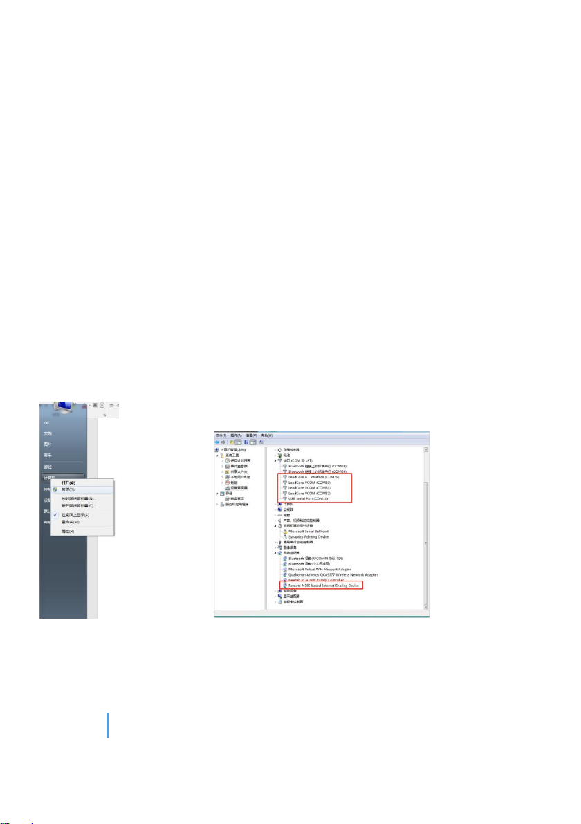
2. The installation process may be intercepted by the security guard, please close the
security guard or trust this operation. After the successful installation, connect the USB port
to the PC, and open Computer->Management, you can see 5 ports will appear in the port
management interface(not open for use yet). < Remote NDIS-based Internet Sharing Device>
will appear in the interface of the network adapter, indicating that the USB port connection
is successful.
Note: Please do not use the USB port until the device is successfully connected. Otherwise,
the signal strength indicator may appear abnormal.
3. Open the Network Sharing Center and set the local connection to get static IP.
15
www.chinowing.com
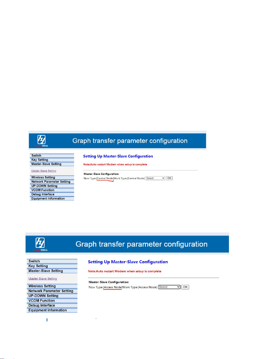
9. Network Function
V31 Radio supports network communications and is a point-to-multipoint product that
supports up to 16 slave devices. The ground unit can be set as the master and the airborne
unit as the slave. The ground unit can be connected to max 16 airborne units, and through
the TTL interface, the ground unit can transmit data to 16 airborne units. The data
transmitting and receiving can be realized through LAN port between airborne units.
Operation steps are as follow:
1. Set the ground unit as the master device.
2. Set the airborne unit as the slave device

16
www.chinowing.com
3. The IP address of the ground unit and other airborne units must be in the same network
segment, and cannot have the same IP address to avoid IP conflicts and inaccessibility. For
example, the ground unit IP is 192.168.168.11, other airborne unit IP is 192.168.168.12,
192.168.168.13...
4. Data is input from the TTL interface of the ground unit and data can be received by the
TTL interface of each airborne unit.
5. The airborne unit accesses other IP-connected devices of the other airborne unit(e.g., LAN
camera, etc.) via a network interface IP.
a. The IP address of the camera connected to the airborne unit is 192.168.167.20;
b. Other airborne units connect to PC via Ethernet port, set local connection to static IP,
IP is on same network segment as camera, eg.192.168.167.30;
c. Use pull stream software to play the video.
10. Module Configuration
Take <airborne unit LAN port IP: 192.168.168.12; Ground unit LAN port IP:
192.168.168.11> for example:
①Power on the modules. Wait for the module to start for about 30s, connect the PC to
the LAN port of the ground unit through the network cable to access the airborne unit
directly from the ground unit, or connect the airborne unit to the computer separately.

17
www.chinowing.com
②Set the local IP to static IP in the computer network sharing center, IP should be the
in the same network segment with airborne unit IP, for example.192.168.168.15.
③Open a browser and enter IP in the address bar: 192.168.168.11
④Pop up the login interface and click on the administrator login, user name:
admin123, password: admin123.
If the login doesn't work or writes "This browser does not support ActiveObject,
download another browser (e.g. Sogou or Microsoft Edge) or update your browser
version and try again.

18
www.chinowing.com
⑤After successful login, the module configuration interface will appear.
<Key Settings Management> allows the user to set the secret key, which
must be the same between the airborne unit and the ground unit for
communication.
It is recommended that you do not modify the <Master-Slave Settings> of
the <Wireless Settings> to avoid the possibility of poor communication
quality due to improper settings.
<Wireless Setting> can modify the frequency band, bandwidth, power and
frequency hopping. When modifying the frequency band and bandwidth,

19
www.chinowing.com
please make sure the frequency band and bandwidth of the airborne unit
and ground unit should be the same, the antenna model used is consistent
with the frequency band. In different sub-model, the max power is different.
<IP Address Change Management> can modify IP addresses. It is not
recommended to change the IP address randomly. If the user wants to
change it, please make sure that the ground unit and the airborne terminal
are on the same network segment.
<UP- Down Settings Management> allows the user to change the ratio of
uplink rate to downlink rate. If there is not any question, it is not
recommended to modify it. If it is needed, the airborne unit setting is valid,

20
www.chinowing.com
<1D4U> means the ratio of downlink and uplink is 1:4.(master node to slave
node is DOWN, slave node to slave node is UP).
To ensure smooth video play, there are different parameters settings in different application
scenarios:
Scenario 1:
Table of contents
Other Chinowing Network Router manuals


Popular Network Router manuals by other brands


Edimax
Edimax BR-6428n user manual

Linksys
Linksys WET54GS5 - Wireless-G EN Bridge Quick installation

TP-Link
TP-Link Archer BE805 user guide

Freescale Semiconductor
Freescale Semiconductor T1023WLAN Getting started guide

Linksys
Linksys RV0041 - 10/100/1000 VPN Router Quick installation

Cisco
Cisco 850 Series quick start guide


